İZMİR KATİP ÇELEBİ UNIVERSITY GRADUATE SCHOOL OF NATURAL AND APPLIED SCIENCES
M. Sc. THESIS
JULY 2016
IMPROVEMENT OF ENGINEERING PROPERTIES AND LIQUEFACTION REDUCTION OF SANDY SOILS USING ELECTRIC ARC FURNACE SLAG
AND ROOF TILE POWDER
Thesis Advisor: Assist. Prof. Dr. Adem EREN Drinela AGOLLI
Civil Engineering Programme
JULY 2016
İZMİR KATİP ÇELEBİ UNIVERSITY GRADUATE SCHOOL OF NATURAL AND APPLIED SCIENCE
IMPROVEMENT OF ENGINEERING PROPERTIES AND LIQUEFACTION REDUCTION OF SANDY SOILS USING ELECTRIC ARC FURNACE SLAG
AND ROOF TILE POWDER
M. Sc. THESIS Drinela AGOLLI
Y130104025
Civil Engineering Programme
TEMMUZ 2016
İZMİR KATİP ÇELEBİ ÜNİVERSİTESİ FEN BİLİMLERİ ENSTİTÜSÜ
KUMLU ZEMİNLERİN MÜHENDİSLİK ÖZELLİKLERİ VE SIVILAŞMA DİRENÇLERİNİN ELEKTRİK ARK FIRIN CÜRUFU VE KİREMİT TOZU
KULLANILARAK İYİLEŞTİRİLMESİ
YÜKSEK LİSANS TEZİ Drinela AGOLLI
Y130104025
İnşaat Mühendisliği Anabilim Dalı
Tez Danışmanı: Yard. Doç. Dr. Adem EREN
v
Thesis Advisor : Assist. Prof. Dr. Adem EREN ... Izmir Katip Çelebi University
Jury Members : Assoc. Prof. Dr. Erdal AKYOL ... Pamukale University
Assist. Prof. Dr. Nesrin HORZUM POLAT ... Izmir Katip Çelebi University
Drinela Agolli, a M.Sc student of Izmir Katip Celebi University / Graduate School of Natural and Applied Science , student ID Y130104025, successfully defended the thesis entitled “Improvement of Engineering Properties and Liquefaction Reduction of Sandy Soils Using Electric Arc Furnace Slag and Roof Tile Powder”which she prepared after fulfilling the requirements specified in the associated legislations by the jury whose signatures are below.
Date of Submission : 20thJune 2016 Date of Defense : 13th July 2016
vii
ix FOREWORD
I would like to express my sincere gratitude to Assist. Prof. Dr. Adem EREN for his guidance and encouragement throughout the work for this thesis, as well as for his support throughout the entire studies at IKCU. It was great learning experience working with him and his assistance was very crucial.
I wish to express my sincere thanks to Assist. Prof. Dr. Gulmustafa SEN, Assoc. Prof. Dr. Salih YILMAZ who have been a constant source of inspiration for me throughout this thesis work.
I would like to thank also Assoc. Prof. Dr. Erdal AKYOL, Assist. Prof. Dr. Nesrin Horzum POLAT and Assist. Prof. Dr. Zeynep TASCI for their valuable recomendation during preparation of this thesis.
The cheerful support of my friends and colleagues is sincerely appreciated. Special words of appreciation go to my friend Orjeta Salihaj for her great support, inspiration and begin always whenever I needed throughout all my studies. I would like to thank Ornela Lalaj for her help and great support.
Above all, I thank my parents and my brothers, whose love and affectionate blessing have been a constant source of inspiration in making this manuscript a reality.
xi TABLE OF CONTENTS Page FOREWORD ... ix TABLE OF CONTENTS ... xi LIST OF TABLES ... xv
LIST OF FIGURES ... xvii
SUMMARY ... xix
ÖZET ... xx
1. INTRODUCTION ... 1
1.1 Purpose of Thesis ... 2
1.2 Organization of the Thesis ... 2
2. REVIEW OF GROUND IMPROVEMENT METHODS AND LIQUEFACTION ... 3
2.1 Literature Review of Ground Improvement Techniques ... 3
2.3 Literature review for liquefaction ... 12
2.4 Photogrammetric approach ... 14
3. CHARACTERISTICS OF MATERIALS USED ... 17
3.1 Slag ... 17
3.2 Blast furnace slag ... 19
3.2.1 Air-cooled blast furnace slag ... 20
3.2.2 Expanded or foamed blast furnace slag ... 20
3.2.3 Pelletized blast furnace slag ... 20
3.3 Electric arc furnace slag ... 21
3.4 Sand ... 22
3.5 Roof tile powder ... 23
3.6 Diatomite ... 23
3.7 Sulfuric acid ... 24
3.8 Environmental impact ... 25
4. SOIL PREPARATION & EXPERIMENTS ... 27
4.1 Sieve analysis ... 27
4.2 Specific gravity test ... 28
4.3 Wet sieve analysis ... 28
4.4 Direct shear test ... 29
4.5 Unconfined compressive strength test ... 30
4.6 1-D shaking table test ... 30
4.7 Methodology steps ... 31
5. ANALYSIS OF THE TEST RESULTS ... 33
5.1 Test results of mixture EAF slag+ Water ... 33
5.2 Test results of EAF slag+ sand+ lime+ H2SO4 mixture ... 36
5.3 Test results of eaf slag+ sand+ lime+ acetic acid mixture ... 37
5.4 Test results of EAF slag+ sand+ H2SO4+ Roof tile powder mixture ... 38
5.5 Test results of EAF slag+ sand+ HCl+ TEOS mixture ... 39
5.6 Test results of EAF slag+ sand+ lime+ H2SO4+(NaPO3)6 mixture ... 40
5.7 Test results of EAF slag+ sand+H2SO4+Diatomite mixture ... 41
5.9 1-D shaking Table tests ... 43
5.10 Volume expansion effect ... 47
5.11 Cost analysis ... 48
6. CONCLUSIONS AND RECOMMENDATIONS ... 49
xii
APPENDIX ... 55 CURRICULUM VITAE ... 61
xiii ABBREVIATIONS
EAF : Electric Arc Furnace Slag H2SO4 : Sulphuric Acid
TEOS : Tetraethyl Orthosilicate HCl : Hydrochloric Acid PC : Portland Cement BFS : Blast Furnace Slag
GGBFS : Ground Granulated Blast Furnace Slag XRF : X-Ray Fluorescence
UCS : Unified compressive strength CH3COOH : Accetic acid
xv LIST OF TABLES
Table 2.1: Cement ratio ranges for stabilization (Das, 2011) ... 7
Table 3.1: The oxide composition values in literature (Autelitano and Giuliani, 2015) ... 21
Table 3.2 : EAF oxide composition ... 22
Table 3.3 : Physical properties of sand ... 22
Table 3.4 : Literature values of chemical composition (URL 1) ... 24
Table 3.5 : Physical properties of sulfuric acid (URL 2) ... 24
Table 4.1 : Mixing proprotions of components by weight ... 32
Table 5.1 : Mixing proportions of additives (%) ... 35
Table 5.2 : Mixing proportions ratio of components (%) ... 41
Table 5.3 : Compressive strength 7 days curing (MPa) ... 42
Table 5.4 : Displacement results ... 45
Table 5.5: Settlement calculation ... 47
xvii LIST OF FIGURES
Page
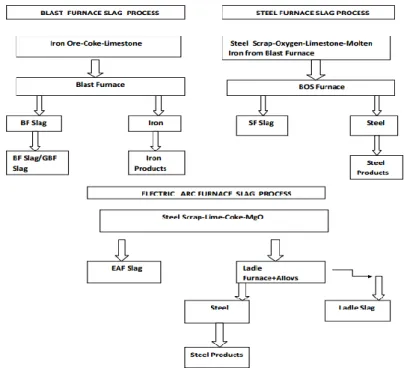
Figure 3.1 : Flow chart showing the processes of various slag (ASA, 2002) ... 18
Figure 3.2 : General schematic of blast furnace operation and blast furnace slag production (TFHR, 2004)... 19
Figure 3.3 : a) Blast furnace slag b) Air-cooled blast furnace slag c) Pelletized blast furnace slag ... 21
Figure 3.4 : Limits in the gradation curve seperating liquefiable soils (modified from Tsuchida, 1970) ... 23
Figure 4.1: Stack of sieves ... 27
Figure 4.2 : Dessicator and pycnometer... 28
Figure 4.3 : Washing of sandy soil thorugh sieve with diameter 74 µm ... 28
Figure 4.4 : Mohr-Coulomb failure envelope ... 29
Figure 4.5 : Direct shear test ... 29
Figure 4.6 : Unconfined compressive strength test machine ... 30
Figure 4.7 : 1-D shaking table ... 31
Figure 5.1 : Maximum carrying force (N) of EAF slag + water mixture ... 34
Figure 5.3 : Unmolded specimens or spread during unmolding ... 34
Figure 5.4 : Failure mode of specimens ... 35
Figure 5.5 : Specimen with sulphuric acid a) before and b)after test. ... 36
Figure 5.6 : Specimen with lime a) before and b) after test ... 36
Figure 5.7 : Maximum compressive strength of mixture with H2SO4 (MPa) ... 37
Figure 5.8 : Failure mode of specimens ... 37
Figure 5.9 : Specimes view a) before and b) after failure ... 38
Figure 5.10 : Maximum compressive strength of mixture with roof tile powder (MPa) ... 39
Figure 5.11 : Failure mode of specimens ... 39
Figure 5.12 : Relationship between force & displacement of mixtue with EAF slag+ sand+ HCl+ TEOS ... 40
Figure 5.13 : Failure mode of specimen ... 40
Figure 5.14 : Maximum compressive strength of mixture with (NaPO3)6 salt (MPa) ... 41
Figure 5.15 : Failure mode of specimens ... 41
Figure 5.16 : Maximum compressive strength of mixture with diatomite (MPa) .... 42
Figure 5.17 : Failure mode of specimens ... 42
Figure 5.18 : Comparison of maximum compressive strength between two different mixtures ... 43
Figure 5.19 : Failure mode of specimen ... 43
Figure 5.20 : Experiment Setup a) water + sand mixture b) water + steel slag+ sand mixtures c) water + steel slag+ sand + H2SO4 ... 44
Figure 5.21 : Markers to be surveyed. ... 44
Figure 5.22 : Place where markers are placed ... 45
Figure 5.23 : Behavior of structure before and after shaking. a) unmixed soil sample b) mixed soil sample EAF slag c) mixed with EAF slag + H2SO4 ... 46
Figure 5.24 : Chart for estimation of volumetric strain in saturated sands from cyclic stress ratio and standard penetration resistance (After Tokimatsu and Seed, 1987) ... 46
xviii
Figure A.1 : Force- displacement curves of mixture 3 ... 56
Figure A.2 : Force- displacement curves of mixture 2 ... 57
Figure A.3 : Force- displacement curves of mixture 5 ... 58
xix
IMPROVEMENT OF ENGINEERING PROPERTIES AND LIQUEFACTION REDUCTION OF SANDY SOILS USING ELECTRIC ARC FURNACE SLAG
AND ROOF TILE POWDER
SUMMARY
The scarcity of suitable land for construction of engineering facilities and shortage of natural earth aggregates has highlighted the need for finding innovative way of construction. Nowadays problematic soils such as: soft clay, organic soils and liquefiable soils can be improved to the required civil engineering requirements by application of soil stabilization. Soil stabilization is a method intended to increase or preserve the stability of soil mass and chemical alteration of soil to improve engineering properties.
Generally, ground treatment techniques used are: densification, reinforcement, drainage and deep soil mixing. Using soil treatement, unbound materials can stabilized with cementitious materials (lime, cement, fly ash, waste materials). Replacement of stabilizing agents with waste materials is becoming a need due to lack of natural resources and environmental concerns. Slag a by-product of metallurgical industry is being used to improve engineering properties of low bearing capacity soils.
In this study, mechanical properties of non-cohesive soils are improved using waste materials. Waste material used is: electric arc furnace slag (EAF slag). Natural materials diatomite and roof tile powder are mixed too. In order to activate slag, some chemical additives were added. Firstly, cylindrical samples with different proportions were prepared. They were tested for period of 7, 21 and 28 days under unconfined compressive strength (UCS) test. The optimum mixture was tested also under 1-D shaking table subject to different earthquake records. Photogrammetric approach was used to observe behaviour of soil under dynamic load and settlement.
It was seen that combination giving the highest compressive strength was mixture containing EAF slag, sand, lime and sulphuric acid (H2SO4). The highest compressive
strength obtain was 7.736 MPa. Bonding capacity between EAF slag and sand is increased by addition of sulphuric acid. Liquefaction effect and settlement was reduced compare to control sample. Photogrammetric approach seems to be a valuable way to calculate settlement of a structure. Soil stabilization with EAF slag waste material with some deeper studies can be a useful method to treat non-cohesive soils.
xx
KUMLU ZEMİNLERİN MÜHENDİSLİK ÖZELLİKLERİ VE SIVILAŞMA DİRENÇLERİNİN ELEKTRİK ARK FIRIN CÜRUFU VE KİREMİT TOZU
KULLANILARAK İYİLEŞTİRİLMESİ ÖZET
Mühendislik yapıları için uygun arazinin az bulunması ve doğal yeryüzü agregasının kıtlığı, yenilikçi yapım şekli bulma ihtiyacını doğurmuştur. Günümüzde yumuşak kil, organik ve sıvılaşabilir zeminler gibi problemli olan zeminlerin stabilizasyonu yapılarak inşaat mühendisliği için uygun projeler gerçekleştirilebilir. Zemin stabilizasyonu, zeminlerin kütlesel ve kimyasal değişikliğe uğramasını önlemek veya stabilitesini korumak için mühendislik özelliklerini iyileştiren bir tekniktir.
Genellikle kullanılan zemin iyileştirme teknikleri, yoğunlaştırma, güçlendirme, drenaj ve derin karıştırmadır. Bağlayıcısı olmayan malzemeler de zemin iyileştirmesi için kullanılan çimentolu malzemeler (kireç, çimento, uçucu kül, atık maddeler) ile zemin iyileştirmesi yapılabilir. Çevresel kaygılar ve doğal kaynakların eksikliği, dengeleyici malzemeler ile atık malzemelerin yer değiştirmesi ihtiyacını doğurmaktadır. Metalurji sektörünün bir yan ürünü olan cüruf, düşük taşıma kapasitesine sahip zeminlerin, mühendislik özelliklerinin iyileştirilmesi için kullanılmaktadır.
Bu çalışmada, kohezyonsuz zeminlerin mekanik özellikleri, atık malzemeler kullanılarak iyileştirilmiştir. Kullanılan atık malzeme, elektrik ark fırın cürufudur (EAFC). Doğal malzeme olan diatomit ve kiremit tozu da karıştırılarak mühendislik özelliklerinin değişimi incelenmiştir. Cürufu aktif hale getirmek için bazı kimyasal katkı maddeleri de ilave edilmiştir. Hazırlanan silindirik numuneler üzerinde 7, 21 ve 28 günlük periyotlarda bekletildikten sonra serbest basınç dayanım (SBD) testi yapılmıştır. Optimum karışımın sıvılaşma direncinin değerlendirilebilmesi için, laboratuvar ortamında farklı deprem kayıtları altında bir boyutlu (1-D) sarsma tablası deneyleri yapılmıştır. Dinamik yükleme altında zemin davranışı ve oturmaları değerlendirmek için fotogrametrik yaklaşım kullanılmıştır.
İçerisinde EAFC, kum, kireç ve sülfürik asit (H2SO4) olan karışımın dayanımı 7,736
MPa ile en yüksek basınç dayanımına sahip olduğu görülmüştür. EAFC ve kum arasındaki bağ kapasitesi, sülfürik asit eklenmesi ile arttırılmıştır. 1-D sarsma tablası deneyleri incelendiğinde elde edilen karışımın sıvılaşma direncinin arttığı ve oturmaların da etkisi azaltılmıştır. Yapıların oturmasını hesaplamak için fotogrametrik yaklaşımın kullanılabilirliği de böylece ortaya konmuştur. Yapılacak daha ayrıntılı çalışmalarla, EAFC atık malzemesinin zemin stabilizasyonun da kullanılması kohezyonsuz zeminlerin iyileştirilmesi için kullanışlı bir yöntem olduğu değerlendirilmektedir.
1 1. INTRODUCTION
Ground treatment is quite an old technique and it has been stated that soil improvement is apparently the oldest of all common improvement methods in civil engineering discipline. Soil stabilization binds stabilizing agents in weak soils to improve geotechnical properties such as strength, permeability, compressibility and durability. Most of soil stabilization is applied into soft soils, but they are not the only problematic soils. Due to natural disasters, such as earthquakes, poor sandy soils loses their strength and carrying capacity. In addition, liquefaction starts to occur. Mogami and Kubo (1953) defined liquefaction as loss of shear strength due to seismically induced cyclic loading. Since soil after liquefaction occurrence is not able to safely transmit the loads that are imposed upon, it needs to be treated.
Many methods have been presented to increase liquefaction resistance. Generally, the main methods used to mitigate liquefaction are categorized as densification, reinforcement, drainage and deep soil mixing. These traditional methods generally have high energy-consumption needs and high costs, and some of them are unsuitable for use over large areas (Khodadadi and Bilsel, 2012). In addition, lack of natural resources, environmental concern and the need for reduction of construction cost has led to the use of industrial wastes as stabilizing agents. Slag can be used as a stabilizing agent. Slag is a waste material obtained from iron core and available material in many countries. It can be reusable and has low cost of usage. It has similar characteristics to natural crushed stone or sand. Slag has the characteristics of solidification and brittleness after curing. Generally, chemical composition of the slag consists of oxides of calcium, silica, alumina etc, and is an important parameter effecting the reaction with other soil chemical elements found in soil. It doesn’t contain cementitious compound itself, but it has latent hydraulic properties which can be activated by addition of lime or alkaline material (Sherwood, 1993; Åhnberg et al., 2003).
For a notable stabilization, laboratory tests followed by field tests may be needed to estimate the engineering properties of treated soil. UCS test is used to identify maximum carrying capacity of treated soil and for liquefaction assessment are used
2
both laboratory and field tests. SPT and CPT tests are field test used to assess liquefaction. The laboratory methods include direct shear test, triaxial shear test, torsion shear test, centrifuge tests, ring shear test and shaking table test.
UCS tests and 1-D shaking table tests were carried out to investigate the behavior of sandy soils. Increase in carrying capacity and reduction of liquefaction was possible by involving waste materials in soil stabilization.
1.1 Purpose of Thesis
This study plans to use industrial waste material as soil stabilizer to improve the behavior of liquefiable sandy soils.
The aims are as listed below:
1. Investigation of the behavior of liquefiable sandy soils with particle size 0.250-0.425 mm improved with waste material such as: electric arc furnace slag, roof tile powder diatomite and chemical additives.
2. Conduction of UCS test and optimization of mixtures to be selected.
3. Testing of optimum mixture obtained under 1-D shaking table subject to well-known earthquake records (El Centro, 1940; Niigata, 1964; Loma Prieta, 1989; Northridge, 1994; Kobe, 1995; Kocaeli, 1999).
1.2 Organization of the Thesis
The thesis consists of six chapters. The first chapter presents an introduction of the study that is related to the entire work. Chapter 2 presents a literature review of existing ground improvements methods, liquefaction and adverse effects of it. The characteristics of the materials used for improvement of engineering properties of soil are presented in Chapter 3. Chapter 4 displays sample preparations, types of mixtures and the conduction of the required laboratory tests. Evaluations of test results are discussed in Chapter 5. In Chapter 6, summary and findings of this study are presented. The last chapter is followed by a list of references
3
2. REVIEW OF GROUND IMPROVEMENT METHODS AND LIQUEFACTION
2.1 Literature Review of Ground Improvement Techniques
Data and instructions how soil stabilization is implemented havebeen well documented. Many journal articles and textbooks are available. The first part of this review discusses literature cases about ground improvement techniques used against liquefaction. The second part briefly discuses liquefaction effect to soil.
Basic concepts of soil improvement, as introduced in ASCE (1978) report on soil improvement such as densification, cementation, reinforcement, drainage, drying and heating were developed hundreds or thousands of years ago and still continues to be unchanged. There have been a lack of space devoted to the soil improvement subject in early soil mechanics books and in journals. The first papers related to ground treatments were introduced in the First Geotechnique Conference held on 29 May 1975. Initially, ground treatment methods of that time were surrounded by mistery. All methods were at primitive state. Generally, ground improvement methods consisted of required ground behavior for particular use of the ground, identifying any deficiency in ground behavior (Burland et al., 1976).
Compaction stands for densification of soil by dynamic methods, which based on the method of conveying the energy to the soil, can be divided into two main groups, impact compaction and vibratory compaction. Massarsch (1991; 1999), Mitchell (1982) and Schlosser (1999 have extensively described the methods and their practical applications.
Dynamic compaction is a technique of subgrade strengthening consisting of non-cohesive sand soils. This method is used to strengthen weak soils up to the depth of 14 m (in practice up to 10 m high). Vibro compaction is likely the oldest deep compaction method existing. It was founded by Johann Keller Company in 1936, following the finding of the depth vibrator. Schneider (1938), Greenwood (1976) and Kirsch (1993) reported a detailed description of the method from its beginnings up to the pre-war
4
period. This technique is the most suitable for the stabilization of soils with limited amounts of fines. Mitchell (1981) reported that the best desirable soils for vibro compaction are when the soil’s fines content is 18%. Woodward (2005) proposed that when fines content is less than 10% best results can be obtained.
Falkner et al., (2010) reported a theoretical investigations of the rapid impact compaction (RIC), which involves numerical computer simulations of the impulse type compaction effect, the energy transfer into the soil, and the wave propagation. Experimental tests in different soil conditions gave a verification of the theoretical analyses. They slso gave the basis for an optimized and economical application of the compaction method in practice. Case studies of different construction projects showed a successful application of the RIC for middle-deep improvement and compaction of the ground.
Simpsons (2008) observed a case study on the use of the RIC at a reclaimed site (1.21 km2) in California, USA. Pre and post treatment Cone penetration test (CPT) results were given. The comparison of the state before and after liquefaction potential was also done. The results of vibration monitoring performed during conduct of the RIC method were examined. It was summarized that the RIC is a suitable and economical ground improvement method and liquefaction mitigation method as well.
Tarawneh and Matraji (2014) evaluated the usefulness of RIC technique in the Arabian Gulf Region. The RIC technique was used to improve an area of 29,000 m2 on a project
site near Dubai, UAE, where the groundwater level is shallow. Cone Penetration Tests (CPT) and settlement calculations were performed before and after soil improvement. Test results demonstrated improvement in the soil bearing capacity and decrease in expected settlements.
Sand compaction pile (SCP) is a soil stabilization technique that is used to improve stability, control liquefaction and reduce settlement of various structures. The behavior of SCP is similar to that of stone columns. These piles can significantly accelerate the pore water pressure dissipation process and the time for consolidation when built in soft soils. It combines fundamental principles of ground improvement, such as densification and drainage. SP were first constructed in Japon in 1930(Ichimoto, 1981).SCP technique is most used in Japan as countermeasure against liquefaction (Harada,2004).
5
Okamura et al., (2002) demonstrated that during the improvement of a site by SCP, where the compaction piles are put into the soil by pressurized air supplied from the top of the casing, some of the air percolated into the sand and some spouted from the ground surface. Based on this investigation, Okamura et al., (2002) observed another site treated 26 years ago by SCP and concluded that air bubbles survived for 26 years. Having this supportive evidence, the authors also studied whether or not air/gas will remain entrapped under groundwater flow at low and high gradients. Large scale constant head flow test setups were prepared.
Stone columns are a ground improvement technique that used to increase the load-bearing capacity of shallow foundation on soft clay layers. Adalier et al.,(2003) found that when trying to stabilize nonplasticsilty soils, only the third benefit can be expected primarily to mitigate liquefaction. This method has been applied since late 1950s. Gnieal and Bouazza (2008), Shenthan et al., (2004), Mitra and Chathpadhyay (1999) have presented that during an earthquake, stone columns can behave as a gravel drain column to discharge pore water pressure and the liquefaction potential of a ground can be reduced. Gniel and Bouazza, (2008) suggested that conventional stone columns in soft soil deposits was found to be beneficial for foundations in many respects. Reinforced short pile method can be applied to improve the stability of the structure and avoid the liquefaction damages to the structures. Cernica (1995) found that the length and diameter of the reinforced short pile are important in application.
Arman et al., (2009) in their study proposed the application of modified dry bottom feed stone column as dominant ground improvement method in the region of Adapazari city in Turkey. A numerical analysis was performed to check performance with respect to displacement. Results showed that significant improvements were achieved in terms of displacement.
Jet grouting is a soil stabilization technique, in which cement slurry is injected into the soil at high velocity to create a soil-concrete matrix. The process of jet grouting was first developed in 1960s. Most of the research work was implemented in Japan, (Ohata and Shaibzaki, 1982). Later on,it was spread in Europe in 1970s.
Jet grouting technique can be used to treat a whole range of soils, from silty sands to cohesive deposits, by using cement grouts. It can be applied to soils with a wide range of granulometries and permeability.
6
Yasuda (1993) reported that, in Japan during the period 1985-1990, deep densification by different methods was implemented at 175 sites, partial improvement or hardening was used at 16 sites, drainage to decrease saturation was carried out on 22 sites, and drains to prevent large buildup of excess pore pressures were executed at 101 sites. Deep mixing stabilization is one of the methods used to mitigate liquefaction. It was first developed in 1954 in USA. Later it was spreaded in Japan (1960), Sweden and it is nowadays worldwide known. At the beginning, this method used lime as binder material for treatment of soft-clay soils. Later in 1975, cement was used as fluid cement grouting for treatment of soft marine soils (Bruce, 2000).
Deep mixing as a soil stabilization technique which enhances the engineering characteristics of soil, consisting in increased strength, low compressibility, permeability and erodability, liquefaction mitigation, reduction of water content and increased durability in dynamic or cyclic actions (Nicholson & Peter, 2014).
In deep mixing method, different admixtures are used as binder, such as lime, cement, fly ash, and waste materials.
Lime stabilization is a ground stabilization method in which soil is mixed with lime used to modify the soil, improve the strength and durability. Lime is the first binder used to enhance the geotechnical characteristics of the ground. The quantity of lime used to improve most soils varies from 5 to 10%.
Sherwood, (1993) reported that soil stabilization using lime provided an increase in strength by cation exchange capacity rather than by cementing effect of pozzolanic reaction.
The types of lime used for mixing are high calcium lime, calcitic quicklime andmonohydrated dolomitic lime. Rogers et al., (1996) presented that quicklime is the most commonly used lime for soil stabilization.
Tran (2014) noted that lime soil treatment can be used in various applications such as roads, highways, embankments, dams, airfields, etc. to enhance the shear strength, reduce the deformations and decrease water content.
Cement is being extensively used as a stabilizing material for soil, generally for construction of highways and earth dams. It is used to stabilize sandy and clayey soils. When liquid limit (LL) is less than 45 to 50 and plasticity index (PI) is less than about
7
25, cement stabilization is effective for clayey soils. The reaction that occurs between cement and water is a hydration reaction. Sherwood, (1993) reported that the hydration reaction is slow process starting from the surface of the cement grains and the center of the grains may remain unhydrated. MacLaren and White (2003) found that cement hydration is a complex mechanism with a complex series of unknown chemical reactions.
Generally used cement content according to soil type is shown in Table 2.1 below: Table 2.1: Cement ratio ranges for stabilization (Das, 2011)
AASHTO Classification Cement Ratio Ranges for Stabilization (%)
A-1-a 3-5
A-1-b 5-8
A-2 5-9
A-3 7-10
Sherwood (1993) stated that cement can be considered as primary stabilizing agent or hydraulic binder because it can be used alone to achieve the required stabilizing action. Maher et al., (2004) reported that soils treated using cement binder are susceptible to frequent dry-wet cycles due to diurnal changes in temperature.
Nicholson (2014) found that for the ground with a high degree of moisture and high organic content, using cement as a hardening agent is not the most economical way. Anagnostopoulos & Chatziangelou, (2008) reported that the strength of cement-stabilized soil is influenced by sand and fines content, the mineralogy, the particle packing, density, the liquid limit (LL), the water content, the pH and the amount of added cement and curing time.
Saroglou (2009) investigated the compressive strength of five type of soils mixed with different proportion of cement, for curing period of 7 and 28 days. It was observed that the soil type is a important factor on the rate of increase of compressive strength with increasing of cement content.
Blast furnace slag can be a suitable option to replace traditional stabilizing agents. Generally, it is used to improve theengineering properties of clay soils and increase the unconfined compressive strength (UCS).
Kodikara and Yeo (2005) reported in situ stabilization technique as an applicable method of rehabilitation of degraded granular road pavements. The method involves
8
adding of certain percentage of a binder to treat ground soil. The main binder types used for in situ stabilization are cementituous and/or bituminous. As stabilization binders, they introduced the use of alkali activating slag. After this study it was concluded that more research is needed to be done to advance this technique.
Poh et al., (2006) investigated the behavior of English China clay and Mercia mudstone stabilized with three Basic Oxygen Steel (BOS) slag fines from three different steel production sites. A mixture of BOS slag fines and two different activators, quicklime and sodium met silicate, were also tested. In the end of the experiment, it was concluded that the use of BOS slag fines improves in strength and durability, and also reduces the expansion. In order to achieve significant improvements in strength, soils required a high percentage, 15–20% of BOS slag fines, and a long curing period.
Manjunath et al., (2011) studied the behavior of typical black cotton soil stabilized with granulated blast furnace slag (an industrial waste) along with hydrated lime. The specimens were tested for UCS after different time periods. It was found that undrained shear strength (Su) of black cotton soil improved phenomenally after curing for 28 days with 4% lime and 40 % ground granulated blast furnace slag. Also it was found that when 20% slag and4 % lime are added to soil, Su increased almost 16 times; and with 40% slag & 4 % lime mixing proportions Su increased 18 times.
In the study of Takahashi et al., (2014), the deformation behavior of improved ground using slag was investigated. Test results showed that slag could be a viable alternative to natural sand as an improvement material.
Veith (2000) suggested that environment must be taken into consideration, regarding the selection of an appropriate stabilizer for soils. Therefore, sustainable environmental binders can be used. Utilization of slag (a by-product and waste material) in soil stabilization is introduced as a choice for engineers in addition to lime and cement.
Slag has the characteristics of solidification and brittleness after curing. At the same time, it has useful geotechnical properties such as lightweight, high internal friction angle and high permeability. Therefore, the useof this product in soil stability related problems seems to be acceptable. Emil Langen (1862) was the first who discovered the cementitious properties of granulated blast furnace slag (GBFS). In recent years,
9
the production of pig iron has increased progressively in the world. Escalante, (2001) reported that approximately 300 kg of slag is produced per ton of iron.
Oner (2000) presented that annually in Turkey are produced around 35 million tons of cement and 13 million tons of crude steel. In 1996 and 1998, the production of GBFSC was about 0.75% and 2.2% of total Turkish cement production respectively. Now the production is increasing.
Generally slag is used for stabilization of roads, highways, pavements, etc., in clayey soils. In literature, studies related to soil stabilization with slag exist. Slag has shown promising results in increasing the UCS values of the reactive soils and decreasing the swelling potential. (Yadu & Tripathi, 2013) investigated the increase of UCS values of soft soils treated with granulated blast furnace slag (GBS). They reported that, addition of slag in stabilized specimens resulted in increased UCS values. An increase of 28% of UCS values compared with untreated ones was obtained when 9% of slag was added in the mix.
Ortega-López et al., (2014) observed the behavior of clayey soils stabilized with five different types of ladle furnace slag at a proportion of 5%. They noticed positive results such as reduction in the swelling potential of soil, strength and volumetric stability and higher CBR indices as compared with the untreated soil.
In literature there is limited information regarding to engineering properties of blast furnace slag. Emery (1980) found that loose dry unit weight values for palletized BFS range from 8.2 to10.4 kN/m3 .It is a glassy material, typically with sand-to-gravel-size particles.
According to the method used to cool the molten slag, different forms of slag product are produced. Other available product can be air-cooled blast furnace slag and pelletized slag expanded or foamed slag (TFHRC, 2004).
There are many application of steel slag in concrete production, as asphalt aggregate, as road bases and sub-base aggregates, and there are few studiesf or soil stabilization applications. Electric arc furnace slag (EAF slag) has a high specific gravity. Due to that, if used as an aggregate for structural concrete, we can produce heavy weight concrete.
Kim et al., (2012) investigated the characteristics of concrete with EAF oxidizing slag as an aggregate and evaluated the usability of slag for concrete in RC members. The
10
study conducted bond performance tests between the steel bar and the concrete with EAF oxidizing slag aggregates, which were checked in order to use this new material in RC members.
Sekaran et al., (2015) reported the contribution of EAF oxidizing slag as coarse aggregate to the compressive strength of concrete, and as an environmental friendly solution. The aim of study was to define and analyze the physical, mechanical and durability properties of eco-friendly concrete containing 50% EAF oxidizing slag aggregate and 30% of fly ash. Based on the overall results, it could be recommended that EAF oxidizing slag and fly ash could be effectively used as coarse aggregate replacement and cement replacement in all concrete applications.
Manso and Gonzalez (2004) studied durability of concrete made of EAF slag as an aggregate and the results were acceptable. The concrete mixes using conditioned EAF slag provided good fresh and hardened properties and showed acceptable behavior against aggressive environmental conditions. It was seen that the compressive strength was comparable to that of traditional concrete. The durability was slightly lower compare to conventional concrete. The concrete had 21 good physical and mechanical properties, but results showed that special attention should be given to the gradation and crushing process. It was observed that the high porosity of EAF slag aggregates affects concrete resistance to freezing and thawing but improvements in the field could be possibly done by adding air-entraining admixtures.
Maslehuddin et al., (2003) investigated the mechanical properties and durability characteristics of concrete containing steel slag as an aggregate in comparison with a traditional concrete containing crushed limestone. Concrete mixtures designed with steel slag showed better physical properties, durability characteristics and compressive strength, whilst similar results were obtained for the flexural strength.
Ducman et al., (2011) evaluated the utility of the refractory concrete production using EAFS as aggregates and the results indicated that when slag was heated up to a temperature of 1000 ° C prior to its use for refractory concrete, the final products exhibited mechanical properties which are similar to concrete with conventional refractory aggregate, e.g. bauxite.
The study by Altun et al., (2002) showed that the cement with 30% steel slag fine powder addition satisfied the Turkish standard requirements for Portland cement
11
Pellegrino et al., (2013) investigated the possibility of partially substituting natural aggregates with Black/Oxidizing (EAF) slag in concrete production. In order to identify a convenient substitution ratio for concrete, five recycled and one traditional mixes were prepared. Results provided that high substitution ratios of coarse natural aggregates are possible without decreasing mechanical properties of concrete. It was seen that presence of calcium and magnesium oxides is nota limit for durability of concrete, due to their stabilization in crystalline lattice.
Ahmedzadea et al., (2009) investigated the effect of implemantaion of steel slag as a coarse aggregate on the properties of hot mix asphalt. The results provided that steel slag used as a coarse aggregate enhanced the mechanical properties of asphalt mixtures. Moreover, volume resistivity results confirmed that limestone asphalt mixtures showed lower electrical conductivity compared to steel slag asphalt mixtures. Asi (2007) concluded that asphalt concrete mixes made up of 30% steel slag had the highest skid number followed by Superpave, Stone Mastic Asphalt (SMA), and Marshall mixes, respectively.
Ameri et al., (2012) investigated the performance of steel slag as a substitute for virgin aggregates on mechanical properties of cold mix recycling asphalt pavement. The results showed that the utilization of steel slag could improve Marshall Stability, resilient modulus, tensile strength, resistance to moisture damage and resistance to permanent deformation of CIR (Cold in Place Recycling) mixes.
Abdalla (2011) observed the behavior of diatomite to improve the effect of salinity on clovers. He decribed that the use of different diatomite mix ratios, 0, 1.5, 3 and 4.5 g/kg soil, decreaded the negative effects of salinity on two varieties of clover.
Karatepe et al., (2004) by investigating the factorial design, studied the effect of diatomite and modified diatomite on lead available in soil, and stated that manganese diatomite compared to crude diatomite had more effective on decreasing thelead concentration and increasing thesoil pH as well.
From the review presented in this chapter, it can be concluded that soil improvement is an old technique to improve engineering properties of different types of soil and prevent structure failure against natural hazards. Increasing the shear strength, durability and permeability of cohesive soils is an important searching area of researchers. Waste materials such as slag aregenerally used to enhance engineering
12
properties of cohesive soil but not to mitigate liquefaction hazard and improve engineering properties of cohesion less soils.
2.3 Literature review for liquefaction
After it was firstly highlighted in Niigata (Japan) Earthquake (1964), soil liquefaction has been the main concern of researchers. Many studies regarding the effect of liquefaction phenomena, its evaluation and prevention of destructive damages have been conducted. Different researchers have defined liquefaction term differently. Terzaghi and Peck (1948) were the first that used the term “liquefaction” to describe loss of shear strength of very loose sands causing flow failures due to slight disturbance (Kramer, 1996).
Yang et al., (2003) have statedthat the potential influence of partial saturation on pore pressure builds up. Also, Xia and Hu et al., (1991), Ishihara et al., (2002) have reported that partially saturated sands exhibit larger cyclic strength against liquefaction than fully saturated sands at the same density.
There are two main types of liquefaction phenomena: flow liquefaction and cyclic mobility. Both of them are very important. Cyclic mobility occurs more frequently than flow liquefaction but the last one has more sever effects. Cyclic mobility can be observedin much broader range of soil and site conditions. (Kramer, 1996).
Bartlett and Youd (1992) reported that liquefaction-induced ground deformations were mainly destructive to highway and railway bridges during the 1964 Alaska Earthquake. Also, Shinozuka (1995), Matsui and Oda (1996), Tokimatsu et al., (1998) reported many bridge failures that occurred during Hyogo-Ken Nanbu (Kobe) earthquake (1995).
The National Research Council (1985) lists eight types of ground failure commonly associated with soil liquefaction in earthquakes:
1. Sand boils, resulting in land subsidence accompanied by relatively minor changes. 2. Failure of retaining walls due to increased lateral loads from liquefied backfill or loss of support from the liquefied foundation soils.
3. Ground settlement, generally linked with some other failure mechanism.
4. Flow failures of slopes resulting in large down slope movements of a soil mass. 5. Buoyant rise of buried structures such as tanks.
13
6. Lateral spreads resulting from the lateral movements of gently sloping ground. 7. Loss of bearing capacity resulting in foundation failures, uplifting of lighter structures, subsidence of heavier structures.
8. Ground oscillation involving back and forth displacements of intact blocks of surface soil.
Lateral spreading is permanent ground displacement caused by flow slides or cyclic mobility on very gently sloping ground or on nearly flat ground adjacent to drainage or stream channels or bodies of water. It may cause conspicuous surface manifestations of ground failure. Displacement occurs in response to combination of gravitational and inertial forces generated by an earthquake. Youd (1993) stated that lateral soil deformations (lateral spreading) have been the most pervasive type of liquefaction-induced ground failure
Hamada et al., (1986), Rauch and Martin (2000) presented pioneering studies of lateral spreading following earthquakes in Japan. Lateral spread displacement has been evaluated based on two parameters, the thickness of the liquefiable layer and the slope angle.
Soil stiffness is reduced during an earthquake due to development of positive excess pore pressure. At the begging of the earthquake, a deposit of liquefiable soil is stiffer than that in the end of the motion. Large, transient ground oscillations and decoupling of the liquefied soils form the surficial soils are caused due to liquefaction at depth beneath a flat ground surface. Surficial soils are broken into blocks, separated by fissures that can be open and close during the earthquake. During ground oscillation, ground waves with amplitudes of up to several meters are observed, but permanent displacements are usually small.
An example of alternation ground motion is Marmara Earthquake (August 17, 1999). Many buildings sank into the soil and collapsedby the shaking. Ground oscillation has been attribute of most ground movements that have occurred in San Francisco during Loma Prieta Earthquake.
In their studies, Seed et al., (1975), Baziar and Dobry (1995); Moriwaki et al. (1998) reported that the failure of the upstream slope of the Lower San Fernando Dam during the 1971 San Fernando earthquake is a well-studied example of a flow failure.
14
Sasaki et al., (1996), and Naesgaard et al., (1998) have reported that the loss of soil strength can result in potential foundation bearing failure and large foundation settlements. The assessment of these potential hazards requires estimation of liquefaction potential and the factor of safety with respect to bearing failure.
Several field test are used to evaluate liquefaction resistance such as standard penetration test (SPT), cone penetration test (CPT), shear-wave velocity measurements (Vs) and Becker penetration test (BPT). Analytically, liquefaction resistance is
evaluated by the estimation of two variables: 1) Cyclic stress ratio (CSR) and 2) cyclic resistance ratio (CRR). If the ratio between CSR and CRR is less than 1, liquefaction occurs.
There are many factors that control soil liquefaction such as soil type, grain size distribution, grain shape, depositional environment, age of deposits, relative density and void ratio of soil, initial confining pressure, drainage conditions and earthquake magnitude and duration. Each of these factors has different effect on the influence of liquefaction potential.
Wellgraded soils are less susceptible to liquefaction than poorly graded soils. Particle shape has influence on liquefaction susceptibility as well, rounded particle shapes are more susceptible to liquefaction than angular-grained soils since they densify more easily. Ground water is a factor that affectsliquefaction, with increase of ground water depth, liquefaction susceptibility decreases. New soils deposits are more susceptible to liquefaction than old deposits (Kramer 1996).
2.4 Photogrammetric approach
Photogrammetric approach was used to measure settlements during shaking. Photogrammetry integrate the optic – sensing and surveying technologies allowing to get geometric measurements by taking photos on site and interpreting data in lab, to provide a relationship between the photos and the three-dimensional (3D) object space. (Blachut and Burkhardt, 1989) approach makes measurement using 2-D photos. In contrast with conventional surveying methods, photogrammetry has some advantages such as: 1) interprets data directly on photos without directly measurement; 2) collects data easily by using digital camera. Preliminary, in construction it has been used to model component provision for; visualization (Dai and Lu, 2008); progress
15
assessment (Golparvar-Fard et al., 2009) quantity take- off (Gomez-Lahoz, 2009) and dispute resolution (Luhmann and Tecklemburg, 2001).
17
3. CHARACTERISTICS OF MATERIALS USED
In this study, some different waste materials and chemicals additives were usedto enhance engineering properties of soil. The main component was electric arc furnace slag and sandy soil. The other constituents as roof tile powder, diatomit, sulfuric acid, hydrochloric acid, acetic acid and lime makes the minor part of composition.
3.1 Slag
Slag is a by-product of metallurgical industry, obtained by transformation or purification of metals such as iron, copper, lead or aluminum. The main slags are classified in various types: ferrous slag, iron slag generated in blast furnace process, steel slags, non-ferrous slag generated by production non-ferrous metals (Cu, Zn, Pb, Ni) boiler slag obtained by coal combustion . Steel slag have greater soluble salt content than limestone because of the content of CaO and MgO, which react with water to form Ca(OH)2 and Mg(OH)2. These hydroxides contain water solubilities of 1.20
g/L and 0.009 g/L, respectively, compared to 0.014 g/L for CaCO3 and 0.013 g/L for
MgCO3 (National Lime Association, 1990). Contain of high bulk density of3.2g/cm3
qualifies steel slags as a construction material for hydraulic engineering purpose. In the field of hydraulic structures, steel slags are mostly applied for:
1. Dams and dikes
2. Stabilization of river bottoms
3. Refilling of erosion areas on river bottoms and stabilization of rivers banks.
When steel slag is mixed with soils, it undergoes some reactions which are listed below:
1. Hydration reaction
When f-CaO react with water hydration occurs as shown: CaO + H2O → Ca(OH)2
18
Due to this, the water in soil will be reduced; because of the hydration heat evolution, the water in soil is partly vaporized; the consolidation of soil will be accelerated and finished
2. Ion Exchange
The content of C3S and β-C2S in steel slag mixed with soil, will produce Ca(OH)2,
CaSiO3. A large number of Ca2+ and soil particles mutual exchange adsorption, speed
up the soil consolidation.
3. Cementation and Agglomeration
The redundant Ca2+ in soil, when meeting the chemical content SiO2, Al2O3 and CaO,
SiO2 + Ca(OH)2 + nH2O → CaO x SiO2 x(n+1) H2O
Al2O3 + Ca (OH)2 + nH2O →CaO xA12O3x(n+1) H2O
As for the existence of β-C2S in steel slag,
2CaO x SiO2 + H2O →nCaO x SiO2 x H2O x (2-n)Ca(OH)2
The procedure and the created compound will provide harden effects and the soil will be agglomerated. The steel slag can be likely usable in the application of soil improvement. A comparison of the formation process of various slags is shown in the form of flow chart in Figure 3.1.
19 3.2 Blast furnace slag
Rapid growth of industrialization has increase the pressure all over the world on available land, not only for housing and industrial complexes, but also for landfilling as means of disposing huge quantities of waste generated form industrial and mining- mineral processing operations. Waste disposal has reached at an amount where lots of land is required. Taking in consideration this concerning issue there should be some broad-base action to use waste materials in effective way (Rai, 2002).
Ground granulated blast furnace slag (GGBFS) is a nonmetallic by-product of the steel industry. Generally, it is classified into two types: granulated blast furnace slag and air-cooled blast furnace slag. Blast furnace slag (BFS) is an amorphous glassy material which consist of SiO2, Al2O3 and CaO chemical components (Seggaini, 2003). The
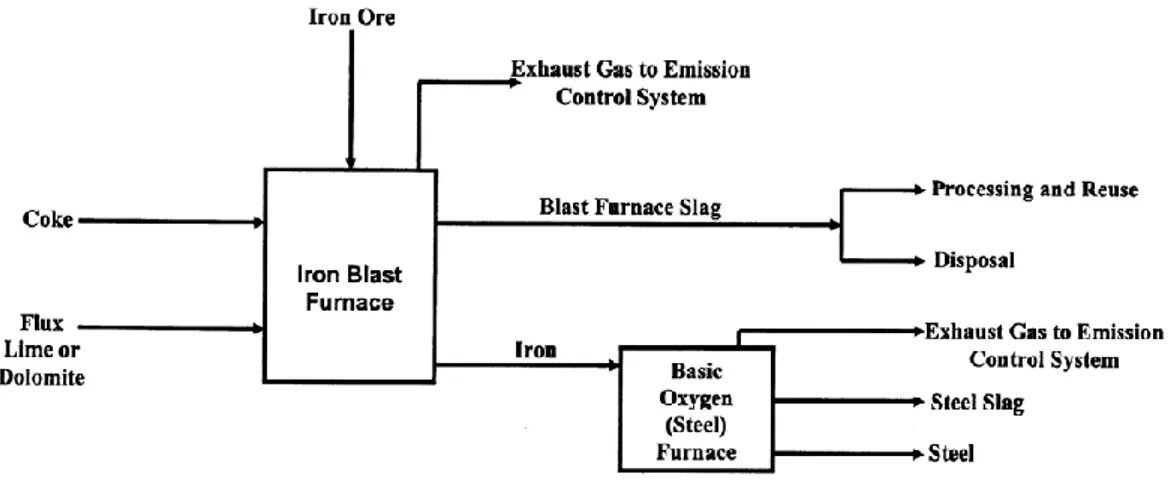
molten slag, which absorbs much of the sulfur from the charge, comprises about 20% by mass of iron production (Monshi, 1999). Production process is schematically presented below:
Figure 3.2 : General schematic of blast furnace operation and blast furnace slag production (TFHR, 2004)
BFS can replace Portland cement (PC) as binder by reacting with the alkali product of hydrated PC Ca(OH)2 in alkali activations or pozzolanic reactions. By using blast
furnace slag instead of PC CO2 emissions can be decreased. It has cementitious
properties After that manufacture of GBFSC has substantially increased due to greater emphasis on energy conservation, utilization of waste materials and certain technical advantages over ordinary PC such as higher resistance to aggressive conditions.
20
Blast furnace slag has been widely used as a successful replacement material for PC, improving some properties and bringing economic benefits.
3.2.1 Air-cooled blast furnace slag
If the liquid slag is poured into beds and slowly cooled under ambient conditions, a crystalline structure isformed and a hard lump slag is produced, which can subsequently be crushed and screened. It has angular, roughly cubical, and has textures ranging from rough, vesicular (porous) surfaces to glassy (smooth) surfaces with conchoidal fractures.
3.2.2 Expanded or foamed blast furnace slag
If the molten slag is cooled and solidified by adding controlled quantities of water, air, or steam, the process of cooling and solidification can be accelerated, increasing the cellular nature of the slag and producing a lightweight expanded or foamed product. Foamed slag is distinguishable from air-cooled blast furnace slag by its relatively high porosity and low bulk density Expanded blast furnace slag (EBFS) has angular, roughly cubical shape, and has a texture that is rougher than that of air-cooled slag. The porosity of expanded blast furnace slag aggregates is higher than air cooled slag aggregates. The bulk relative density of expanded slag is difficult to determine accurately, but it is approximately 70 percent of that of air-cooled slag. Typical compacted unit weights for expanded blast furnace slag aggregates range from 800 kg/m3 (50 lb/ft3) to 1040 kg/m3 (65 lb/ft3).
3.2.3 Pelletized blast furnace slag
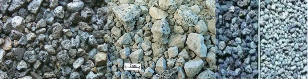
This product is formed by cooling the molten slag using water to produce a lightweight aggregate that can be used for high fire-rated concrete masonry and lightweight fill applications over marginal soils. It is perfectly suited for aggregate in lightweight concrete masonry, lightweight ready-mix concrete and lightweight precast concreted due to its reduced-weight. Types of blast furnace slag are shown in Figure 3.3
21
Figure 3.3 : a) Blast furnace slag b) Air-cooled blast furnace slag c) Pelletized blast furnace slag
3.3 Electric arc furnace slag
EAF slags are a by-product of the steel-making process. They are obtained by a treatment process based on controlled solidification and subsequent crushing of slags from scrap melting in the electric arc furnace. After every crushing step, magnetic belts extracted the newly freed iron particles and the slags were screened in different grain sizes, becoming artificial aggregates. The main chemical constituents of EAF slags are FeO (22-60%), CaO (6-48%), SiO2 (9-32%), Al2O3 (3-14%) and MgO (3-15%). The
oxide composition values in literature are given in table below Table 3.1.
Table 3.1: The oxide composition values in literature (Autelitano and Giuliani, 2015)
Parameters Literature Values
Calcium Oxide (CaO) % 6-48 Silica Dioxide (SiO2)% 9-32
Aluminum Oxide (Al2O3)% 3-14
Magnesium Oxide (MgO)% 3-15 Iron (II) Oxide (FeO)% 21-48 Manganese (II) Oxide (MnO)% 1-16 Titanium Dioxide (TiO2)% 0-1
Phosphorus Pentoxide 0-2
Chromium (III) Oxide (Cr2O5)% 0-2
Sulfur (S)% -
Chromium (Cr)% -
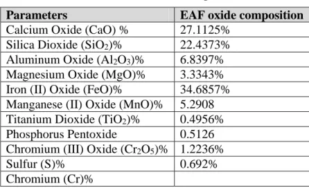
The oxide composition of EAF slag was determined using X-ray fluorescence (XRF) analysis. Table 3.2 shows the oxide composition of EAF slag used in our experiments. Major oxide found are FeO, CaO and SiO2.
22
Table 3.2 : EAF oxide composition
Parameters EAF oxide composition
Calcium Oxide (CaO) % 27.1125% Silica Dioxide (SiO2)% 22.4373%
Aluminum Oxide (Al2O3)% 6.8397%
Magnesium Oxide (MgO)% 3.3343% Iron (II) Oxide (FeO)% 34.6857% Manganese (II) Oxide (MnO)% 5.2908 Titanium Dioxide (TiO2)% 0.4956%
Phosphorus Pentoxide 0.5126 Chromium (III) Oxide (Cr2O5)% 1.2236%
Sulfur (S)% 0.692%
Chromium (Cr)%
3.4 Sand
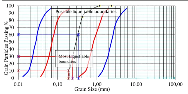
The sandy soil used in experiments belongs to boundaries of most liquefiable soil shown in Figure 3.4. Physical properties of soil were estimated by some laboratory test done in our laboratory. For determination of friction angle and cohesion coefficient direct shear test was conducted. Specific gravity and unit weight were determined by specific gravity test and unit weight test. Physical properties are shown in Table 3.3.
Table 3.3 : Physical properties of sand Physical Properties Values
Unit Weight 14kN/m3
Cohesion Coefficient 0 Specific Gravity 2.65 Friction Angle 33o
23
Figure 3.4 : Limits in the gradation curve seperating liquefiable soils (modified from Tsuchida, 1970)
3.5 Roof tile powder
The major constituents of roof tile powder are SiO2, Fe2O3, Al2O3 and MgO. Roof tile
powder has pozzolanic activity. A pozzolano material is rich in silica and alumina which itself posses little or no cementitious properties but in presence of moisture, chemically react with CaOH at ordinary temperatures and form compounds having cementitious properties. It is natural, smooth and ductile. It is used also for agriculture purpose and to give color to roof. It has a unit weight of 11 kN/m3 and it has grain size of of 1- 4 mm in ranges.
3.6 Diatomite
Diatomite is a near pure sedimentary deposit made up almost of silica. The Greeks first used diatomite over 2000 years ago in pottery and brick. Exists many diatomite deposits throughout the world. Diatomite has high porosity, high permeability, small particle-size, large surface area, low thermal conductivity, for this that makes it suitable for a wide range of industrial applications (Inglethorpe, 1993). Typical chemical analyses of pure diatomite’s generally is composed of 70-80% silica (SiO2),
porosity 85%, unit weight 2-4 kN/m3, and contain other elements like TiO
2, Al2O3,
Fe2O3, MnO, MgO, CaO, Na2O, K2O, P2O5.The four main usages of diatomite in the
0 10 20 30 40 50 60 70 80 90 100 0,01 0,10 1,00 10,00 100,00 Gr ain P artic les Passi ng % Grain Size (mm) Possible liquefiable boundaries
Most Liquefiable boundries
24
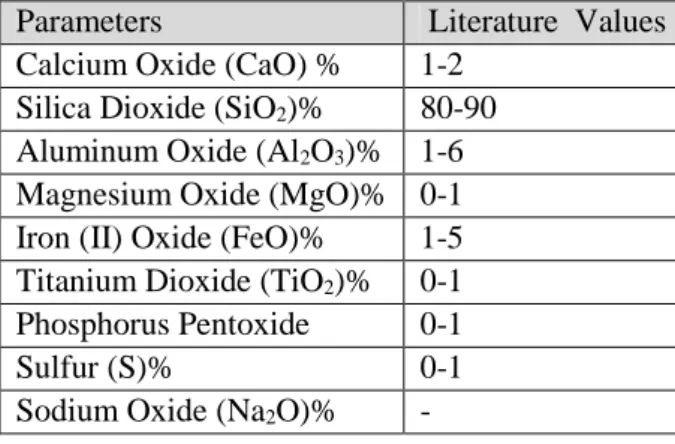
United States during 2013 were filter media (56%), cement additive (15%), fillers (14%), absorbents (13%) and other (2%). Literature values of chemical composition are given in Table 3.4. Physical characteristics of pure diatomite are like chalk and usually white gray. Particle size of diatomite varies from 5 to 1000 µm, but the dominant size is between 50 to 100 µm.
Table 3.4 : Literature values of chemical composition (URL 1) Parameters Literature Values
Calcium Oxide (CaO) % 1-2 Silica Dioxide (SiO2)% 80-90 Aluminum Oxide (Al2O3)% 1-6 Magnesium Oxide (MgO)% 0-1 Iron (II) Oxide (FeO)% 1-5 Titanium Dioxide (TiO2)% 0-1 Phosphorus Pentoxide 0-1
Sulfur (S)% 0-1
Sodium Oxide (Na2O)% -
3.7 Sulfuric acid
It is soluble in water in all preparations with the evolution of a large amount of heat. It is drying and dehydrating agent, it can extract water from compounds. Sulfuric acid is very reactive and corrosive. It can react with water, alkalies, with carbonates and bicarbonates and metals. Moreover, it is a moderately strong oxidizing agent. Sulfuric acid is the world's major volume industrial chemical. It is mainly used in the production of phosphate fertilizers. Furthermore, it is used to manufacture explosives, other acids, dyes, glue, wood preservatives, automobile batteries, in the purification of petroleum, the pickling of metal, copper smelting, electroplating, metal work, and the production of rayon and film. In Table 3.5 are given physical properties of H2SO4.
Table 3.5 : Physical properties of sulfuric acid (URL 2) Physical Properties of Sulfuric Acid
Melting Point 10.35°C Boiling Point 315-338°C Vapor Density 3.4 Specific Gravity 1.84 Molecular Formula H2SO4
25 3.8 Environmental impact
Reuse of slag is turning on to a core content of sustainable development. Much more efforts must be done in order to increase the recycling attitudes of society and to cut down the waste landfill disposal. Industrial waste management is one of the major environmental problems in Turkey and all over the world. Therefore, recycling and reuse of industrial wastes play vital role both in solving industrial waste problem and in getting benefit from it. The use of slag in cement manufacturing considerably reduces CO2 emission and the energy needed. The use of slag as aggregate decrease
the need for virgin material and the energy use and emission produced during the mining, processing and transportation of those materials fit from it. Usage of waste material as admixtures such as electric arc furnace slag, brick dust, fly ash, silica fume can reduce environmental impact. We can save natural resources and protect the human health by using industrial co-products. In fact, the scrap steel slag does not only take up a lot of land but also causes environmental pollution without treatment. Increase in steel slag production seems to be a serious problemalso in the future.
27 4. SOIL PREPARATION & EXPERIMENTS
For unconfined compressive tests, waste materials (electric arc furnace slag, roof tile powder, diatomite) are mixed at different proportions with sand and chemical additives. Optimum mixing proportion will be tested under 1-D shaking table to investigate liquefaction resistance which is the most phenomena occurring at sandy soils. Firstly, physical properties of sandy soil were determined. Sieve analysis, direct shear test and specific gravity testswereconducted. In order to determine chemical composition of electric arc furnace slag, XRF analysis was done and results were given in Chapter 3.
4.1 Sieve analysis
Particle size distribution of coarse-grained soils is obtained by conduction of sieve analysis. The test used to define particle size distribution was done based on ASTM D422 standards. A stack of sieves was placed on sieve shaker and shaken for 10 minutes. (Fig 4.1). Sieve analysis was done for sand and EAF slag in order to obtain the required particle size that will be used in experiments.
Figure 4.1: Stack of sieves
Sand particles retained on sieve number 60 and 120 are used in our experiments. Sand used has a particle size varies from (250 µm- 425 µm). Electric arc furnace slag has a particle size of 150 µm.
28 4.2 Specific gravity test
Specific gravity (Gs) is a physical parameter of soil calculated by the ratio of weight of soil solids to the weight of water of equal volume. The specific gravity of coarse grained soils ranges form 2.6-2.8 but fine grain soils have less Gs. The test is conducted base on ASTM D854.
Value of specific gravity obtained is: Gs=2.63 Figure 4.2 illustrates dessicator and pycnometer.
Figure 4.2 : Dessicator and pycnometer
4.3 Wet sieve analysis
The ASTM D1140 standard test method was used to obtain clean sand. The sand obtained after shaking on sieve shaker will be washed through sieve with diameter 74 µm. The soil was washed through sieve with diameter 74 µm under tap until the effluent is clear (Figure 4.3). After that, it was dried in the oven, at 105o C for 24 hours.
29 4.4 Direct shear test
Direct shear testing (ASTM D3080) is preformed to get shear strength properties of soils under drain loading conditions cohesion (c') and friction angle (Ø). Generally is used to test cohesionless soils. Results are expressed in terms of Mohr-Coulomb failure envelope (Figure 4.4), shear strength (τf) and normal stress (σf). Since the test is
performed for cohesionless soils, cohesion (c') is nearly equal to zero.
Figure 4.4 : Mohr-Coulomb failure envelope
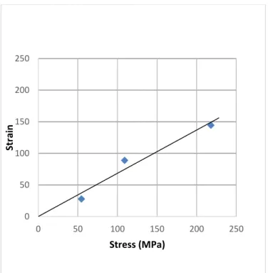
Friction angle and cohesion coefficient of used sandy soil were 33o and 0 respectively. Figure 4.5 shows stress-strain curve obtained from direct shear test.
Figure 4.5 : Direct shear test 0 50 100 150 200 250 0 50 100 150 200 250 Str ai n Stress (MPa)
30 4.5 Unconfined compressive strength test
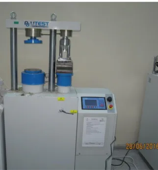
Unconfined compressive strength test is done to determine strength of soil. Each mixture is tested under axial load and maximum load, and stress strain curve is obtained for each combination. Figure 4.6 illustrates unconfined compression machine.
Unconfined compression test was carried out separately for each mixture. Cylindrical samples with dimensionheight and diameter 100 mm x 50 mm were prepared in laboratory conditions. After one day, samples were unmolded and cured in air conditions for 7, 21 and 28 days. Tests results and failure type will be discussed in Chapter 5.
Figure 4.6 : Unconfined compressive strength test machine
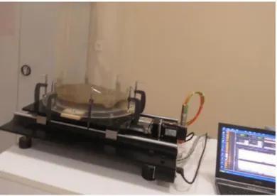
4.6 1-D shaking table test
Optimum mixing proportion obtained will be tested on 1-D shaking table. The shaking table test is done to investigate the response of sandy soils under dynamic loads. A specimen is set up on the table which can be driven by actuators as shown in In order to hold the physical model, a rigid box was used. Figure 4.7 shows the plan view of physical model. Ground motion records used are most known earthquakes (El Centro, 1940; Niigata, 1964; Loma Prieta, 1989; Northridge, 1994; Kobe, 1995; Kocaeli, 1999). 1-D shaking table has a capacity of 35 kg and 1-g acceleration.
31
Figure 4.7 : 1-D shaking table 4.7 Methodology steps
Firstly, EAF slag was mixed in different proportions with water. Cylindrical molds were prepared. After, unmolded samples were cured in the air. Behavior of EAF slag mixtures was investigated under tensiles loads. Samples contained 5, 10, 15% amount of water. Low bonding capacity was observed. After observation of this effect it was proposed usage of chemical additives to provide a better connection between components. As chemical additive, H2SO4 was added to mixtures prepared. After that,
n instead of H2SO4, acetic acid was added to decrease the cost of materials. Addition
of H2SO4 activated the slag that’s why it is used in all type of mixtures. Besides that,
in order to increase the strength of sandy soils, waste material roof tile powder and natural material diatomite was added to prepare the mixtures. Reddy et al., (2006) reported that cementitious properties of steel slag tend to increase with an increase in their basicity. Based on this, in some of mixtures prepared Na2SO4 and Na2S salts were
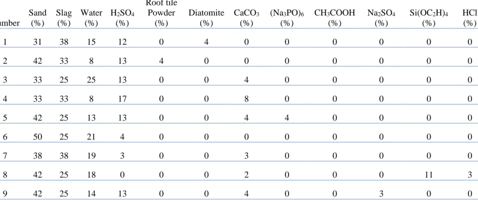
added. Compressive strength of all the mixtures were investigated. In Table 4.1 are given all mixture type and mixing proportions of constituents used.
32
Table 4.1 : Mixing proprotions of components by weight Number Sand (%) Slag (%) Water (%) H2SO4 (%) Roof tile Powder (%) Diatomite (%) CaCO3 (%) (Na3PO)6 (%) CH3COOH (%) Na2SO4 (%) Si(OC2H)4 (%) HCl (%) 1 31 38 15 12 0 4 0 0 0 0 0 0 2 42 33 8 13 4 0 0 0 0 0 0 0 3 33 25 25 13 0 0 4 0 0 0 0 0 4 33 33 8 17 0 0 8 0 0 0 0 0 5 42 25 13 13 0 0 4 4 0 0 0 0 6 50 25 21 4 0 0 0 0 0 0 0 0 7 38 38 19 3 0 0 3 0 0 0 0 0 8 42 25 18 0 0 0 2 0 0 0 11 3 9 42 25 14 13 0 0 4 0 0 3 0 0