T.C.
SELÇUK UNIVERSITY
THE GRADUATE SCHOOL OF NATURAL SCIENCES
FRACTURE BEHAVIORS OF EPOXY ADHESIVELY BONDED COMPOSITE JOINTS REINFORCED WITH GRAPHENE AND NYLON 6.6 NANOFIBERS
Mehmet AÇIK Ph.D. Thesis
Depertment of Mechanical Engineering
September-2017 KONYA All Rights Reserved
Mehmet AÇIK tarafından hazırlanan “Grafen ve Naylon 6.6 Nanoelyaf ile Güçlendirilmiş Epoksi ile Yapıştırılan Kompozit Bağlantıların Kırılma Davranışları” adlı tez çalışması 06/09/2017 tarihinde aşağıdaki jüri tarafından oy birliği ile Selçuk Üniversitesi Fen Bilimleri Enstitüsü Makine Mühendisliği Anabilim Dalı’nda DOKTORA TEZİ olarak kabul edilmiştir.
Jüri Üyeleri İmza
Başkan
Prof. Dr Necmettin TARAKÇIOĞLU ………..
Danışman
Prof. Dr. Ahmet AVCI ………..
Üye
Prof. Dr. Ömer Sinan ŞAHİN ………..
Üye
Yrd. Doç. Dr. Ali ÖZTÜRK ………..
Üye
Yrd. Doç. Dr. Mürsel EKREM ………..
Yukarıdaki sonucu onaylarım.
Prof. Dr. Mustafa YILMAZ
FBE Müdürü
Bu tez çalışması, Türkiye Bilimsel ve Teknolojik Araştırma Kurumu (TÜBİTAK) tarafından 215M777 nolu proje ve Selçuk Üniversitesi Bilimsel Araştırmalar Koordinatörlüğü tarafından ise 15201087 nolu proje ile desteklenmiştir.
I hereby declare that all information in this document has been obtained and presented in accordance with academic rules and ethical conduct. I also declare that, as required by these rules and conduct, I have fully cited and referenced all material and results that are not original to this work.
TEZ BİLDİRİMİ
Bu tezdeki bütün bilgilerin etik davranış ve akademik kurallar çerçevesinde elde edildiğini ve tez yazım kurallarına uygun olarak hazırlanan bu çalışmada bana ait olmayan her türlü ifade ve bilginin kaynağına eksiksiz atıf yapıldığını bildiririm.
Mehmet AÇIK 06.09.2017
iv
ABSTRACT
Ph.d. THESIS
FRACTURE BEHAVIORS OF EPOXY ADHESIVELY BONDED COMPOSITE JOINTS REINFORCED WITH GRAPHENE AND NYLON 6.6 NANOFIBERS
Mehmet AÇIK
THE GRADUATE SCHOOL OF NATURAL AND APPLIED SCIENCES OF SELÇUK UNIVERSITY
THE DEGREE OF DOCTOR OF PHILOSOPHY IN MECHANICAL ENGINEERING
Advisor: Prof. Ahmet AVCI 2017, 218 Pages
Jury
Prof. Ahmet AVCI
Prof. Necmettin TARAKÇIOĞLU Prof. Ömer Sinan ŞAHİN
Asst. Prof. Ali ÖZTÜRK Asst. Prof. Mürsel EKREM
In this dissertation, fracture behavior of epoxy adhesives reinforced with electrospun nylon 6.6 nanofiber mats consolidated with graphene was studied. Within this work; firstly, neat nylon 6.6 and including graphene (1, 3, and 5 % by weight) nylon 6.6 nanofiber mats were produced by electrospinning method. Secondly, prepreg composite coupons were bonded to each other with neat epoxy and epoxy reinforced with electrospun nylon 6.6 nanofiber mats (neat/including graphene). Thirdly, Single Lap Shear, Double Cantilever Beam and End Notched Flexure tests were studied with those test samples. In carried out tests, fracture behavior of the adhesively bonded composite joints was analyzed, and shear strength and fracture toughness (mode-I and mode-II) were examined. The mechanical properties of Single Lap Shear test coupons in accordance with ASTM D 5868 and Double Cantilever Beam in accordance with ASTM D 5528 and End Notched Flexure test coupons in accordance with ASTM D 7905 standards were checked respectively.
The characteristics of test samples were investigated by using Fourier Transform Infrared Spectroscopy (FT-IR), Thermogravimetric Analysis (TGA)/Differential Thermal Analysis (DTA), Scanning Electron Microscopy (SEM) and Transmission Electron Microscope (TEM). The dispersion of graphene in electrospun nanofiber, fracture surface morphologies of neat nylon 6.6 nanofibers and nylon 6.6 nanofibers consolidated with various rates of graphene were studied by using SEM and TEM. Moreover, in order to make assessments that were more reasonable, issues affecting fracture surface and fracture toughness were also checked.
It was determined that the shear strength and fracture toughness of graphene reinforced nylon 6.6 nanomats were significantly increased. In addition, it was verified by the tests that the most optimal option was the addition of 3% wt. of graphene to the nanomats.
v
ÖZET
DOKTORA TEZİ
GRAFEN VE NAYLON 6.6 NANOELYAF İLE GÜÇLENDİRİLMİŞ EPOKSİ İLE YAPIŞTIRILAN KOMPOZİT BAĞLANTILARIN KIRILMA DAVRANIŞLARI
Mehmet AÇIK
Selçuk Üniversitesi Fen Bilimleri Enstitüsü Makine Mühendisliği Anabilim Dalı
Danışman: Prof. Dr. Ahmet AVCI 2017, 218 Sayfa
Jüri
Prof. Dr. Ahmet AVCI
Prof. Dr. Necmettin TARAKÇIOĞLU Prof. Dr. Ömer Sinan ŞAHİN
Yrd. Doç. Dr. Ali ÖZTÜRK Yrd. Doç. Dr. Mürsel EKREM
Bu tez çalışmasında, grafen takviyeli elektrospin naylon 6.6 nanoelyaf keçelerle güçlendirilmiş epoksi yapıştırıcıların yapıştırmalı kompozit bağlantılardaki kırılma davranışları çalışılmıştır. Çalışma kapsamında ilk olarak saf naylon 6.6 nanoelyaf ve grafen (ağırlıkça % 1, 3 ve 5) ihtiva eden naylon 6.6 nanoelyaf keçeler elektroeğirme yöntemiyle üretilmiştir. İkinci aşamada, prepreg kompozit test numuneleri katıksız epoksi ve elektrospin naylon 6.6 nanoelyaf keçelerle (saf ve grafen takviyeli) güçlendirilmiş epoksi yapıştırıcılar ile yapıştırılmıştır. Üçüncü aşamada üretilen test numuneleri ile Tek Taraflı Bindirme (Single Lap Shear-SLS), Çift Konsol Kiriş (Double Cantilever Beam-DCB) ve Çentikli Üç Nokta Eğme (End Notched Flexure-ENF) testleri yapılmıştır. Yapılan testlerde yapıştırma bağlantılarındaki kırılma davranışları analiz edilmiş ve oluşturulan bağlantıların kayma dayanımları ve kırılma toklukları (Mod-I ve Mod-II) incelenmiştir. Mekanik özelliklerin belirlenmesi maksadıyla SLS testleri ASTM D 5868, DCB testleri ASTM D5528, ENF testleri ise ASTM D 7905 standardına uygun olarak gerçekleştirilmiştir.
Test numunelerinin karakterizasyonu Fourier Dönüşümlü Infrared Spektrometre (FT-IR), Termogravimetrik Analiz (TGA)/Diferansiyel Termal Analiz (DTA), Taramalı Elektron Mikroskopisi (SEM) ve Taramalı Elektron Mikroskobu (TEM) ile incelenmiştir. Ayrıca, daha hassas değerlendirmeler yapabilmek maksadıyla kırılma yüzeyi ve kırılma tokluğuna etki eden hususlar kontrol edilmiştir.
Yapılan testlerde, grafenle takviyeli nylon 6.6 nanoelyaf keçelerin kırılma toklukları ile kayma dayanımının önemli ölçüde artırıldığı görülmüştür. Ayrıca, nanoelyaf keçelere ağırlıkça %3 grafen takviyesinin en uygun çözüm olduğu testlerle doğrulanmıştır.
Anahtar Kelimeler: Çift konsol kiriş, çentikli üç nokta eğme, elektroeğirme, tek taraflı bindirmeli bağlantı, yapıştırıcı.
vi
ACKNOWLEDGEMENTS
Firstly, I would like to express my sincere gratitude and appreciation to my advisor Prof. Ahmet AVCI for his tireless support, guidance, and energy during my entire time of study.
Besides my advisor, I would like to give my special thanks to my lab mates Asst. Prof. Mürsel EKREM and Dr.Okan DEMİR who provided me an opportunity to work with them. Without their invaluable support, encouragement and patience I could not have imagined finalizing my experimental works, calculations, and plotting of the graphs.
I also extend my sincere thanks to Celal ÖĞÜTOĞULLARI (CEO of ÇAN Joint Venture), Asst.Prof. Gökçe DARA (Materials and Ballistic Protection Technologies Manager at ROKETSAN Missiles Inc.), and Emre ERDİNÇ (Avionics Systems Chief at Turkish Aerospace Industries Inc.) not only for manufacturing of experimental equipment and test pieces but also for their suggestions, and guidance to follow the methodology in the field.
In addition, thanks to Scientific and Technological Research Council of Turkey (TÜBİTAK) and Selçuk University Coordinator of Scientific Research projects (BAP), which provide financial support through the projects 215M777 and 15201087 respectively, for the procurement, production and examination of test samples.
Finally, with the deepest sense of gratitude, I would like to offer my special thanks to my extended family, especially my wife, son, and daughter for their support, encouragement, and patience.
Mehmet AÇIK KONYA-2017
vii
TABLE OF CONTENTS
ABSTRACT ... iv
ÖZET ... v
ACKNOWLEDGEMENTS... vi
TABLE OF CONTENTS ...vii
SYMBOLS AND ACRONYMS ...xii
1 INTRODUCTION ... 1
1.1 Framework and Research Objective ... 2
1.2 Structure of the Thesis ... 3
2 LITERATURE REVIEW ... 4
2.1 Adhesively Bonded Joints ... 4
2.2 Electrospinning and Reinforcement of Electrospun Nylon with Graphene ... 7
2.3 Fracture Behavior of the Adhesively Bonded Joints ... 9
2.4 Adhesives ... 11
2.4.1 Adhesive and Adhesive Bonding ... 11
2.4.2 Advantages and Disadvantages of Adhesive Bonding ... 14
2.4.3 Types of Adhesively Bonded Joint Designs ... 16
2.4.4 Types of Stress... 18
2.4.4.1 Tensile Stress ... 19
2.4.4.2 Shear Stress... 19
2.4.4.3 Peel Stress ... 19
2.4.4.4 Cleavage Stress ... 20
2.4.5 Adhesive Bonding Theories ... 20
2.4.5.1 Mechanical Interlocking Theory ... 22
2.4.5.2 Electrostatic Theory ... 23
2.4.5.3 Diffusion Theory ... 23
2.4.5.4 Absorption Theory ... 24
2.4.5.5 The Weak Boundary Layer Theory ... 24
2.4.5.6 Chemical Bonding Theory ... 25
2.4.5.7 Wetting Theory ... 26
2.4.6 Adhesive Bonding Failures ... 29
2.4.7 Application of Adhesives ... 30
viii 2.4.7.2 Automotive Industry... 32 2.4.7.3 Marine Industry ... 33 2.4.7.4 Electrical Industry ... 33 2.4.7.5 Medical Industry ... 34 2.4.8 Adhesive Classification ... 34 2.4.8.1 Function ... 35 2.4.8.2 Chemical composition ... 35 2.4.8.3 Method of curing ... 36 2.4.8.4 Physical form ... 37 2.4.8.5 Others ... 37 2.4.9 Epoxies ... 38
2.4.9.1 Synthesis of Epoxy Resin ... 39
2.4.9.2 Epoxy Resin and Adherents ... 41
2.5 Composites ... 43
2.6 Nanotechnology ... 46
2.6.1 Carbon nanotubes (CNTs) ... 48
2.6.2 From Graphite to Graphene ... 50
2.6.2.1 Polymer Nanocomposites ... 54 2.6.2.1.1 In-situ Polymerization ... 54 2.6.2.1.2 Solution Blending ... 55 2.6.2.1.3 Melt Compounding ... 56 2.6.2.2 Graphene versus CNTs ... 57 2.7 Surface Preparation ... 59
2.7.1 Importance of Surface Preparation ... 60
2.7.2 Surface Treatment Methods ... 61
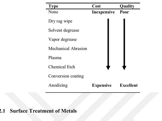
2.7.2.1 Surface Treatment of Metals ... 62
2.7.2.2 Surface Treatment of Plastics ... 63
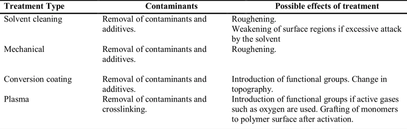
2.7.2.2.1 Surface cleaning ... 64 2.7.2.2.2 Mechanical treatment ... 64 2.7.2.2.3 Corona treatment ... 65 2.7.2.2.4 Flame treatment ... 65 2.7.2.2.5 Plasma treatment ... 66 2.7.2.2.6 Chemical Etching ... 66
ix
2.8 Electrospinning ... 67
2.8.1 Principle and Mechanism of Electrospinning ... 68
2.8.2 Regions in an Electrospinning Jet ... 71
2.8.2.1 1st Region: Taylor Cone ... 71
2.8.2.2 2nd Region: Stable Region (Straight Jet) ... 72
2.8.2.3 3rd Region: Instable Region (Whipping Jet) ... 72
2.8.3 Parameters of Electrospinning ... 73
2.8.4 Electrospinning and Nylon 6.6 ... 78
2.9 Analysis of Adhesively Bonded Joints ... 80
2.9.1 Analytical Solutions ... 81
2.9.2 Numerical Solutions ... 82
2.9.2.1 Milestones in the Analysis ... 82
2.9.2.1.1 Rigid Adherent Stress Analysis ... 83
2.9.2.1.2 Volkersen’s Analysis ... 83
2.9.2.1.3 Analysis of Goland and Reissner ... 85
2.9.2.1.4 Analysis of Ojalvo and Eidinoff ... 86
2.9.2.1.5 Hart-Smith’s Analysis ... 87
2.9.2.1.6 Analysis of Bigwood and Crocombe ... 88
2.9.2.2 Analysis of Adams ... 88
2.10 Test Types of Adhesively Bonded Joints... 89
2.10.1 Single LAP Joints (SLJ) ... 90
2.10.2 Double Cantilever Beam (DCB) ... 92
2.10.2.1 Modified Beam Theory (MBT) ... 94
2.10.2.2 Compliance Calibration Method ... 95
2.10.2.3 Modified Compliance Calibration (MCC) Method ... 96
2.10.3 End Notched Flexure (ENF) ... 97
2.10.3.1 Compliance Calibration Method (CCM) ... 98
2.10.3.2 Corrected Beam Theory (CBT) ... 99
2.10.3.3 Compliance-Based Beam Theory (CBBT) ... 99
2.11 Characterization and Surface Analysis Techniques... 100
2.11.1 Transmission Electron Microscope (TEM) ... 101
2.11.2 Scanning Electron Microscopy (SEM)... 101
x
2.11.4 Fourier Transform Infrared Spectroscopy (FT-IR) ... 102
2.11.5 Differential Scanning Calorimetry (DSC) ... 103
2.11.6 Differential Thermal Analysis (DTA) ... 103
2.11.7 Thermo Gravimetric Analysis (TGA) ... 104
3 MATERIAL AND METHOD ... 105
3.1 Properties of the Materials ... 106
3.1.1 Adhesive ... 106
3.1.2 Composite ... 106
3.1.3 Graphene ... 107
3.1.4 Nylon 6.6 ... 107
3.2 Preparation of the Materials ... 108
3.2.1 Adhesive Preparation ... 108
3.2.2 Composite Surface Preparation... 108
3.2.3 Solution Preperation ... 110
3.2.4 Preparation of Electrospun Nanomats ... 111
3.2.5 Preparation of Adhesively Bonding Test Specimens ... 112
3.2.5.1 Single LAP Joints Test Specimens ...113
3.2.5.1.1 Adherent Preparation ... 113
3.2.5.1.2 Adhesive Application and Assembly ... 114
3.2.5.1.3 Curing and Specimen Cleaning ... 116
3.2.5.1.4 Testing ... 117
3.2.5.2 Double Cantilever Beam Test Specimens ...119
3.2.5.2.1 Adherent Preparation ... 119
3.2.5.2.2 Adhesive Application and Assembly ... 119
3.2.5.2.3 Curing and Specimen Cleaning ... 121
3.2.5.2.4 Testing ... 122
3.2.5.3 End Notched Flexure Test Specimens ...124
3.2.5.3.1 Adherent Preparation ... 124
3.2.5.3.2 Adhesive Application and Assembly ... 124
3.2.5.3.3 Curing and Specimen Cleaning ... 126
xi
4 RESULTS AND DISCUSSION ... 129
4.1 Characterization of Bonded Surfaces ... 129
4.1.1 SEM Images of Electrospun Nylon 6.6 Nanofibers ... 130
4.1.2 TEM Images of Electrospun Nylon 6.6 Nanofibers ... 132
4.1.3 FT-IR Spectroscopy ... 134
4.1.3.1 FT-IR Spectroscopy of Graphene/Nylon 6.6 Nanomats ...134
4.1.3.2 FT-IR Spectroscopy of Graphene/Nylon 6.6 Nanomats Blend with Epoxy ...135
4.1.4 DTA Analysis ... 136
4.1.4.1 DTA Analysis of Electrospun Graphene/Nylon 6.6 Nanomats ...137
4.1.4.2 DTA Analysis of of Electrospun Graphene/Nylon 6.6 Nanomats Blend with Epoxy ...138
4.1.5 TGA Analysis ... 139
4.1.5.1 TGA Analysis of Electrospun Nylon 6.6 Nanomats ...140
4.1.5.2 TGA Analysis of of Graphene/Nylon 6.6 Nanomats Blend with Epoxy ...140
4.2 Mechanical Tests ... 141
4.2.1 Shear Strength of Single-Lap Joints ... 142
4.2.2 Analysis of Fracture Toughness under Mode-I Loadings ... 149
4.2.3 Analysis of Fracture Toughness under Mode-II Loadings ... 162
4.3 Fracture surface analysis ... 169
5 RESULTS AND SUGGESTIONS ... 178
5.1 Results ... 178
5.2 Suggestions ... 179
REFERENCES ... 181
xii
SYMBOLS AND ACRONYMS Symbols Unit
a : mm Crack length
b : mm Specimen width
δ : mm Displacement
: MPa Shear strength
: mm/mm Shear displacement
: MPa Shear strain
GIC : kJ/m2 Critical strain energy release rate (Mod I)
GIIC : kJ/m2 Critical strain energy release rate (Mod II)
h : mm Specimen height
l : mm Specimen length
P : N Applied load
Acronyms
ABJs : Adhesively Bonded Joints
ASTM : American Society for Testing and Materials SEM : Scanning Electron Microscopy
TEM : Transmission Electron Microscope TGA : Thermogravimetric Analysis DTA : Differential Thermal Analysis
FT-IR : Fourier Transform Infrared Spectroscopy SLJs : Single Lap Joints
DCB : Double Cantilever Beam ENF : End Notch Flexure PA6.6 : Polyamide 6.6
1 INTRODUCTION
Although adhesion simply means bonding two or more particles or surfaces to each other, there has been a huge iceberg behind this definition. Because nobody exactly knows, where and when the history of adhesives began. Nevertheless, footprints that show it dates back to the history of human beings. That is why we set out our journey from ancient times.
In the old days, the almost most of things used as adhesives were derived from animals or plants by natural ways or techniques. As humankind evolved, he begins to observe and discover what is going on around himself. He examines insects and birds building and repairing of their nests with mud and clay. He tries to copy or imitate what he learned from animals. Over time, he has improved what he adopted from his environment and begun to use them in different areas with different techniques. He begins to mix mud and clay with straw and other plant particles to make them much stronger. These mixtures are the ancestors of first composite materials. Then he ties sharp stones and sticks with vines and natural fibers to make tools and weapons, utilizes plant resin to attach broken pottery to each other (Pizzi and Mittal, 2003).
The use of these natural adhesives lasted the twentieth century. Since about 1900s, adhesives based on synthetic adhesives were introduced to the humankind. Then scientists, engineers, academics, and industry began to try new bonding methods and techniques to make the structures cheaper, lighter, stronger, and user-friendly. Due to the need and demand for these new kinds of structures, with in a period of one hundred years adhesives have begun to be used in a way never seen before.
Today adhesives are used in a wide range of applications. These applications range from simple sticky tapes to airplane fuselages and from envelopes to complex structures. Using adhesives instead of such conventional joining techniques as soldering, welding, nailing, riveting, and bolting gives a more uniform stress distribution, increase the designers’ freedom, production rates, and reduces the structures’ weight, machining operations and corrosion. These challenging advantages encourage engineers, academics, and industry to focus on adhesives and Adhesively Bonded Composite Joints (ABJs) more deeply (Peckham, 1992).
Although engineers, academics, and industry utilize adhesive techniques more extensively, adhesion science has certain drawbacks to overcome and some questions to be answered days to come.
Because expectation from adhesives is not only to stick two or more adherents to one another but also to make a uniform structure that, endure harsh environmental effects. Modern technological requirements from ABJs are long service life span (resistant to vibration, fatigue,
and corrosion), lightweight (superior strength/stiffness to weight ratios), safety (crashworthy, strong damage tolerance and high-energy absorption capabilities), and various use of application (freedom of design and esthetic) (da Silva et al., 2011).
In order to achieve these necessities scientists are in search of new techniques. With its increased commercial availability and reduced prices nanofillers (nanofibers, nanoparticles, nanotubes, etc.) reinforced fibers has gone beyond in this area.
1.1 Framework and Research Objective
As stated earlier, despite numerous works have been done to understand mechanical behavior and properties of adhesively bonded composite joints; there have been still gaps to be filled and new techniques to be conducted. Since the development and commercialization of nano-sized particles, the most of the works has begun to focus on nano-reinforced adhesives. Those who have worked on this hot subject try to bond two or more adherents with adhesives that host nanoparticles. Nevertheless, to enhance the strength and fracture toughness of ABJs, there are several of different techniques that have to be explored by the scientific community.
The primary objective of this thesis is:
To investigate the fracture behavior of composite joints bonded to each other with electrospun nylon 6.6 nanofiber mats reinforced with various weight of graphene by experimental methods,
To assess the effects and influence of electrospun nylon 6.6 nanofiber mats on the adhesion strength of ABJs,
To compare the results of epoxy, electrospun neat nylon 6.6 nanofiber and electrospun nylon 6.6 nanofiber mats reinforced with various weight of graphene.
In order to achieve this objective, the work is briefly broken down as follows:
Surfaces of prepreg composite adherents will be treated in accordance with ASTM D2093 (Standard, 2017),
Nylon 6.6 nanofiber mats reinforced with various weight of graphene will be produced by electrospinning technique,
Graphene reinforced electrospun nylon 6.6 nanofiber mats will be used to adhere composite adherents with epoxy resin (DiGlisidil Eter Bisphenol A-DGEBA),
Single Lap Joint, Double Cantilever Beam, and End Notched Flexure tests will be carried out in accordance with ASTM D5868(Standard), ASTM D5528(Standard, 2007) standards, and ASTM D7905 (Standard, 2014),
After tests, fracture behavior of the ABJs will be analyzed. The shear strength and fracture toughness (mode-I and mode-II) examined by making comparison between neat epoxy and graphene reinforced electrospun nylon 6.6 nanofiber mats,
The characteristics of neat epoxy, electrospun nylon 6.6 nanofibers and electrospun nylon 6.6 nanofibers consolidated with 1, 3 and 5 % by weight graphene will be investigated by using Fourier Transform Infrared Spectroscopy (FT-IR), Thermogravimetric Analysis (TGA), Differential Thermal Analysis (DTA), Scanning Electron Microscopy (SEM) and Transmission Electron Microscope (TEM),
A gap in literature on this topic will be tried to be filled.
1.2 Structure of the Thesis
This thesis is divided into five chapters. In each chapter, the methodology stated above will constitute the backbone of the thesis.
Introduction, Chapter 1 provides general overview about the subject and main objectives of this research. Additionally the framework of the thesis is described. Literature review, Chapter 2 comprises a brief summary of literature survey dealing with
the subject of nanotechnology, composites and manufacturing composites, electrospinning, adhesives, designing and analyzing adhesively bonded joints.
Material and Method, Chapter 3 addresses preparation of materials, manufacturing of test samples, details of test methods, experimental program, and characterization. Experimental work and discussion, Chapter 4, investigate the mechanical properties of
adhesively bonded joints, discusses influence of graphene reinforced electrospun nylon 6.6 mats on the ABJs, and compares the results of epoxy, neat electrospun nylon 6.6 and different weight of graphene reinforced electrospun nylon 6.6 mats.
Summary and conclusion, Chapter 5 summarizes the conclusion of this thesis and proposed recommendations for future work.
2 LITERATURE REVIEW
In a world where resources are scarce and needs are limitless, the balance can only be achieved by innovative technologies. Especially the developments in materials science and the application diversities have helped to effective use of these scarce resources. These dizzying technologies have found their place in important industries such as defense, aerospace, automotive, health, where energy is used the most. The most important energy saving method in these industries comes out as a reduction of the weight. If the weight can be reduced, many scarce resources such as fuel, time, cost, etc. are saved. When these areas are examined, it is seen that metals are mostly used materials and mechanical joining techniques are the main tool for the applications. In recent years, it is obvious that the traditional fastening methods will be replaced by innovative bonding technology especially in aerospace and automotive industry.
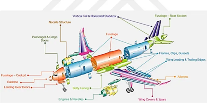
However, contrary to contemplation, footprints of this innovative technology relies on ancient times. At that time, natural adhesives derived from animals and plants were often used for bonding. Adhesive obtaining methods have also developed and diversified by the evolution of humankind. With the advent of synthetic adhesives in 1900s, interest in bonding technology has increased rapidly. In those days, adhesives were used to bond simple materials, but today more than 50% parts of Boeing 787 and the Airbus A350 aircraft are fabricated by various adhesive techniques (Cruz et al.). Accordingly, the goal of the literature review is to provide general insight into earlier work in the area of adhesively bonded joints, electrospinning, and reinforcement of electrospun polymers, and analysis of fracture behavior of adhesively bonded joints under different loads. These topics have been particularly taken into consideration in this study. A detailed literature review has been conducted and studies in the area have been reviewed.
2.1 Adhesively Bonded Joints
Baldan (2004) looked over the theoretical considerations and extensive practical tests on the adhesive bonding for metallic and non-metallic structures in the literature. He investigated the latest developments in this area of existing adhesives, emphasized effects of surface treatment, wettability, and surface energy in the adhesive joints, and highlighted the durability and performance of bonded joints under harsh environmental conditions. He reached the conclusion that the most appropriate technique for metallic and non-metallic structures was the adhesive bonding, where strength, stiffness, and fatigue life must be maximized at a
minimum weight. He also pointed that surface treatment and wettability were the critical factors to achieve a satisfactory bonded joints.
da Silva et al. (2009a) made detailed literature review on single and double-lap joints and discussed their applicability. They also examined all of the existing analytical models and helped the designers to select the right model for their application. In their subsequent works, da Silva et al. (2009b) focused on in particular the effects of surface pretreatment, joint design, adhesive properties, and environmental factors on the adhesively bonded joints of fiber-reinforced plastic (FRP) composite structures. They employed both analytical and numerical approaches to estimate failure in adhesively bonded joints and tried to determined accurate strength of the bonded structures.
After Banea and da Silva paper entitled “Adhesively bonded joints in composite materials: an overview” issued in 2009, many scientists and scholars have been worked on the performance of adhesively bonded composite joints by considering different parameters. Such as adhesive, adherent, environmental conditions, and analytical/numerical methods. Budhe et al. (2017) updated study of Banea and da Silva in 2009 by reviewing works in the literature from 2009 to 2016. In their paper published in 2017, they point out that although many deficiencies in the past have been overcome by developing new tecniques, there are still areas that need to be investigated.
Marques et al. (2015) worked on adhesive and adhesive bonding operating below and above the glass transition temperature (Tg). They investigated properties of different types of adhesive shrinkage, expansion, and viscoelasticity at low and high temperature. In their study, it was concluded that shrinkage generally would not be a problematic issue for the failure of adhesive joints, compared to thermal expansion. For the multi-material structures having differential thermal expansion especially used in aerospace industry, selection of adhesive/adherent and joint geometry were the most critical factors to reduce or evade joint’s early failure.
Katnam et al. (2013) reviewed damage assessment of bonded joints in aerospace industry. It was stated that the airworthiness of an aircraft depended on structural integrity, efficiency, and safety. In order to ensure these factors, some non-destructive tests such as ultrasonic techniques, thermography, and stereography were done for damage assessment. After damage detection, they proposed to follow a path, starting with removal of damaged composite including surface treatment, patch fabrication, analysis of patch strength and assessing patch integrity.
Banea et al. (2014) focused on the subject of smart adhesive joints for requirements of industry such as recycle, heal, or self-heal of bonded structures. They have reviewed the concepts and recent developments on self-healing methods and thermally expandable particles. Contrary to conventional repair methods, smart materials helps to avoid crack propagation. The concept of self-healing method depends on the principle that the crack propagation is evaded by the polymerization of the monomers previously stored in the bulk material. In this method, microcapsules or hollow glass fibers can be used. One of the main limitations of these systems is the depletion of the healing agent in the event of a microcapsule or hollow fiber breakage. In order to avoid this problem, microvascular network self-healing system is proposed by Toohey et al. (2007). Thermally expandable particles are used for recycling purposes. This method is based on the concept that heating the thermally expandable particles at a certain temperature leads to an easy separation of the bonded materials (Nishiyama et al., 2003).
Abdel Wahab (2012) paid a particular attention on fatigue and other hot topics related to fatigue in adhesively bonded joints in his paper. He revised about 222 cited articles issued from 1975 to 2011 and shed light on future work. He concluded that for achieving a good fatigue strength some parameters such as geometric/material parameters, surface treatment loading/ curing conditions should be optimized. It was also pointed out that topics such as fatigue durability, variable fatigue amplitude and fatigue in hybrid adhesive joints gained popularity among researchers, while impact/thermal fatigue did not attracted many researchers.
According to Mancusi and Ascione (2013), the performance of the adhesive bonding were linked to two parameters such as the failure load and optimal bonding length. They proposed two predictive formulae for these parameters, which having accounted for the cohesive parameters of the interface as well as the mechanical properties of the composite laminate. The validity of predictive formulae was compared with works of Mazzotti et al. (2008) and Carrara et al. (2011).
Pantelakis and Tserpes (2014) argued the bottlenecks and some recent advances of adhesive bonding technology in composite aircraft structures. They worked on the challenges such as environmental ageing (temperature, humidity, radiation, etc.) and pre/after-bond contamination that effecting the aircrafts structures during their service life. They defined all these factors as parameters that affecting durability of bonded joints. They observed that thermal ageing, long-lasting humidity exposure, and pre/after-bond contamination significantly degraded the performance of the joints.
Lopez-Cruz et al. (2017) tried to evaluate the effects of hybrid (bolted/bonded) composite joint behaviors in aircraft structures, which was started with HART-SMITH (1985) and elaborated by Stewart and Stewart (1997) and reviewed recently by Bodjona and Lessard (2016). They compared bolted/bonded joints with bolted joints and then with bonded joints respectively. It was concluded that the strength of bolted/bonded joints was 43.2% higher than bolted joints with adhesive FM300-2M and 66.17% higher than bolted joints with adhesive EA9361. It was also observed that the strength of bolted/bonded joints was 47.4% higher than bonded joints with adhesive FM300-2M.
2.2 Electrospinning and Reinforcement of Electrospun Nylon with Graphene
Palazzetti et al. (2012) investigated the influence of electrospun nylon 6.6 nanofibrous mat on the fracture mechanics of virgin and nano-modified laminates subjected to Mode I and the Mode II loadings. In both tests (DCB and ENF), it was observed that composite delamination strength and damage tolerance were upgraded with the help of electrospun nylon 6.6 nanofibrous mat.
Agarwal et al. (2013) emphasized importance of electrospinning technique for the modern life requirements. They investigated the preparation schemes, analyzed properties of the nanofibers in terms of electrospinning parameters, and evaluated the potential applications. They stated that electrospinning would be a pioneer especially in the field of life science (tissue engineering, drug delivery, wound healing, etc.), magnetic, optical, sensoric and micrometer-sized electronic devices.
Persano et al. (2013) explored technological approaches for upscaling of industrial electrospinning by reviewing literature between 2001 and 2011 and industrial capability. They focused on recent spinning and production technologies from laboratories to industry. It was concluded that the increasing demand in electrospinning raised interest in this area and made electrospinning apparatus more diverse and shophosticatic.
Huang and McCutcheon (2014) fabricated a flat-sheet polyamide membrane tailored for Engineered Osmosis (EO). It was supported by electrospun nylon 6.6 nanofibers. In the paper, it was stated that the membranes designed for EO had some properties such as excellent permeance and selectivity, highly porous, hydrophilic, and good chemical/thermal stability. In order to determine these properties, they conducted reverse osmosis and osmotic flux tests. They found that resulted membrane supported by hydrophilic electrospun nylon 6.6 nanofiber had a remarkably higher water flux than the cellulose acetate membrane.
Zhang and Yu (2014) put a special importance to the fabrication and applications of electrospinning with nanoparticles (NPs) and reviewed recent advances and future prospects. They focused on two main production strategies. One was preparing the NPs–electrospun fibers during electrospinning, and the other was preparing the NPs–electrospun fibers after electrospinning. Although the both methods were facile, cost effective, and flexible methods, they had several drawbacks. However, authors stressed that manufacturing NPs with fibers by electrospinning technique would present a new area for production of multifunctional materials in the future. They would be used in place of supercapacitors, batteries, and dye-sensitized solar cells owing to their large accessible surface area and relatively high electrical conductivity.
Hu et al. (2014) investigated the potential application of electrospinning in drug delivery. Its high loading capacity/encapsulation efficiency, ease of operation, and cost-effectiveness made this technology pioneer in drug delivery application. Compared to the others. Natural polymers (polysaccharides, proteins, and DNA etc.), synthetic polymers (polylactic acid-PLA, polyε-caprolactone-PCL, polyethylene oxide, and copolymers etc.), and hybrid polymers (blend of natural and synthetic) have been used to obtain electrospun fibers. They defined process parameters, morphologies, setups, and application of these electrospun fibers and discussed challenges such as fabrication of electrospun fibers in desired properties and in industrial scale, lack of in vivo studies compared with in vitro works, and sterilization problems met during reapplication.
Eatemadi et al. (2016) worked on electrospun nanofibers and their various applications in biotechnology. They focus on tissue engineering, delivery, and cancer therapy. The nanofiber scaffolds produced by electrospinning were used for tissue engineering, organ regeneration, and delivery of nucleic acids. Electrospun nanofibers were employed as wound dressings to protect a wound against external effects.
Albañil-Sanchez et al. (2013) synthesized graphite by direct oxidation of graphite powder, and then investigated morphology and microstructure of electrospun nylon/graphene nanocomposites by microscopy and X-ray diffraction. Pant et al. (2013) produced reusable and photocatalytically active titanium dioxide-reduced graphene oxide/nylon-6 (P25-RGO/nylon-6) filter membrane using electrospinning and hydrothermal treatment. Before manufacturing a desired electrospun spider-wave-like nanofibrous mats, they characterized neat nylon-6, GO/nylon-6, RGO/nylon-6, and P25-RGO/nylon-6 mats and evaluated their photo degradation and filtration efficiency. The order of water flux is observed P25-RGO/nylon-6>GO/nylon-6>nylon-6 respectively. It was concluded that P25-RGO/nylon-6 nanocomposite mat had a
good filter efficiency. Menchaca-Campos et al. (2013); Menchaca et al. (2014) made use of electrospun nylon 6-6/graphene oxide composite film for anticorrosion coating. The coating electrochemical resistance were assessed and results were compared to the silica or nylon samples.
Navarro-Pardo et al. (2016) reviewed electrospun polyamide nanocomposites incorporated with CNTs and graphene. They focused on the polyamide and its incorporation with fillers, and then discussed electrical, optical, crystallinity, and mechanical properties of CNT/graphene based polyamide electrospun nanocomposites. In the paper, it was highlighted the selection of a suitable solvent for the dispersion of carbon nanomaterials, the challenges in the alignment of nanomaterials. They reached the result that polyamide nanofibers reinforced with CNT/graphene could be used in many applications such as electronic devices, drug delivery systems, sensors, wearable electronic devices, or filtration. Wahab et al. (2016) studied on production of electrospun nanofibers incorporated with graphene oxide, its properties, and applications. They reviewed previous works and made suggestions to shed light on future studies.
2.3 Fracture Behavior of the Adhesively Bonded Joints
The single lap joints is the most common way for producing in-situ shear strength data of an adhesively bonded joint. Volkersen (1938) pioneered the determination of stress distribution in lap joints with his shear lag analysis. Goland and Reissner (1944) took Volkersen analysis a little further by taking bending moment and joint rotation into account in their calculation. In 1973, Hart-Smith proposed a model considering elasto-plastic behavior in both adhesive and adherents (Hart-Smith, 1973). Adams and Peppiatt (1974) worked on the effects of Poisson’s ratio that affecting shear stresses along the width and the length of an adhesively bonded joints. Bigwood and Crocombe (1989) investigated the non-linear analysis of both adhesive and adherent under several loadings. Delale and Erdogan (1981) tried to calculate stress distribution in the adhesive layer by Laplace transform technique. In their adhesively bonded lap joint tests, it was assumed that the adherents behaved elastic while the adhesive acted linearly viscoelastic. In recent years, numerous works have been done on the single lap joints, taking into account very different parameters. Elhannani et al. (2016) focused on optimization design of adhesively bonded single-lap joint. They made geometrical modifications on the adhesive and adherents edge to have a decline in peel and shear stresses. Soltannia and Taheri (2015) made comparison between the nano-reinforced adhesive and those
of the neat thermoset resin and a toughened acrylic–epoxy adhesive. It was found that the nano-reinforced adhesive had a positive effect on mechanical behavior of adhesively bonded single-lap joints subjected to different loadings.
Gültekin et al. (2015) made experimental and numerical studies on mechanical properties of single lap joint configurations under tensile loading. They used two different types of configurations; while one had identical upper and lower adherent thicknesses, the other's adherents had not. It was observed that while the increase in adherent thickness did not make a significant contribution to the strength of the joint that changed the stress concentrations at the edges of the overlap regions.
Fernandes et al. (2015) carried out experimental works on the performance of Araldite® AV138 (brittle), Araldite® 2015 (moderate), and SikaForce® 7888 (ductile). They employed single lap joints configurations with varying values of overlap length ranging from 1, 5 mm to 50 mm. They compared the experimental results with numerical approximations. Both cohesive zone models (CZM) and the extended finite element method (XFEM) was used as a numerical analysis. They found that while CZM was consistent with experimental results, XFEM was not the most appropriate method for mixed-mode damage growth.
Chaves et al. (2014) made an investigation on fracture mechanics tests in adhesively bonded joints. They explained the basic methods to characterize the mechanical and structural performance of adhesive joints by using analytical and numerical techniques. Mode-I fracture tests [the double cantilever beam (DCB) and the tapered double cantilever beam (TDCB)], Mode-II fracture tests [end-notched flexure (ENF), end-loaded split (ELS), and the four-point end-notched flexure (4ENF)], and Mixed-Mode (I/II) fracture tests were studied to understand their advantages and disadvantages.
Yang et al. (2001) used a pure mode-II cohesive-zone model to simulate the elastic– plastic mode-II fracture of adhesive joints. They wanted to characterize fracture of adhesively bonded end notched flexure deforming plastically. They gathered the fracture parameters from
a particular ENF specimen geometry. These experimental results were verified by numerical
techniques, and then used for fracture prediction of other ENF specimens with different geometries. They observed that numerical predictions were in perfect harmony with the experimental results.
Markatos et al. (2014) worked on the effects of pre-bond contamination of adhesively bonded composite joints. They tested specimens, which was contamined with silicone-based release agent and moisture before bonding at varying concentrations. For silicone-based release
agent, when the contamination level increase degradation of fracture toughness was significantly big, compared to the untreated specimens. For moisture effect, it was concluded that increase in water-uptake values resulted in a 26% decrease in fracture toughness.
Floros et al. (2015) characterized the fracture toughness of composite bonded joints under mode-I, mode-II, and mixed-mode I + II loadings. The experimental results were also checked by the cohesive zone modeling method. The EA 9695 film adhesive and the mixed EA 9395-EA 9396 paste adhesive were used for bonding the composite adherents. It was observed that fracture toughness of the joints with paste adhesive was smaller than the joints with film adhesive. Furthermore, it was concluded that while the numerical model in model-I gives results that were consistent with the experimental results, the results obtained in II and model-III could not exhibit the desired accuracy due to the complex fracture behavior.
2.4 Adhesives
2.4.1 Adhesive and Adhesive Bonding
Although various definitions depending on requirements of users have emerged, it is very hard to find entirely satisfactory explanation for all parties. Nevertheless, the following definition still has been most widely accepted by a large majority so far.
Adhesion, which means stick to, is used to describe a state where at least two surfaces are held together and resist their separation.
Adhesives are used to join similar or dissimilar materials like metals, plastics, ceramics, and any other kinds of combination. The materials attached to one and another by an adhesive is called adherent or substrate, a word first used by Bruyne in 1939 (Kinloch, 2012).
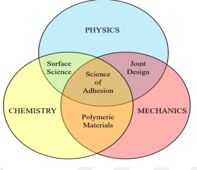
According to Petrie (2006) the science of adhesion in the center of primary sciences of physics, mechanics, and chemistry and any person interested in adhesives or its derivatives must be familiar with all of the relevant technologies as shown in Figure 2.1.
Figure 2.1 The science of adhesion requires the adaptation of multiple disciplines; (Petrie, 2006) Adhesives have several common characteristic as follows:
To form surface attachment through adhesion.
To improve strength and improve bonding carrying capacity.
To transfer and distribute load among the components in an assembly.
What is expected from an adhesive? (Comyn, 1997): Wet the surfaces,
Adhere to the adherents,
Harden after it has been applied, Remain stable.
In order to achieve these goals, adhesive selection process is very crucial. According to Petrie (2006), many different inputs such as application and bonding methods, service environment, cost etc. directly influence this choice. However, it should not be forgotten that it is impossible to find a perfect adhesive that meets all expectations. Therefore, user to make the appropriate selection must answer following several basic questions (Ebnesajjad and Landrock, 2014):
To what type of adherent be attached?
In what temperature range be expected to perform? What type of chemicals meets?
Be functional after installation?
After selection of a correct adhesive, basic requirements of a good bonding must be determined as (Petrie, 2000; Ebnesajjad, 2010);
Good joint design (selection of proper design),
Surface preparation (Cleaning and abrasion of the surface),
Wetting (Applying and spreading proper amount of selected adhesive),
Proper adhesive bonding process (Assembly of adherents, clamping parts in a fixture at a controlled pressure and curing).
The common use of the modern adhesive bonding is triggered by the development of the aircraft and aerospace industries. After that time, adhesive bonding has gained popularity in a great variety of industries ranging from undemanding sticky tapes to complex microelectronics packaging for their accessibility, convenience, and high efficiency. With the advent of new applications of bonding, dentistry and surgery have also been showed up in this new area. Compared to traditional methods of joining, adhesive bonding has some significant dominance, such as high strength/weight ratios, more design flexibility, relatively cost effectiveness, and so on. In order to maximize the joint efficiency, stress distribution must be taken into consideration by the designer. For them, type and value of load, mechanical properties of adhesive (shear modulus), geometry of the bond area (adhesive thickness), and physical properties of adherent (Young’s modulus) are the key parameters (Mittal, 2012; Wahab, 2015).
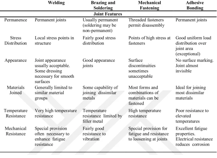
While in mechanical, joining the strength of the structure is directly related with the strength of the fasteners, in adhesively joined structures it is almost opposite. Because adhesives have ability to transmit stresses from one adherent to another much more uniformly than mechanical fastenings. Table 2-1 summarizes the comparison of these joining methods (Petrie, 2000).
Table 2-1 General Comparison of Joining Process (Petrie, 2000)
Welding Brazing and
Soldering Mechanical Fastening Adhesive Bonding Joint Features
Permanence Permanent joints Usually permanent (soldering may be non-permanent) Threaded fasteners permit disassembly Permanent joints Stress Distribution
Local stress points in structure
Fairly good stress distribution
Points of high stress at fasteners
Good uniform load distribution over joint area (exceptional) Appearance Joint appearance
usually acceptable. Some dressing necessary for smooth surfaces Good appearance joints Surface discontinuities sometimes unacceptable No surface marking. Joint almost invisible Materials Joined Generally limited to similar material groups Some capability of joining dissimilar metals
Most forms and combinations of materials can be fastened
Ideal for joining most dissimilar materials Temperature
Resistance
Very high temperature resistance Temperature resistance limited by filler metal High temperature resistance Poor resistance to elevated temperatures Mechanical Resistance Special provision often necessary to enhance fatigue resistance Fairly good resistance to vibration
Special provision for fatigue and resistance to loosening at joints
Excellent fatigue properties.
Electrical resistance reduces corrosion
2.4.2 Advantages and Disadvantages of Adhesive Bonding
Adhesive bonding has a number of superiorities over mechanical fastening but also it has some drawbacks or limitations (Peckham, 1992; Adams et al., 1997; Petrie, 2000).
Advantages; Adhesives, Applied;
Any kind of materials (at least two/more, thin/thick, similar/dissimilar and heat sensitive),
More easily and/or quickly than mechanical fastening, Resist;
Corrosion, Fatigue Cyclic loads,
Seals against gases, liquids, Provide;
Uniform stress distribution and larger stress bearing area (Figure 2.2), Electric insulation, thermal stability.
Vibration damping and shock absorption (Figure 2.3), Design flexibility and esthetic,
Strength/weight ratio, Smooth contours.
Figure 2.2 The stress distribution for bolts, welds and adhesives (Anonymous, 2016)
Figure 2.3 Vibration damping (da Silva, 2013) Disadvantages; Adhesives,
Need;
No specific adhesive for particular job, Long cure times,
Careful surface preparation, Clean and plain surfaces, Rigid process control,
Jigs and fixtures for clamping, Skillful and knowledgeable person. Limited;
At elevated temperatures (Figure 2.4), Shear and peeling strength,
Repairing of complex adhesives,
Against harsh environmental conditions, Non-destructive quality control methods.
Figure 2.4 Vulnerability to temperature (da Silva, 2013)
2.4.3 Types of Adhesively Bonded Joint Designs
During the design phase, the designer, such as environmental conditions, peeling/cleavage stresses, safety margins, temperature range, service time, cost and surface preparation, must consider many factors and so on. The most basic design algorithm for the bonded joints is presented in Figure 2.5 (Mittal, 2012).
Figure 2.5 Basic design cycle (Mittal, 2012)
Among all these factors, uniform stress distribution and reducing the peeling/cleavage stress are the most critical ones. Analytical and numerical methods are used to analyze the joint strength. The most common and the most investigated joint is single-lap joint (da Silva et al., 2011).
In order to have a good lap joint design; Adhesive should;
Have a low modules and ductile behavior, Be loaded in shear whenever possible, Have a uniform and thin adhesive layer. Adherent should;
Have higher modulus,
Have minimal peeling/cleavage stresses. Have a large bonding/overlapping area, Be similar.
The following Figure 2.6 shows the most widely employed types of joint designs (Noorman; Adams et al., 1997; da Silva et al., 2011);
Figure 2.6 Some common adhesive joints (Noorman)
2.4.4 Types of Stress
All adhesive joints are exposed to a wide variety of loads throughout the life cycle. Under these forces, they are expected to maintain their status. There are four basic types of loading stress in adhesive joints: These are as illustrated in Figure 2.7 (Comyn, 1997; Petrie, 2006);
Tensile, Shear, Cleavage, Peel.
Figure 2.7 Types of loading stress (Comyn, 1997)
2.4.4.1 Tensile Stress
Tensile stress arises from when the two bonded adherents are pulled apart from each other, vertical to bonding line. It is the most severe form of loading, because the strength of joint depends on the tensile strength of the adhesive. If the joint design is not properly set, a small crack first arises at the most stressed area, then propagates rapidly and leads to failure of the joint. Uniform distribution of tensile loading is very critical for service life of joints. In practice, rigidity of adherents, design of joint and bond thickness are critical factors that need to be checked for equal load distribution.
If the two adherents are forced to contact each other, compressive stress develops. In this type of loading, unless the adhesive fails cohesively, joint protects the existing structure.
2.4.4.2 Shear Stress
Shear stress arises from when the two bonded adherents are forced to slide each other, parallel to bonding line. The bond strength depends on joint geometry and physical properties of adhesive/adherent. Lap shear joint is the most used bonding techniques in adhesive bonding. In this theory, the shear modulus of the adhesive and tensile modulus of the adherent is different from each other; this difference causes shear stress. This shear stress goes up at the overlap ends.
2.4.4.3 Peel Stress
Peel stress occurs when a flexible adherent are forced to separate from the other rigid or flexible part. It is used extensively to evaluate the bonding strength of adhesive and flexible adherents such as rubber, films, tape, labels and so on. Peel tests are usually performed at a constant rate and various angles.
2.4.4.4 Cleavage Stress
Cleavage is defined as the stress occurring when forces are applied to the one edge of joint; the other edge provides little to the total strength of joint. Most of the stress gathered on force loaded edge. Compared to the tensile and shear stresses, cleavage and peel stresses are unattractive for adhesives.
2.4.5 Adhesive Bonding Theories
Adhesion simply occurs when two adherents come into contact by and adhesive. Thus, adhesion is a surface phenomenon need to be investigated. This event can be explained by cohesion and adhesion forces arise at the interface by weak molecular interactions or strong chemical bonds or both as shown in Figure 2.8.
Figure 2.8 Bonding theory (Anonymous, 2017)
The interaction of molecules and atoms causes an attraction between adhesive and adherent (Figure 2.9). This attraction consists of primary bonding, hydrogen bonding, and secondary bonding. In order to understand adhesion mechanism, we should know types of forces functioning at the interface (da Silva et al., 2011). These forces are:
van der Waals forces (physical adsorption), hydrogen bonding (strong polar attraction),
Figure 2.9 Components of a typical adhesive joint
It is very hard to find a general model that covers either exact nature of these interactions nor their direct additive effects to the adhesion. Over years, researchers have tried to find an answer to this phenomenon.
In order to explain how adhesion works, theoretical and practical studies ranging from very simple to very complex, researchers have been broadly studied and at the end of these studies, the new models have been presented. Despite all these proposed models, mechanism of adhesive bonding has not been fully explained so far. Each theory has its own path and applicability. Therefore, there is currently no unified theory to meet all needs. It is required the use and mixture of different theories to explain all cases. Because the theory, for instance, being sufficient to explain bonding of a rough timber to some extent may be insufficient for bonding of helicopter rotor blades.
Presently there are several traditional theories trying to clarify the phenomenon of adhesion (Pizzi and Mittal, 2003). These theories are based on concepts of atomic, molecular, microscopic, and macroscopic levels. However, each day new theories are being added to the previous list as shown at Table 2-2.
Table 2-2 Theories of Adhesion (Ebnesajjad, 2010)
Traditional Recent Scale of Action Mechanical interlocking Mechanical interlocking Microscopic
Electrostatic Electrostatic Microscopic Diffusion Diffusion Molecular Absorption/Surface reaction Wettability Molecular Chemical bonding Atomic
Acid-base Weak boundary layer
Molecular Molecular
2.4.5.1 Mechanical Interlocking Theory
In this theory, adhesive first flows on the adherent and penetrates into roughness of surface, then removes the trapped air from the surface of adherent and solidifies to produce an adhesive bond by mechanical interlocking as shown in Figure 2.10 (Ebnesajjad, 2010).
Figure 2.10 Mechanical interlocking theory (Anonymous, 2016)
The idea of mechanical interlocking theory goes back to bonding works of McBain and Hopkins in 1925 (McBain and Hopkins, 1925; Peckham, 1992; Petrie, 2000). After them, the study of Borroff and Wake (1950) on measurement of adhesion between rubber and textile fabrics contributed to the explanation of this method. They proved that penetration of the protruding fibers into rubber enhances the adhesive joint.
According to the Kinloch (1987) the major shortcomings of this theory is its inability to explain the good adhesion among some smooth surfaces. In order to obtain a good adhesion on smooth and polished surfaces, this method alone would be insufficient. Because, it is still controversial to find out whether increase of adhesion strength originated from mechanical interlocking or secondary bonding (surface wetting).
Thus, it was suggested by Gent and Schultz (1972), Wake (1976) to take into consideration thermodynamic interfacial interactions along with mechanical effects for estimating the joint strength (Thomas, 2016). In addition to the mechanical keying, the surface roughness and/or properties of adhesives are considered as important factors in obtaining the improved adhesion as well (Pizzi and Mittal, 2003).
Optimum joint strength = (constant)
x (mechanical keying component) x (interfacial interactions component)
2.4.5.2 Electrostatic Theory
The electrostatic theory, made known by Deryagin et al. in the 1950s, is a force of attraction between a charged surface and a conducted adherent (Budzik, 2010). Different electrical structure of adhesive/adherent creates an electrical double layer at interface, which causes adhesion (Kinloch, 1987). In this theory, use of materials having high electron-transferring capacity is very crucial to increase the strength of bonding as shown in Figure 2.11 (Lee, 2013). In this theory, the adhesive-adherent junction acts as a capacitor and during separation of system potential difference increases until discharge occurs. The main critique of this theory is that electrostatic forces is not a cause of a good adhesion but an effect. Because, during failure processes electrical double layer occurred at interface are the consequence rather than the cause of high bond strength (Sawalha, 2016).
Figure 2.11 Electrostatic theory (Anonymous, 2016)
2.4.5.3 Diffusion Theory
The diffusion theory is attributed to the studies of Voyutski and his colleagues in the mid-years of the 20th century (Voyutskii, 1963). In this theory, above the Glass Transition Temperature (Tg), macromolecular chains first begin to move, and then diffuse into the adherent to make a good bonding. This theory also requires the molecules soluble enough and sufficiently mobile across the interface. After diffusion, the original boundary between two surfaces vanishes, thus no stress concentration occurs in all structure. Contact time, temperature, polymer type, and viscosity have great effects on the adhesion strength as illustrated in Figure 2.12 (Kinloch, 2012).
Figure 2.12 Diffusion theory (Anonymous, 2016)
2.4.5.4 Absorption Theory
Comparted to other theories, the absorption theory is the most commonly studied and recognized theory of adhesion. It has gain great acceleration from the works of Zisman and his coworkers (Adams et al., 1997). In this theory, in order to have a good adhesion, interatomic and intermolecular forces must be established at the interface. These forces can be classified as secondary bonds such as ionic and co-valent bonds, hydrogen bonds, dipole interactions and van der Waals forces are among these forces. Contact angle, wet ability, and surface tension constitute the three most important pillars of this theory as shown in Figure 2.13 (Adams, 2005). Liquid crystal polymer and silicone adhesives, most bituminous adhesives are some of the examples of this theory. The difficulty of measuring the properties is the most challenging issue for implementing this method (Li et al., 2012).
Figure 2.13 Absorption theory (Anonymous, 2016)
2.4.5.5 The Weak Boundary Layer Theory
Bikerman (2013) first put this theory forward in 1967. According to him, weakness of the material can be classified under seven titles such as:
1. Air,
2. The adhesive, 3. The adherent, 4. Air and the adhesive, 5. Air and the adherent,
6. The adhesive and the adherent-adhesive, 7. All three.
Air, at the beginning of classification, is the most common type of weak boundary failure. Weak boundary layer can arise from the environment, the adhesive, and the adherent. Some contaminants in adhesive, adherent, or impurity coming from environment may form a weak zone at the interface. In Figure 2.14 weak boundary layers are shown for both metal and plastic surfaces. In order to prevent formation of this weak zone, the use of surface treatment methods is very important (Schneberger, 1983).
Figure 2.14 Weak boundary layer theory
2.4.5.6 Chemical Bonding Theory
The chemical bonding is a way of attraction between adherent and adhesive by forming surface chemical reactions. During these chemical reactions, primer chemical bonds such as ionic and covalent bonds and Lewis acid-base bonds are formed across the interface as shown in Table 2-3. Compared to secondary force interactions such as van der Walls and hydrogen bonds, the primary chemical bonds have stronger bonding energies. In this theory as illustrated in Figure 2.15, the chemical composition of the interface is decisive to determine the strength of adhesive bond (Hartshorn, 2012).
Table 2-3 Bond energy of some of the common interactions (Budzik, 2010)
Type of interaction Example E (kJ/mol) Range
Covalent C-C C-O Si-O 368 377 368 0.1-0.3 Ionic Na+ Cl- Al3+O 2-Ti4+O2- 503 4290 5340 Hydrogen bond -OH···O=C
-OH···OH -OH···N F···HF 30 32 35 165 ≤0.2 Lewis acid-base BF3+C2H5OC2H5 C6H5OH+NH3 SO2+ C6H5 64 33 4.2 Van der Waals forces Dipole-dipole
Dipol-induced dipole Dispersion ≤2 0.05 ≤2 100 (retarded)
Figure 2.15 Chemical boundry theory (Anonymous, 2016)
2.4.5.7 Wetting Theory
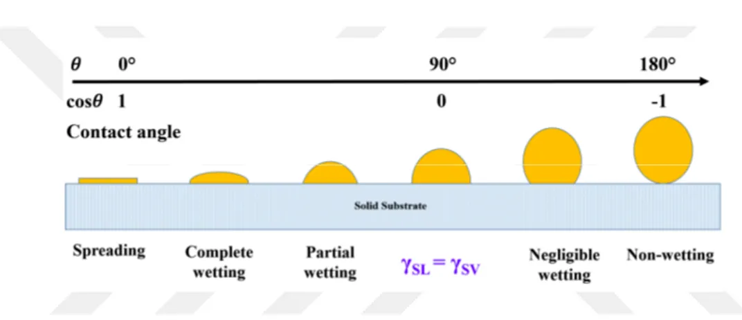
The theory of wetting is explained by the relation of three phases, namely liquid, surface and vapor. When a drop of liquid is located on the surface of a adherent, it tries to go into steady state somewhere between spreading and wetting. The state between spreading and non-wetting of a liquid is defined by contact angle. When the contact angle goes from 0° to 180° degrees, the degree of wetting moves from spreading to non-wetting simultaneously as shown in Figure 2.16.
When the contact angle is less than 90°, wetting occurs on the surface and it is called a hydrophilic surface. However, if the contact angle is larger than 90°, not enough wetting can be observed and this situation is called a hydrophobic surface. This angle is called super
hydrophilic ( < 5°) or super hydrophobic ( > 150°) for the surface as these values approach the extreme values in both directions (Wahab, 2015).
When the literature survey is made, we can see that the use of the four main methods has been highlighted in determining the contact angle. The first three of these methods perform calculations on a macroscopic angle while the fourth method calculates on a microscopic angle . These are as follows:
Direct geometric measurement,
Determination from measured capillary shapes of the system,
Measurement by a force balance and comparison with the surface tension, Calculation from intermolecular forces.
Figure 2.16 Wetting and contact angle (Njobuenwu et al., 2007)
This angle (Figure 2.17) is described as the angle between the tangent to the liquid surface and the liquid/solid surface at the point of liquid/solid contact. The relation between surface tension and the wettability is calculated by the help of Young’s equation as follows. (Good, 1993; Yuan and Lee, 2013).
= + cos (2.1)
where solid, liquid, and vapor symbolizes as the subscripts S, L, and V and γSL, γSV, and γLV
represents respectively the interfacial energies of the solid-liquid, solid-vapor, and liquid-vapor interfaces, represents the contact angle of the liquid. Young’s equation is only valid for ideal situation and the solid-liquid interactions are essentially neglected. These interactions between solid and liquid is the crucial parameter for the strength of the bonded joints. The wetting produces a positive effect on the work of adhesion by forming intimate contact between the adhesive and the adherent (Wahab, 2015). In order to have good wetting, the surface free energy
(surface tension γLV) of the adhesive must be either smaller or at least equal the surface tension
(γS) of the adherent, or < .
Figure 2.17 Wetting theory (Njobuenwu et al., 2007)
After studies of Thomas Young in 1805, the most serious contribution was provided by the work of Dupr´e in 1869. He tried to explain the wetting phenomenon with the work necessary to split two different phases. According to his concept, the surface energy (γ) is intimately related to adhesion phenomenon. This phenomenon is defined as a reversible energy to separate interface from the equilibrium state or vice versa. The work of adhesion (WA) is
included in the game when one liquid or solid surface encounters another liquid or solid surface. Similarly, the work of cohesion (WC) can be a player in the game when two similar surfaces
adhere together to obtain one uniform object. This phenomenon is determined by Dupre’s following equation:
= + − = (1 + cos ) (2.2)
= 2 (2.3)
According to the Dupre’s equation, if the contact angle is small, good adhesion occurs due to high surface wettability otherwise, the opposite happens. After Dupr´e, numerous studies and theories were proposed to clarify the wetting phenomenon (Hejda et al., 2010). Fox and Zisman (1950) made experiments to estimate a direct measurement of the wettability of a solid. Girifalco and Good (1957) worked on a method for better estimation of surface and interfacial energies between a solid and a liquid. Then, based on the works of Fox and Zissman in 1950,
Owens and Wendt (1969) developed the geometric mean method for determining the surface energy of solids.
2.4.6 Adhesive Bonding Failures
Adhesive bonding failures can occur in many different ways. In order to understand the phenomena of these failures, it is first essential to recognize how adhesive bonds function. As Kinloch (1987) stated that adhesives form chemical bonds at the interface between adhesive and adherent during the adhesive is cured. These chemical bonds effect types of failure. An adhesive bonded structure may fail in their basic ways as illustrated in Figure 2.18. These are:
Cohesive failure: It takes place where cohesive strength < interfacial strength. Failure of the joint at the adhesive/adherent interface.
Reasons;
Design deficiency (inadequate overlap length and poor joint design), Excessive porosity,
High peel and thermal stress.
Adhesive failure: It takes place where cohesive strength > interfacial strength. It is also named as disbonding.
Failure of a bonded joint between the adhesive and the adherent. Reasons;
Contamination during manufacture, Use of aged adhesive,
Poor processing (inadequate temperature control, surface preparation). Mixed failure
Structural failure: It takes place anywhere in the adherent of the bonded joint when the adhesive is stronger than the adherent in the joint.
Failure of adherent instead of adhesive. Reasons;
Fault in ply matrices, Improper curing of plies.