BUILDINGS BY THE USE OF FRP AND STEEL FUSE ELEMENTS
Conference Paper · May 2010CITATION
1
READS
103
4 authors:
Some of the authors of this publication are also working on these related projects:
I am a visiting scholar at the Wichita State UniversityView project
Demonstration of Efficiency of Seismic Retrofit with CFRPs through Full-Scale Site Testing of Sub-Standard RC StructuresView project Ahmet Murat Türk
T.C. Istanbul Kultur University 17PUBLICATIONS 172CITATIONS
SEE PROFILE
Mustafa Cömert
RISE Engineering and Consultancy 40PUBLICATIONS 61CITATIONS SEE PROFILE Cumhur Cosgun Marshall University 20PUBLICATIONS 50CITATIONS SEE PROFILE
Mustafa Gökhan Kesti
University at Buffalo, The State University of New York 4PUBLICATIONS 5CITATIONS
INCREASING SEISMIC CAPACITY OF EXISTING REINFORCED CONCRETE BUILDINGS BY THE USE OF FRP AND STEEL FUSE ELEMENTS
A. Murat TURK, Dept. of Civil Engineering, Istanbul Kultur University, Turkey Mustafa COMERT, Dept. of Civil Engineering, Istanbul Kultur University, Turkey Cumhur COSGUN, Dept. of Civil Engineering, Istanbul Kultur University, Turkey M. Gokhan KESTI, Dept. of Civil Engineering, Istanbul Kultur University, Turkey ABSTRACT
Two of major problems for seismic rehabilitation of existing buildings are the necessity of evacuation of the occupants from the basis of the construction works and the limited time frame available for the actual construction site works. All of these problems often cause delays and cost overruns in the seismic rehabilitation projects. One possible way to eliminate these problems to a great extent is the use of FRP (fiber reinforced polymer) and steel fuse elements to improve seismic capacity. There is a huge stock of seismically deficient buildings that needs to be upgraded immediately according to the current Turkish Seismic Code (TSC 2007).
The main aim of the paper is the examination of the possibility of using FRP and steel fuse elements on existing frame elements for seismic upgrading of the school and hospital buildings in Turkey. To investigate the possibility and effectiveness of the use of the hybrid system, a comparative study was
performed. The comparison has made between typical framed RC building and the same building after retrofitting with FRP confinement and steel fuse elements around joints. By using nonlinear static (pushover) analysis, the performance levels of structural members were evaluated for both structures. This method seems as viable solution for the buildings considered in terms of safety and time.
INTRODUCTION
Throughout the history, earthquakes are the most important natural hazards in human life and it is still a major threat for mankind. The overwhelming majority of deaths and injuries in earthquakes occur because of the disintegration and collapse of buildings; and much of the economic loss and social disturbance caused by earthquakes is equally attributable to the failure of buildings and other man-made structures.
Turkey has had a long history of large earthquakes that often occur. Within the last ten years Turkey was hit by several moderate to large earthquakes causing life and property losses. They are; 1992 Erzincan, 1995 Dinar, 1998 Ceyhan, 1999 Kocaeli and Duzce earthquakes. Especially 1999 Kocaeli and Duzce earthquakes caused extensive damage through a very large region extending from Tekirdag to Eskisehir, cities mostly affected are Sakarya, Duzce, Yalova, Kocaeli, Bolu and Istanbul. The intensively damaged region follows an area of about 20 km wide (10 km to the north and south of the fault) along the fault rupture. The number of damaged buildings after the earthquakes amounted 23,400. About 16,400 of these were heavily damaged and collapsed buildings during the earthquakes which cover around 93,000 housing units and 15,000 small business units.
In Turkey, there are a huge number of existing seismically deficient buildings, especially made of reinforced concrete. A great majority of the residential and office buildings, which are normally low-rise to mid-rise reinforced concrete frames, have not been engineered well to resist major or even moderate earthquakes. Strengthening of existing reinforced concrete frames prior to earthquakes and repair of damaged ones after earthquakes are extensively used in practice. The vulnerability of the structure depends on the deficiencies in lateral stiffness, strength and overall ductility aimed at the design stage. The construction deficiencies also add up to the vulnerability. Strengthening or repair of individual structural members such as beams and columns is feasible if the number of the members, which require rehabilitation, is limited and if the overall drift requirements of the structural system are satisfied. If the above requirements can not be satisfied properly, strengthening of such frames by adding infills to selected bays of a structure appears to be a logical and economical solution to reduce the risk of damage. If these infill walls are constructed properly, infilled frames will behave like shear walls and will take almost the total lateral load and improve the lateral stiffness.
On the other hand, one of the major problems, in terms of seismic rehabilitation of existing buildings, is the necessity of evacuation of the occupants from the basis of the construction works. Many times it is very costly and burdensome to the users/owners of the building. Second problem usually is the limited time frame available for the actual construction site works. The last but not the least problem is what can be cited as the hidden problems, such as changes made to the building systems after the commissioning and not reflected in the as-built drawings. All these problems often cause delays and cost overruns in the seismic rehabilitation projects. The state schools and hospitals in Turkey mostly are in this category. A typical school building is shown in Figure 1 as shown below. Moreover, there is a huge
stock of these buildings that needs to be upgraded to the current Turkish Seismic Code1 (TSC 2007) which has similar requirements with IBC-20062 and Eurocode 83.
Figure 1 Typical Turkish State School Building (Reinforced Concrete Frame) Conventionally, seismic design of building structures which plays a vital role in earthquake protection is based on the concept of increasing the lateral load resistance capacity of the structures against earthquakes by employing, for example, the use of shear walls, braced frames, or moment-resistant frames. In other words, to avoid damage, axial load capacity and deformability of such vertical structural members may need to be enhanced to exhibit
satisfactory seismic performance. High strength fiber reinforced polymer (FRP) composite sheets can increase the axial strength and deformability of the members. Comparing with the other retrofitting techniques, FRP has many advantages such as lower density, higher tensile strength and modulus, durability and good construction workability. Because of these advantages, the use of FRP composites for retrofitting the structural systems has been increasing rapidly in recent years. In addition, the protection/upgrading of the beam-column joints against shear damage is needed. Because a typical older construction practice in such buildings shows that beam column joints practically do not have any shear reinforcement (no tie bars in the joint region). Placing a simple steel fuse elements around the joints (steel haunch elements) tied up to hinged plates which are connected to the beams and columns by eliminating damage to the joint and formation of a plastic hinge in the beam at the location of the beam-haunch connection far from joint region. This system is reported as with the results of increase in the global lateral strength, a stable hysteretic behavior and enhanced energy dissipation capacity4. In the same study, researchers showed that mounting a haunch type element is introduced at the beam to column joint region, the shear forces and moment diagrams of the beam-column assembly are significantly reduced. As it is well known, shear hinge mechanism in beam-column joints have critical effects on the global response of a framed building. A retrofit strategy consisting of introducing haunch type elements locally, close to the beam-column joints has been investigated numerically as a means to significantly enhance the seismic performance of the buildings while reducing the damage in exterior joints as well as preventing the soft storey mechanisms.
In this study, a typical school building is seismically upgraded by CFRP confinement and steel fuse (haunch) elements around joints. A comparative study was performed on a typical
RC building frame chosen. Mainly, three different configuration of this frame was analyzed, Case A: bare frame, Case B: frame members wrapped with CFRP, Case C: frame members wrapped with CFRP and steel bars hinged around the beam-column joints. The building structure considered here represents a low rise RC building. This building consists of a typical beam column RC frames with no shear walls, located in a highly seismic region of Turkey. Since the majority of buildings were constructed according to the TSC-19755 the building is designed according to this code, considering both gravity and seismic loads (Seismic Zone 1 with a design ground acceleration of 0.4g, soil class Z4 acc. to TSC-20071 Type D soil acc. to Eurocode 83). Material properties are assumed as 12 MPa for the concrete compressive strength and 220 MPa for the yield strength of both longitudinal and transverse reinforcements. A single layout is considered for transverse reinforcement in the potential plastic hinge regions, with 200 mm spacing representing the typical ranges in typical construction.
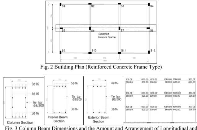
The 3-storey school building is 18 m by 10 m in plan (Fig. 2). Typical floor height is taken as 3.5 m which is a typical height for school buildings. The interior frame as shown in Figure 2 represents 2-D models of this building. The column and beam dimensions used in this study are typical frame element proportions in the existing building stock. Column dimensions and the amount and arrangement of longitudinal reinforcement are provided in Fig. 3. All beams are 300x600 mm and the amounts of top and bottom reinforcement are shown
Fig. 2 Building Plan (Reinforced Concrete Frame Type)
Fig. 3 Column Beam Dimensions and the Amount and Arrangement of Longitudinal and Transversal Reinforcements
PUSHOVER ANALYSIS
Analyses have been performed using SAP20006 which is a general purpose structural
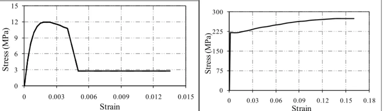
analysis program for static and dynamic analyses of structures. In this study, SAP2000 Nonlinear Version 12 has been used. A description of the modeling details is provided in the following. A two-dimensional model of the structure is created in SAP2000 to carry out nonlinear static analysis. Beam, column, steel haunch elements are modeled as nonlinear frame elements with lumped plasticity by defining plastic hinges at both ends of the beams and columns. The user defined flexural hinge properties were prepared by moment–curvature analysis of each structural element by using section analysis software7. Mander8 model for confined concrete and the typical steel stress–strain model with strain hardening for steel are implemented in moment–curvature analyses (Figure 4). Cracked section stiffness for RC
beams and columns were taken as 0.4EI according to TSC 20071.
0 3 6 9 12 15 0 0.003 0.006 0.009 0.012 0.015 St re ss (M Pa ) Strain 0 75 150 225 300 0 0.03 0.06 0.09 0.12 0.15 0.18 St re ss (M Pa ) Strain
Fig. 4 Unconfined Concrete Model C12 (fc=12 MPa) proposed by Mander5 and elastoplastic
steel model including strain hardening for S220 (fy=220 MPa)steel
For each column, moment–curvature analyses are carried out, considering section properties and constant axial loads on the elements. On the beams, axial forces were assumed to be zero while the axial load on the columns were assumed to be constant and equal to the load due to the dead loads plus 30% of the live loads. The input required for SAP2000 is the moment– rotation relationship instead of the moment–curvature relationship. Also, moment–rotation data have been reduced to a five point input that brings some simplifications. Plastic hinge length is used to obtain ultimate rotation values from the ultimate curvatures. For the user defined hinge properties, plastic hinge length is considered as 0.5H where H is the section depth. In existing reinforced concrete buildings, especially with low concrete strength and poor confinement, the shear failure of members should be taken into consideration. For this purpose, shear hinges are introduced for beams and columns. Because of the brittle failure of concrete in shear, no ductility is considered for this type of hinge. Shear hinge properties are defined such that, when the shear force in the member reaches its strength which is calculated according to TS-5009, the member fails immediately.
For the RC sections with CFRP wrapped, moment–curvature analyses are carried out again, considering section properties and constant axial loads on the elements and CFRP
mechanical properties with the assumption of full bond between concrete and CFRP. A
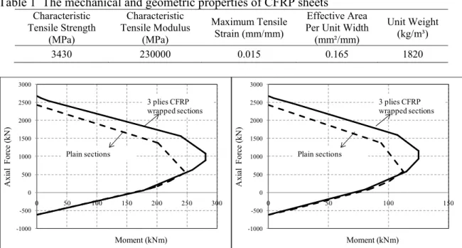
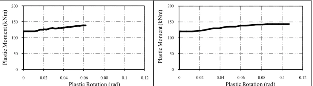
the composite sections (Figure 5). Axial load and moment interaction curves of plain and CFRP wrapped columns for exterior columns and interior columns are given in Figure 6. Moment rotation curves of plain section and CFRP wrapped column sections for exterior and interior columns are given in Figure 7 and 8. The mechanical and geometric properties of CFRP used in the analysis can be seen in Table 1. Three layers of CFRP around the beam and column members is applied while calculating the sectional properties.
0 4 8 12 16 20 0 0.01 0.02 0.03 0.04 St re ss (M Pa ) Strain
Fig. 5 Stress-Strain Relationship of CFRP Wrapped Concrete acc. to Proposed Model10
Table 1 The mechanical and geometric properties of CFRP sheets Characteristic Tensile Strength (MPa) Characteristic Tensile Modulus (MPa) Maximum Tensile Strain (mm/mm) Effective Area Per Unit Width (mm²/mm) Unit Weight (kg/m³) 3430 230000 0.015 0.165 1820 -1000 -500 0 500 1000 1500 2000 2500 3000 0 50 100 150 200 250 300 A xia l F or ce ( kN ) Moment (kNm) 3 plies CFRP wrapped sections Plain sections -1000 -500 0 500 1000 1500 2000 2500 3000 0 50 100 150 A xia l F or ce ( kN ) Moment (kNm) 3 plies CFRP wrapped sections Plain sections
Fig. 6 P-M Interaction Curves of Plain and CFRP Wrapped Columns (left: exterior columns, right: interior columns)
In Case C, in addition to CFRP confinement, beam and column joints are retrofitted by steel bar elements (fuse elements) which results in the reduction of joint shears. These elements are placed only around interior joints for the chosen frame with making an angle of 300 with
RC beams. Steel fuse elements are chosen as tube elements (S220, fy=220 MPa) having a 80
0 50 100 150 200 0 0.02 0.04 0.06 0.08 0.1 0.12 Pl as tic M om en t ( kN m )
Plastic Rotation (rad)
0 50 100 150 200 0 0.02 0.04 0.06 0.08 0.1 0.12 Pl as tic M om en t ( kNm )
Plastic Rotation (rad)
Fig. 7 Moment Rotation Curves of Plain Section and CFRP Wrapped Exterior Column Sections (left: plain column section, right: CFRP wrapped column section)
0 50 100 150 200 0 0.02 0.04 0.06 0.08 0.1 0.12 Pl as tic M om en t ( kNm )
Plastic Rotation (rad)
0 50 100 150 200 0 0.02 0.04 0.06 0.08 0.1 0.12 Pl as tic M om en t ( kN m )
Plastic Rotation (rad)
Fig. 8 Moment Rotation Curves of Plain Section and CFRP Wrapped Interior Column Sections (left: plain column section, right: CFRP wrapped column section)
In pushover analysis, the behavior of the structure is characterized by a capacity curve that represents the relationship between the base shear force and the displacement of the roof. This is a very handy representation in practice and can be visualized easily by the structural engineer. It is recognized that roof displacement is used for the capacity curve because it is widely accepted in practice. Pushover analysis results including capacity curves and plastic hinge mechanisms are shown for three different cases as mentioned before (Figure 9).
0 100 200 300 400 0 0.1 0.2 0.3 0.4 B as eS hear ( kN ) Deflection (m) Bare Frame Enhanced with CFRP Enchanced with CFRP + Haunches
No shear failures were observed in frames case except some joints. This is primarily due to the assumed concrete compressive strength, which happens to be sufficient to prevent shear failures in beam and columns. Thus, the behavior is dominated by flexure and joint shear. As shown in Figure 9, the trend in the capacity curves of all frames is similar. The base shear capacity does not change significantly. The variation in the base shear capacity is less than 10% for the comparison of Case A and Case C. This variation is due to increase in ductility of members and reducing joint shears.
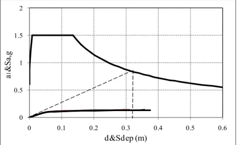
0 0.5 1 1.5 2 0 0.1 0.2 0.3 0.4 0.5 0.6 a 1 &S a, g d&Sdep (m)
Fig. 10 Deflection demands of design earthquake of structure
In Figure 10, the deflection demands of design earthquake given by TSC-20071.
Approximately 320 mm displacement demand is calculated for the structure. In TSC-2007, three different damage levels are defined in terms of plastic strains of concrete and steel. Details of these damage limits are given below;
(a) Minimum damage limit (MN): Upper limit of ultimate compression fiber strain of
reinforced concrete section ( )εcu and strain of steel reinforcement( )εs ;
( )εcu MN =0.0035; ( )εs MN =0.010 ;
(b) Safety limit (SL): Upper limit of ultimate compressive strain of core concrete
( )
εcg and tensile strain of steel reinforcement;( )εs SL =0.040;
( )
0.0035 0.010( s ) 0.0135cg SL sm
ρ
ε = + ρ ≤ ,
(c) Failure limit (FL): Upper limit of ultimate compressive strain of core concrete
( )
εcg andstrain of steel reinforcement;
( )εs FL =0.060;
( )
0.004 0.014( s ) 0.0180cg FL sm
ρ
ε = + ρ ≤ ,
In these equations, ρs is volumetric ratio of transverse reinforcement and ρsw is the required
volumetric ratio of transverse reinforcement according to TSC. TSC-2007 defines four different performance levels which are Light Damage, Moderate Damage, Heavy Damage
Fig. 11 . TSC-2007 performance levels
Performance levels of columns of upgraded frames are shown in figures. In these figures the rotations of all columns and beams are calculated and by using sectional moment-rotation diagrams, real plastic hinge occurrence are decided and plotted in the axial force-curvature diagrams as given in Figure 12, 13, 14 and 15.
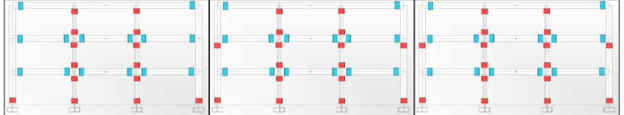
Fig. 12 Plastic Hinge Formation for Three Cases (A,B and C)
Figure 13 Hinge details and deformed shapes for Case A, B and C
Plastic hinge formation mechanisms have been obtained at the displacement points corresponding to global yielding and ultimate displacements. The global yielding point corresponds to the displacement on the capacity curve where the system starts to soften. Plastic hinge formation starts with beam ends at lower stories, then propagates to upper stories, and continues with yielding of base columns. The hinge locations seem to be consistent, significant damage or failure occurs at the columns for all cases. Although hinge formation and roof displacement demand seem almost same in three cases, performance levels are different for all cases according to Figures 14 and 15.
INTERNAL FORCE DISPLACEMENT MN SL FL Light Damage Moderate Damage Heavy Damage Collapse d MN d SL d FL
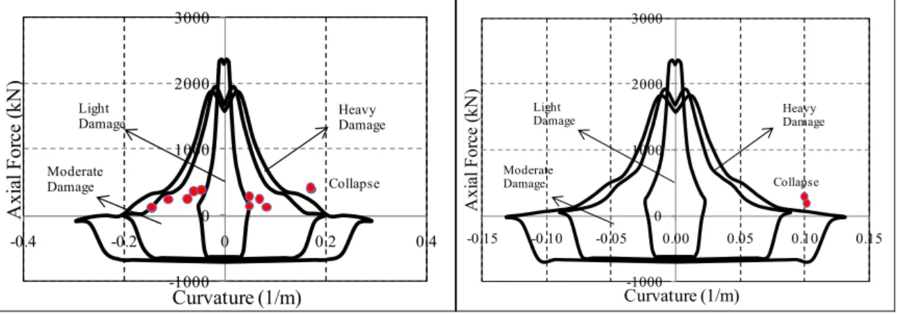
-1000 0 1000 2000 3000 -0.4 -0.2 0 0.2 0.4 A xi al F orc e (k N ) Curvature (1/m) Collapse Heavy Damage Light Damage Moderate Damage -1000 0 1000 2000 3000 -0.15 -0.10 -0.05 0.00 0.05 0.10 0.15 A xia l F or ce ( kN ) Curvature (1/m) Collapse Heavy Damage Light Damage Moderate Damage
Fig. 14 Performance Levels of Case A (Bare Frame) (left: exterior columns, right: interior columns)
-1000 0 1000 2000 3000 4000 -0.4 -0.3 -0.2 -0.1 0 0.1 0.2 0.3 0.4 A xia l F or ce ( kN ) Curvature (1/m) Collapse Heavy Damage Light Damage Moderate Damage -1000 0 1000 2000 3000 4000 -0.15 -0.10 -0.05 0.00 0.05 0.10 0.15 A xia l F or ce ( kN ) Curvature (1/m) Collapse Heavy Damage Light Damage Moderate Damage
Fig. 15 Performance levels of Case C (left: exterior columns, right: interior columns)
Especially, Case C does not have any collapsed column while bare frame (Case A) has many. In addition, the addition of steel haunch elements into system reduces the joint failures. To be able to check the joint shear capacities, a formula proposed by Bedirhanoglu11 is taken into account. In this study, typical beam column joints with different weaknesses were tested and following formula proposed for joint shear capacity made of low strength concrete:
0.5 ´ 1 0.5 ´ m c c g N f f A τ = −
Vj =τmAe
where, fc´= Compressive Strength of the concrete, N = Normal force (Axial is negative sign), Ag = Column cross-section, Ae= Effective Shear area, τm = Joint shear stress capacity, Vj = Joint shear force capacity
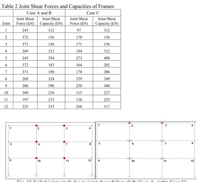
In Table 2, joint shear forces and capacities of Case A and Case C are compared and failed joints are signed in Figure 16. The significant reduction in the number of failed joints can be seen in the figure.
Table 2 Joint Shear Forces and Capacities of Frames
Case A and B Case C
Joint Joint Shear Force (kN) Capacity (kN) Joint Shear Joint Shear Force (kN) Capacity (kN) Joint Shear
1 245 312 97 312 2 372 156 170 156 3 371 156 171 156 4 269 312 194 312 5 245 354 273 408 6 372 183 164 202 7 371 190 170 206 8 269 324 239 349 9 206 396 250 440 10 360 210 115 227 11 197 215 138 225 12 225 335 268 317
Fig. 16 Failed joints (red) due to joint shear failure (left: Case A, right: Case C)
DISCUSSION OF RESULTS
The interior frames of a typical 3 storey building was considered in pushover analyses to represent low and/or medium rise reinforced concrete (RC) school building for study. The following findings can be written: a) The base shear capacity of models with the user defined hinges of three different configurations are almost similar; the variation in the base shear capacity is less than 10%. Thus, the base shear capacity does not increase with the addition of CFRP confinement and steel haunch elements, significantly. b) Displacement capacity
depends on the amount of transverse reinforcement at the potential hinge regions.
Comparisons clearly point out that an increase in the amount of transverse reinforcement improves the displacement capacity. The observations clearly show that the Case C is better than the Case A (bare frame) in reflecting nonlinear behavior compatible with element properties. However, if the Case C model is preferred as seismic retrofit method due to
13 simplicity, effectiveness in terms of time and economy, the engineer should be aware of joint shear failures and possibility of story mechanisms.
As a conclusion, this method seems as a viable solution for the reinforced concrete buildings considered in terms global performance. By introducing such upgrading scheme, the
problems; the necessity of evacuation of the occupants during construction works, limited time availability, time delays and cost overruns can be overcome/reduced in the seismic rehabilitation projects.
REFERENCES
1. TSC-2007, “Turkish Earthquake Resistant Design Code”, Ministry of Public Works, Turkey, 2007, Ankara, Turkey.
2. IBC-2006 International Building Code, 2006.
3. EUROCODE-8, “Design of Structures for Earthquake Resistance”, 1998-1, 2004. 4. Pampanin, Stefano and Christopoulos,Constantin and Chen, Te-Hsiu. “Development and validation of a metallic haunch seismic retrofit solution for existing under-designed RC frame buildings” Earthquake Engineering Structural Dynamics, 35, 2006, 1739–1766. 5. TSC-1975, “Turkish Earthquake Resistant Design Code”, Ministry of Public Works, Turkey, 1975, Ankara, Turkey
6. SAP 2000, “Integrated Software Structural Analysis and Design”, Computers and Structures Inc., Berkeley, California, USA.
7. Ilki, A. “The nonlinear behavior of reinforced concrete members subjected to reversed cyclic loads (In Turkish).”, PhD. Thesis, Istanbul Technical University, 2000, Istanbul, Turkey.
8. Mander, J.B., Priestley, M.J.N., Park, R. “Theoretical stress-strain model for confined concrete.”, Journal of Structural Division (ASCE), 114(8), 1988, 1804-1826.
9. Turkish Standards Institute. TS500. “Requirements for design and construction of reinforced concrete structures”, 2000, Ankara, Turkey.
10. Ilki, A., Peker, O., Karamuk, E., Demir, C. and Kumbasar, N. “FRP Retrofit of Low and Medium Strength Circular and Rectangular Reinforced Concrete Columns”, Journal of Materials in Civil Engineering (ASCE), Vol. 20, No. 2, 2008.
11. Bedirhanoglu, Idris. “The Behavior of Reinforced Concrete Columns and Joints With Low Strength Concrete Under Earthquake Loads: An Investigation and Improvement”, PhD. Thesis, Istanbul Technical University, 2009, Istanbul, Turkey.