An Educational Virtual Laboratory for Sliding
Mode and PID Control of Inverted Pendulum
Metin Demirtas*, Yusuf Altun* and Ayhan Istanbullu** *Department of Electrical and Electronics Engineering, Balikesir, Turkey
**Department of Computer Engineering, Balikesir, Turkey
Abstract—This paper presents a new tool which teaches
sliding mode control (SMC) and proportional-integral-derivative (PID) control to undergraduate and graduate students without laboratory. This educational virtual laboratory tool contains the control of inverted pendulum on the cart. This system is typical example of nonlinear and under-actuated systems. This system is also well known in control engineering for practice of various control theories. At first, the nonlinear dynamic equations of the inverted pendulum are obtained. Then a virtual laboratory tool is designed for SMC and PID. After that the simulation results are analyzed.
Key words—Inverted pendulum, educational virtual
laboratory, sliding mode control, PID control. I. INTRODUCTION
Recently, most control strategies are applied in the linear and nonlinear control systems. The control of inverted pendulum is significant in the control applications. Nonlinear and under-actuated inverted pendulum on the cart problem, especially, is well known as an example system. Therefore, the control of inverted pendulum systems are commonly studied in the control areas. [1–4].
Sliding mode control (SMC) is robust control for nonlinear and linear feedback control method, which has been developed and applied to nonlinear feedback control systems for the last three decades. The SMC approach has been widely used for control design problem. [5,6]. SMC is one of the effective nonlinear robust control approaches since it provides desired system dynamics with an invariance property to uncertainties once the system dynamics are controlled in the sliding mode [7-10]. A SMC is designed so that the system trajectories move onto a sliding surface in a finite time and tends to an equilibrium point along this surface [11].
LabVIEW simplifies the scientific computation, process
control, research, industrial application and measurement applications. Because LabVIEW has the flexibility of a programming language combined with built-in tools designed specifically for test, measurement, and control [12-13]. This connectivity to I/O has also enabled
LabVIEW to be used for control applications. LabVIEW is
an ideal choice used for pragmatic teaching and learning for it supports and serves a wide variety of needs for test, measurement, control and automation applications [14]. The utilization of virtual tools for teaching and learning in engineering has been well accepted by many workers including some work as mentioned in [15, 16].
At the present time, some experiment sets are expensive, and most experiment sets cannot also enable to
be changed their parameters. For example inverted pendulum systems, dc and ac motors etc. Therefore the virtual laboratory is quite significant in order to observe the effects of control parameters. In particular, to well understand the systems which haven’t experiment sets is difficult in teaching. Additionally in the education of these sets, to be understood the effects of the controller parameters on the system by the students are difficult since the students cannot observe the parameters effect on the system. In the literature, there are studies about an educational tool for a lot of systems [17-19].
The inverted pendulum system consists of the rod on the cart for test bed in this study. Firstly its mathematical model is obtained. Then an educational virtual laboratory tool is designed for SMC and PID control of inverted pendulum. While initial conditions of the pendulum angle and cart position are zero, PID and sliding mode control is applied to the inverted pendulum system and the cart is driven by the controller. Thus, the desired angle of inverted pendulum is obtained by the designed educational tool. With this tool, the effect of parameters can be observed in the control system. SMC and PID virtual laboratory tool is arranged for the education of undergraduate and graduate students.
II. DYNAMIC MODEL OF INVERTED PENDULUM
SYSTEM
Figure 1 shows inverted pendulum on the movable cart.
Figure 1. Inverted pendulum cart system
The dynamic model of the inverted pendulum cart system can be deduced by Newton’s method as follows.
1 The matrixes D, E, and F can be represented as follows. , 10 , , (2)
here
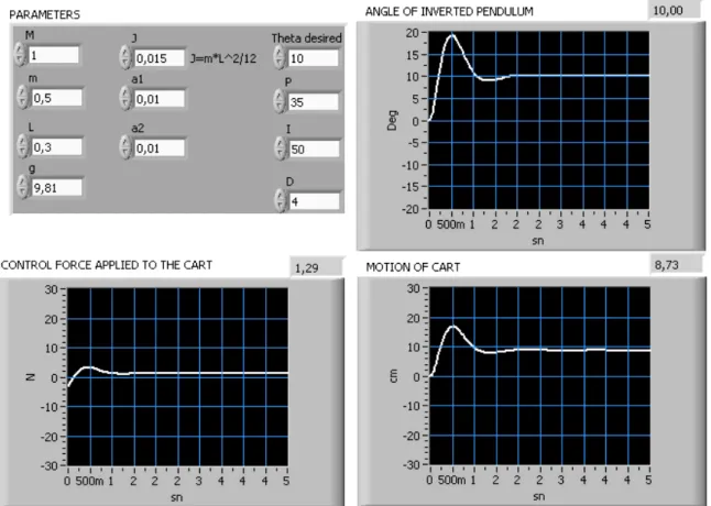
; ;
(3)
Where m is the mass of the pendulum, M is mass of the cart, L is the distance from centre of the gravity of the pendulum, x is horizontal displacement of the cart, g is gravitational acceleration, θ is the pendulum angular displacement, a1 is the viscous friction coefficient of cart,
a2 is the viscous friction coefficient of pendulum, J is
inertia moment of the pendulum, u is the horizontal control force on the cart.
Let θ, θ, x, x According to the
canonical form of a class of under-actuated systems, we can transform the above mathematical model of the system into the following state space expression, briefly.
4 Where , , , is state variable vector; fi(X)
and bi(X) are the nonlinear functions of the state
variables. They are abbreviated as fi and bi in the
following description, which are given as follows.
, (5)
Then we have
, (6) , (7) III. SLIDING MODE CONTROL
To derive the sliding-mode control law which forces the motion of the states to be along the sliding surface s=0; a positive definite Lyapunov function is defined as . If its derivative value is negative definite, then the system is stable and its system trajectory will approach the sliding surface on till converging toward the origin. This is a well-known sliding-mode condition
. 0
Consider the design of a sliding mode controller for the following system:
, , , (8)
s is called the switching function because the control
action switches its sign on the two sides of the switching surface s=0; s is defined as
9
where and is the desired state. c is a positive constant. sign(s) is a sign function defined as
sign 10
1 00
0
10 If the control law meets equation (2), the control strategy adopted here will guarantee that a system trajectory moves toward and stays on the sliding surface s=0 from any initial condition.
IV. SMC AND PIDCONTROL OF INVERTED
PENDULUM
The desired angle of inverted pendulum is obtained using SMC and PID controller. SMC and PID control structures are given by subsection.
A. Sliding mode control
Sliding surface is defined for SMC as follows.
(11) here c is positive constant and x1, x2 as follows .
; 12 The sliding surface and its derivative is obtained as follows by combination equation (11) and (12)
s 13
Either state in equation 14 must be provided for SMC 20 .
0 0 14
If equation (13) is provided, the trajectory reaches as stable and exponentially to sliding surface. If equation (14) is provided, the closed loop system is stable as asymptotic.
The control force is defined as u=U0.sign(s). A
saturation function is used in place of sign function for eliminating chattering problem
B. PID control
Figure 2 shows block diagram of inverted pendulum with classic PID controller.
Figure 2. PID controller
The generated control force by PID controller is
V. THE DESIGNED EDUCATIONAL TOOL
Figure 3. SMC and PID control block diagram
Figure 5. SMC and PID control screen
θd (theta desired) is obtained using LabVIEW program.
This program is designed as an educational tool. Figure 3 shows LabVIEW block diagram for the designed educational virtual laboratory. Figure 4 shows the calculation block subsystem is given in figure 4.
Figure 5 shows inputs screen for SMC and PID controller. This tool has a lot of advantages. All of the parameters of inverted pendulum system can be changed by the tool. Furthermore the parameters of controller can be changed by the tool interface. Thus, the effects of inverted pendulum system and controller parameters on the system can be observed without expensive laboratory.
As shown in figure 5, the tool has inverted pendulum and controller parameters. Where we can change M, m, L,
g, a1, a2, J, θd, U0 and c. Hence we can observe their
effects on angle of the inverted pendulum and the settling time.
VI. THE EDUCATIONAL TOOL EXAMPLE
In this section the educational tool example is given for different parameter. The chosen inverted pendulum parameters are given in table I and III. And the chosen SMC and PID control parameters are given in table II and IV.
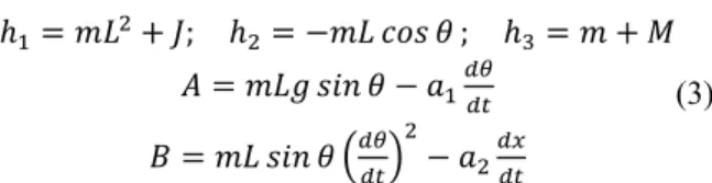
Initial conditions are θ=0 and x=0. The tool results are shown in figure 6, 7, 8 and 9 for SMC and PID control of the inverted pendulum. Where θ, x, u outputs are given as degree, centimeter, newton respectively.
Figure 6. The system outputs with SMC for the parameters table I and II SMC interface PID control interface
Figure 7. The system outputs with PID controller for the parameters table I and II
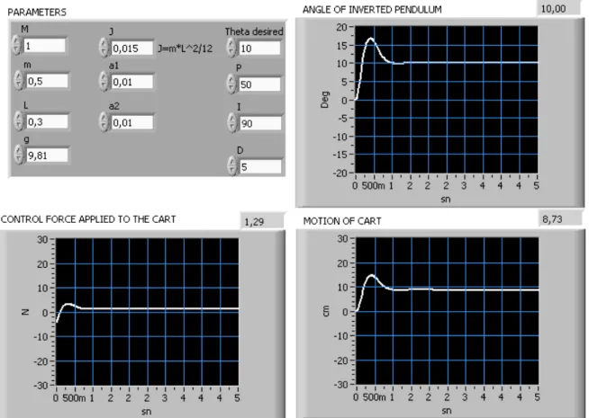
Figure 9. The system outputs with PID controller for the parameters table III and IV
Figure 6 and 7 show graphs of θ, x, u for first parameter values in table I and II. Figure 8 and 9 show the results for second parameter values in table III and IV. As shown in figure 6, 7, 8 and 9, θd can be obtained by
changing the controller and system parameters in the tool. This educational virtual laboratory tool shows each parameter effect on inverted pendulum system.
PID controller coefficients are quite important for the system. Therefore, the effects of P, I and D coefficients on inverted pendulum system can be observed and analyzed by designed the educational tool packet. Similarly the choice of c coefficient is crucial for SMC. c must be determined very well due to the fact that it affects system stability. Changing the coefficients of two controllers by the designed tool’s button, inverted pendulum outputs are observed as shown figure 6, 7, 8 and 9. So the outputs of PID and sliding mode controller can be compared. In addition; changing inverted pendulum parameters, pendulum outputs can be observed.
Consider the problem of teaching sliding mode controller. During the lecture session, the lecturer has a limited amount of time in which to explain and illustrate the results of sliding mode control. Often the students will ask for understanding the effectiveness of the parameter changes on the sliding mode and PID controller. A request that may not be practical given the time constrains. The module on sliding mode and PID control provides a practical solution to this works.
TABLE I.
FIRST PARAMETER VALUES OF INVERTED PENDULUM
M 1 kg m 0.5 kg L 0.3 m g 9.81 a1 0.01 N/m/sec a2 0.01 N/m/sec J 0.015 kg.m2 θdes 100 TABLE II.
FIRST PARAMETER VALUES OF PID AND SMC
c 60 U0 10 P 50 I 90 D 5 TABLE III.
SECOND PARAMETER VALUES OF INVERTED PENDULUM
M 1 kg m 0.5 kg L 0.3 m g 9.81 a1 0.01 N/m/sec a2 0.01 N/m/sec J 0.015 kg.m2 θdes 100
TABLE IV.
SECOND PARAMETER VALUES OF PID AND SMC c 40 U0 10 P 35 I 50 D 4 VII. CONCLUSION
In this paper, an educational virtual laboratory tool is designed for SMC and PID control of inverted pendulum. The tool enables users to change parameters of inverted pendulum and controller coefficients. The user interface shows the outputs as graphical. This tool helps students to improve through their understanding for SMC and PID control of inverted pendulum.
The virtual laboratory is useful for paperless laboratory with reports written. Virtually experimenting is possible. The main objective behind our virtual laboratory development project was to allow undergraduate and graduate students without any previous programming experience about sliding mode control of inverted pendulum system.
The students can understand the differences between PID and sliding mode controller to applied the inverted pendulum system by using the designed virtual laboratory tool.
ACKNOWLEDGMENT
This work was supported by project ERRL -European Remote Radio Laboratory-TR/06/B/F/PP/178036 from EU LdV funded and Balikesir University-BAP (2008-09).
REFERENCES
[1] M.E Magana, F Holzapfel, “Fuzzy-logic control of an inverted pendulum with vision feedback”, Education, IEEE Transactions on Volume 41, Issue 2, pp:165-170, May 1998.
[2] H. Gao, X. Wang, “Simulation research on extension adaptive control of inverted pendulum”, Intelligent Control and Automation Fifth World Congress, Volume 1, pp:437 – 439, 15-19 June 2004 [3] W Rekdalsbakken, “Feedback Control of an Inverted Pendulum
with the use of Artificial Intelligence Computational Cybernetics, IEEE International Conference, pp:1-6, August. 2006.
[4] W. Jun-feng, L. Chun-tao, “Robust Output-feedback Control of Inverted Pendulum”, Industrial Electronics and Applications, ICIEA 2nd IEEE Conference, pp:1027 – 1030, 23-25 May 2007 [5] O.Kaynak, K. Erbatur and M. Ertugrul, "The fusion of
computationally intelligent methodologies and sliding-mode control-A survey," IEEE Transaction on Industrial Electronics. Volume 48, pp: 4-12, February. 2001.
[6] V. M. Panchade, L.M. Waghmare, B. M Patre, P. P. Bhogle, “Sliding Mode Control of DC Drives”; Mechatronics and Automation 2007 International Conference, pp:1576 – 1580, 5-8 August. 2007.
[7] V. I. Utkin, “Sliding mode control design principles and applications to electric drives,” IEEE Trans. Ind. Electron, Volume 40, pp:23–36, February.1993.
[8] J. J. E. Slotine and W. Li, “Applied Nonlinear Control”, Englewood Cliffs, NJ: Prentice-Hall, 1991.
[9] C. K. Lai and K. K. Shyu, “A novel motor drive design for incremental motion system via sliding-mode control method,” IEEE Trans. Ind. Electron, Volume 52, no. 2, pp: 449–507, April 2005.
[10] F.-J. Lin, L.-T. Teng, and P.-H. Shieh,, “Intelligent Sliding-Mode Control Using RBFN for Magnetic Levitation System”, Industrial Electronics, IEEE Transactions on Volume 54, Issue 3, pp:1752 - 1762. June 2007.
[11] A. Jafari Koshkouei and A. S. I. Zinober, “Sliding mode controller-observer design for SISO linear systems”, Int. J. systems Science, Volume 29, pp:1363-1373, 1998.
[12] P. Thepsatoml, A. Numsomran, V. Tipsuwanpo. and T. Teanthong, “DC Motor Speed Control using Fuzzy Logic based on LabVIEW”, SICE-ICASE International Joint Conference, in Bexco, Busan, Korea, pp: 3617-3620, 18-21 October 2006. [13] H. Guruler, A. Istanbullu, O. N. Yigitbasi and O. K. Ersoy,
“Virtual instrument application in industry and data acquisition (In Turkish)”, International VII. Turkish symposium on artificial intelligence and neural networks, pp 69-71, July 2-4 2003. [14] A. See, “Rapid Prototyping Design and Implementation of a
Motion Control Integrated With an Inexpensive Machine Vision System”, IMTC – Toolation and Measurement Technology Conference Ottawa, Canada, pp: 2065-2070, 17-19 May 2005 [15] D. Gillet, H. A. Latchman, Ch. Salzmann, and O.D. Crisalle,
“Hands-on laboratory experiments in flexible and distance learning”, Int. J. of Engineering Edu, Volume . 90, No. 2, pp:187-191, 2001.
[16] A. Istanbullu, I. Guler, “Multimedia based medical instrumentation cource in biomedical engineering”, journal of medical systems, Volume 28, Number 5, pp 447-454, 2004.
[17] Ch. Salzmann, D. Gillet and P. Huguenin, “Introduction to real-time control using LabVIEW with an application to distance learning”, Int. J. of Engineering Edu, Volume 16, No. 3, pp: 255-272, 2000.
[18] L. Foulloy, , R. Boukezzoula, S. Galichet, “An educational tool for fuzzy control“, Fuzzy Systems, IEEE Transactions on Volume 14, Issue 2, pp:217 – 221, April 2006
[19] C. Elmas, M. A. Akcayol, “PC based educational tool for a switched reluctance drive with fuzzy logic”, International Journal of Electrical Engineering Education, Volume 40 Issue 3, pp:208-219, July 2003.
[20] C.C. Ko, B.M. Chen, J. Chen, Y. Zhuang,, K. Chen Tan, “Development of a web-based laboratory for control experiments on a coupled tank apparatus Education”, IEEE Transactions on Volume 44, Issue 1, pp:76 – 86, February 2001
[21] I. Senol, M. Demirtas, Sabir Rustemov, Bilal Gumus, “Position control of induction motor a new-bounded fuzzy sliding mode controller, COMPEL, Volume 24, Number 1, pp:145-157, 2005.
Ph.D. deg Technica He w Telecomm Balikesir research Departme Engineeri he was a Diyarbak Assistant Departme Engineeri interests control o sliding m Electrical Balikesir He has Balikesir and Elec since 200 control s mode con gree in Electr al University, I worked as munication b and Mugla, assistant at ent of El ing, Manisa, as research a kir, Turkey. H t Professor at ent of El ing, Balikesi are in areas of ac motor d mode control. K th E E Z U T c th l and Electr University, B s been worked University, tronics Engin 06. His resea systems, inte ntrol. Dr. Metin born in Mu received the Electrical En the Yildiz Istanbul, Tu the M.S. deg Engineering Kocaeli Univ Turkey, in rical Engineer Istanbul, Turk an enginee between 1989 , in Turkey. t Celal Bay lectrical an Turkey. From assistant at D He is curren t the Balıkesi lectrical an ir, in Turkey s of power drives, intellig Yusuf Altu Karabuk, Turk he Bachelor Electrical an Engineering Zonguldak University, Turkey, in currently doi hesis, in D ronics Engin Balikesir, Turk d as Research in Departmen neering, Balik arch interests elligent contr n Demirtas w us, Turkey. H B.E. degree ngineering fro z Universi urkey, in 198 gree in Electric from t versity, Kocae 1996 and t ring from Yild key, 2002. er at Turki 9 and 2004 He worked yar Universi nd Electron m 1998 to 200 Dicle Universi ntly working ir University, nd Electron y. His resear electronics a gent control a un was born key. He receiv r’s degree nd Electron from t Karaelm Zongulda 2005. He ing his mas Department neering, at t key. Assistant at t nt of Electric kesir, in Turk are in areas rol and slidi
was He in om ity, 89, cal the eli, the diz ish in as ity, nics 04, ity, as in nics rch and and in ved in nics the mas ak, is ster of the the cal key of ing th of be Co U La pr in el m he University o f Electronic etween 2001 a He currently omputer Eng niversity, Tur He has parti aboratory pro roject partner. His current nvestigation of ectronic and mobile learning Dr. Ay born in 1972. H undergradu his Ph.D f Computer Departmen University He wor of Mugla, Tu and Comput and 2006. y works as an gineering De rkey. icipated in Eu oject (EU LdV t research f information d computer e g and intellige yhan Istanb Kutahya, Tu He receiv uate degree ( from the Elect
Science nt of th y (2003), Turk rked as an ins urkey in the D ter Science n Assistant Pr partment of uropean Rem V) and he has interests inc technologies engineering e ent tutoring. bullu was urkey, in ved his 1993) and tronic and Education he Gazi key structor at Department Education rofessor in Balikesir mote Radio s acted as clude the to support education,