Reflection coefficient for a Iossy liquid-lossless isotropic
solid interface
Abdullah Atalar
Edward L. Ginzton Laboratory, Stanford University, Stanford, California 94305 (Received 4 October 1978)
A theoretical treatment of the reflection problem at a lossy liquid-lossless isotropic solid is given. The calculation results indicate that the reflection coefficient has a peak greater than unity. A physical explanation is proposed which also leads to the prediction that at some critical liquid attenuation a Rayleigh wave propagating on the solid surface will not leak into the liquid.
PACS numbers: 43.20.Fn, 68.25. q-j, 68.45. q- w
INTRODUCTION
The reflection coefficient for a plane wave obliquely
incident at a plane interface between a liquid and a solid has been intensively studied. The solution for the loss- less case can be found in some texts such as that by
Brekhovskikh. • The same problem for the lossless
liquid-lossy solid has also been the subject of several
paperso •'ø4 Experimentally observed dip at the Rayleigh
angle has been explained by the presence of loss in the solid. At high frequences liquid loss becomes signifi-
cant s and therefore enters the problem. In this paper a
treatment of the problem for lossy liquid-lossless solid
will be givenø
I. THEORY
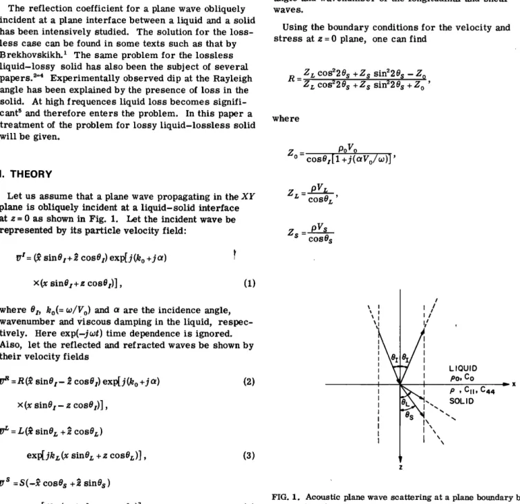
Let us assume that a plane wave propagating in the XY
plane is obliquely incident at a liquid-solid interface
at z--0 as shown in Fig. 1. Let the incident wave be
represented by its particle velocity field:
Vt= (} sin0t+ •. cos0t) exp[j(k o +ja)
where Or., Os, kr.(=w/Vr.), ks(=w/Vs) are the refraction
angle and wavenumber of the longitudinal and shear
wave So
Using the boundary conditions for the velocity and stress at z = 0 plane, one can find
R=Zr.
C0S220S
+Z$
sin220s
--Z o
Zr. c0s220s +Z s sin220s + Z o '
where
Z o
=
cosOt[1OoVo
+j(OtVo/w) ] 'Zr.- pVr.
cosOr. '
Z s - pVs
cosO sx(x sinOt+ z cosO•)], (1)
where 0•, ko(= w/Vo) and a are the incidence angle,
wavenumber and viscous damping in the liquid, respec-
tively. Here exp(-jwt) time dependence is ignored. Also, let the reflected and refracted waves be shown by
their velocity fields
•=R(• sinS•- • cos0•) exp[j(ko +jot)
x(x sinOt- z cosOt)],
(2)
•r • = L(• sinOz + j cos0r.)
exp[jkl;(x sin0r. + z cos0r.)], (3)
/ys =S(-• cosO s + • sinO s )
exp[jks (x sin0 s + z cos0 s )], (4)
/ • I • I II • I
\x
x
LIQUID Po, Co P , CII, C44 SOLIDFIG. 1. Acoustic plane wave scattering at a plane boundary be- tween a liquid and an isotropic solid.
Note that these expressions can be obtained from the
lossless results • by cha•ging k o with k o +)c•.
Snell's Law takes the form
[(1
+]--•- (Vø)'•
'aVø)]
sinSx
= Vt. = Vs
(sinSr.)
(sinSs)
To satisfy this equation sin•r. and sin• s must be com- plex and therefore cOS•r. and cOSts have to be complex
as well: 1/2 sin 2 8 ! 8 I 6Hz 2 6Hz 4 6Hz ... 86Hz 0.2 0.25 ." I' • ..:. ! ... • 0.35 Sin 81 for i = L, S. Examining the forms of the refracted waves in Eqs.
(3) and (4) helps us select the proper sign for cos •o For sin• • < (Vo/V•) , cos • must have a positive real
part so that the refracted waves have a k vector with a positive z component. On the other hand, for sin•
>(Vo/V•) , cos 8• has to have a positive imaginary part.
This condition makes sure that the refracted waves die
out as z goes to infinity. Since cos 8• changes sign
at the critical angles while its magnitude is nonzero, one may expect discontinuities in the reflection coeffi- cient. 0.20 0.25
a•,o ..
...
,"f••
• a35 Sin 81 l! I II. RESULTSAn HP9820A calculator program has been written to
perform the numerical calculations summarized above.
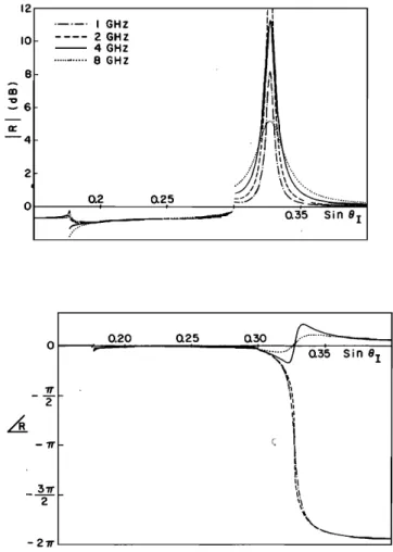
Figure 2 shows the reflection coefficient amplitude and phase for the water-YAG interface at 1, 2, 4, and 8
GHz. (We assume that ot/f 2= 22 x 10 '•5 for waterø) No- tice that the reflection coefficient magnitude for incident
angles near Rayleigh angle is greater than one! This
peculiar behavior can be explained by the "Schoch dis- placement. "6 The Schoch displacement is the acoustical counterpart of the optical "Goos-H'Anchen shift." This
phenomena is associated with the reflection of a well-
collimated beam incident on an interface at the Rayleigh critical angle. The reflected beam undergoes a sizeable lateral shift from the position predicted by geometrical considerations. This displacement is actually created
by the reradiation of the Rayleigh wave from the region
outside that ensonified by the incident beam. For the lossless case an analytical expression can be obtained
for this lateral shift, •,6
81
_2X
o p r(r-s) •/2 l+6s2(l_q)_2s(3_2q)
;r Po s(s-1) s-q
(5)
FIG. 2. Amplitude and phase of the reflection coefficient for H•.O-YAG interface at 1, 2, 4, and 8 GHz.
(a)
(b)
FIG. 3. Illustration of a setup to measure the reflection coef- ficient (a) at an angle greater than the Rayleigh angle, (b) at the Rayleigh angle. The liquid path in (b) is less than that in (a)
by an amount A s sin
where
r = (V•/¾o) •' q = (Vs/Vz ,)2.
Here V s represents the Rayleigh wave velocity.
We will assume that A s is still given by Eqo (5) under
small loss conditions. This is a good approximation,
because the phase of the reflection coefficient changes
very slightly
with the introduction
of small losses.
•'
Figure 3 depicts a setup to measure the reflection coef-
ficient of the interface at different angles. If the liquid
medium is lossy, the attenuation in the liquid path must be accounted for, and the measured reflection coeffi-
cient has to be normalized accordingly. In Figø 3(a) an incidence angie larger than the Rayleigh angle with a
liquid path of 2d is shown. In this case the lateral shift
is negligible and we obtain a unity reflection coefficient
after normalizationø In (b) the incidence angie is the
Rayleigh angieø Therefore a lateral displacement will take place, and the liquid path will be reduced by A s sin es, but for normalization the full 2d length is usedø In this case we expect to obtain a reflection coefficient larger than unity by an amount determined by the atten- uation in the path A, sin es.
The reflection
problem
involv{ng
a lossless
liquid
and
a lossy solid is discussed in the literature. 2'4 The re-
ported dip at the Rayleigh angle follows from the heuris- tic argument given above as well. In Fig. 3(b) the wave propagates a distance A s in a lossy medium, and there-
fore this wave will have smaller amplitude at the re-
ceiver compared to the case shown in (a).
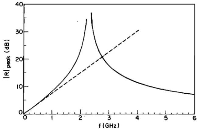
The solid curve in Figø 4 is a plot of the reflection co- efficient peak value as a function of frequency for the water-YAG interface. For this case e• = 19.09 ø and
A, = 81.04},
o. Hence
the water path
difference
is A, sine•
=26.5}, o. Our argument predicts a peak amplitudeexp(•
f •'
A
s
sine•)
=
exp(8o79 x 10'•øf) oThis is also plotted in Fig. 4 as a dashed lineo The agreement between the curves at low frequencies sup- ports the simple explanation mentioned above. At higher frequencies, expression (5) loses its validity since it is
true for low loss cases onlyo
The peak amplitude goes to infinity at some critical
frequencyø This frequency is analogous to the "frequen-
cy of zero reflection" observed on lossy solids. Our
argument tells us that at this frequency the Schoch dis-
40 30 o 20 •0 0 0 ... ! , ! , , , .... , ... i 2 3 4 5 6 f (GHz)
FIG. 4. The value of the reflection coefficient amplitude at the
Rayleigh angle (solid line) fo• H20-YAG interface as a function
of frequency. Dashed line is an approximation to this curve valid at low frequencies.
placement is infinite. That is to say, for some critical attenuation the Rayleigh wave will not leak back into the liquid. This may seem to violate the reciprocity princi- ple. However the reflection coefficient peak at this fre- quency is infinitely narrow. In other words one has to use infinitely wide beams (or plane waves) to excite the Rayleigh wave. Thus, infinite power is involved and the reciprocity principle does not apply. Nevertheless, one can conclude that if a Rayleigh wave is excited by some
other means it will not leak into the liquid provided the
attenuation in the liquid is at that critical valueø For higher frequencies the peak amplitude decreases to approach to unity (see Fig. 4), suggesting that for a very lossy liquid the Schoch displacement would not be
presentø
III. CONCLUSIONS
Theoretical calculations show .that the reflection coef-
ficient for a lossy liquid-lossless solid interface has a peak at the Rayleigh angle. This peak value is greater than unity and its presence is explained by the Schoch displacement. The magnitude of the peak depends on the liquid attenuation and it goes to infinity at some critical
attenuation valueø The proposed physical explanation predicts that at that critical point, a Rayleigh wave pro- pagating on the solid surface will not leak into the liquid.
ACKNOWLEDGMENTS
The author wishes to thank Professor Co F. Quate for
a critical reading of this manuscript, and J. Fraser and V. Jipson for helpful discussionsø This work was sup- ported by the Air Force Office of Scientific Research.
1L. M. Brekhovskikh, Waves in Layered Media (Academic,
New York, 1960).
2V. M. Merkulova, Sov. Phys.-Acoust. 15 (3), (1970). 3G. Mott, J. Acoust. Soc. Am. 50, 820 (1971).
4F. L. Becker and R. L. Richardson, J. Acoust. Soc. Am. 51,
1610 (1972).
5j. Attal and C. F. Quate, J. Acoust. Soc. Am. 59, 69 (1976).
6A. Schoch, Ergeb. Exact. Naturwiss. 23, 127 (1950).