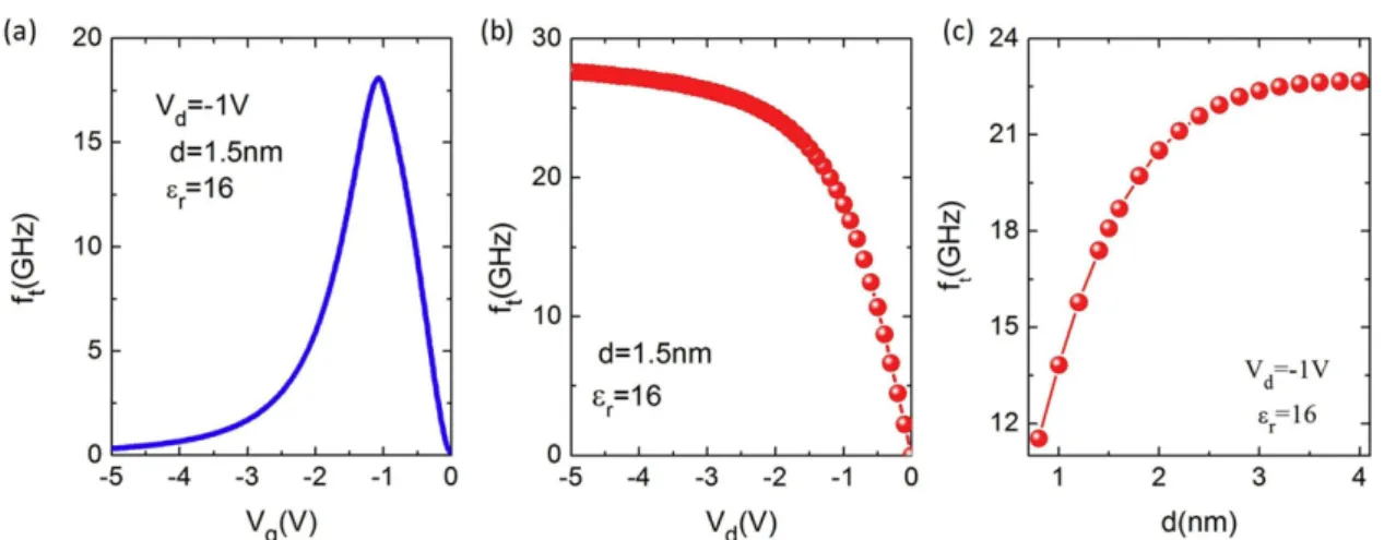
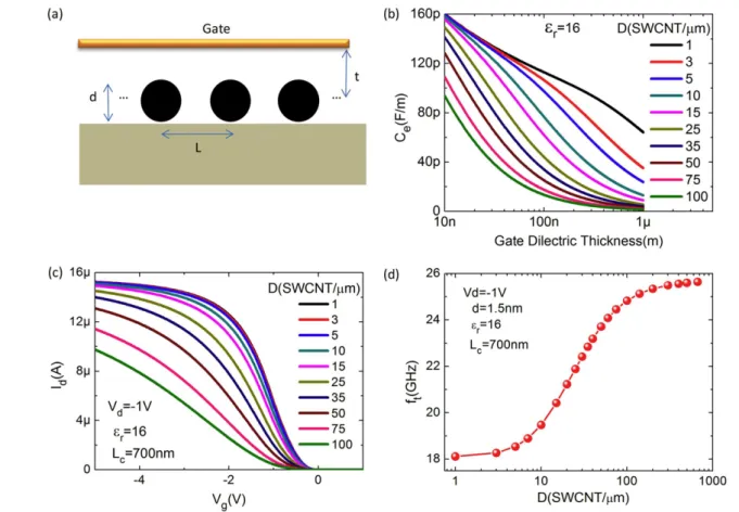
High frequency performance of individual and arrays of single-walled carbon nanotubes
Tam metin
Şekil


Benzer Belgeler
The pro- posed approach applies progressive morphological filtering to compute a normalized DSM from the LiDAR data, uses thresholding of the DSM and spectral data for a
We model the problem as a two stage stochastic mixed integer nonlinear program where the first stage determines the departure time of new flights and the aircraft that is leased..
İlio-femoral, femoro-popliteal arter bypass operasyon yapılan 4 hastada ilio-femoral arter by- pass için PTFE grefti, distaldeki femoro-popliteal arter bypass ameliyatı
Similarly, later Welsh law also made a distinction between galanas, which means both the feud and the wergild payment, and sarhaed (or sarhad), which refers both to an
achieves a broad display of the phase stability of the bipolaron state as a function of the effective dimensionality extending from the bulk to the extreme limit of strict
As a consequence of that study, a microfluidic channel network with five inlet reser- voirs (one for TPP solution, reservoir A, four for chitosan solu- tion, reservoirs B) and two
In conclusion, we have studied the structural, electronic, and optical properties of fully hydrogenated stanene, stanane, and armchair stanane nanoribbons (ASnHNRs) by DFT-
The Kurdish issue, which has been a central problem in the Turkish Republic since its establishment in the early 1920s, has evolved into a major challenge in Turkey’s domestic
