© TÜBİTAK
doi:10.3906/fiz-1806-17 h t t p : / / j o u r n a l s . t u b i t a k . g o v . t r / p h y s i c s /
Research Article
THz applications of multimode laser diodes: a review
Turgut ÖZTÜRK1,∗,, Osamu MORIKAWA2,1Department of Electrical-Electronics Engineering, Faculty of Engineering, Bursa Technical University,
Bursa, Turkey
2Chair of Liberal Arts, Japan Coast Guard Academy, Kure, Japan
Received: 20.06.2018 • Accepted/Published Online: 23.05.2019 • Final Version: 02.08.2019
Abstract: Investigations are ongoing to develop cheaper THz time-domain spectroscopy (THz-TDS) systems. In this context, many studies have been published in which multimode laser diodes (MLDs) are used as light sources in THz-TDS systems. There is another method for cost-reduction. Photomixing employs two single-mode LDs and does not require a pulse laser, and then realizes a reduced-cost system. A comprehensive report has been presented by examining the work done up to now. In these studies, it has been shown that the characteristics of MLDs, the effects of antenna structures on THz signal production, the difficulty of collimation of the MLD radiation beam, and the contribution of fiber-based systems are of utmost importance. It has also been determined that mode spacing has a significant role in THz radiation generation. In addition, successful SN ratio enhancement and imaging studies have shown that a more compact and cheaper THz-TDS system can be established using MLDs as a light source. Macor and RC51HF samples have been analyzed using a MLD-TDS created in the same way as in previous studies and results are given.
Key words: Multimode laser diode, time domain spectroscopy, THz radiation, photoconductive antenna
1. Introduction
It will be possible to use terahertz (THz) technology products widely in the near future by taking advantage of THz rays with the increase of developing technology and research opportunities. THz waves have unique properties, such as being able to pass through some materials that are not found in other parts of the electromagnetic spectrum and reflecting close to 100%, being harmless compared to X-rays, and having the ability to distinguish between different materials. THz waves with these features will provide new advantages in airport safety, identification of hazardous samples, medical imaging, and quality control in the food industry [1–5].
Although many studies have been performed about the regions of electromagnetic spectrums, studies on the terahertz frequency region have accelerated in the last 30 years. The most important technological restriction is the deficiency of sources that generate THz radiation [3]. Nevertheless, the lack of a detector was also a technical problem. Light sources were improved by developing technology and THz radiation has become a center of interest. However, recent accomplished works in this area were not cheap, simple, or stable enough because of the light sources used. In particular, a femtosecond laser source is still more expensive than single-mode or multimode laser diodes. Therefore, a multimode laser diode (MLD) can be used as a light source to solve these problems because the MLD has many advantages such as being compact, cheap, and stable [4,6].
∗Correspondence: [email protected]
The fundamental feature of the MLD that makes the MLD the irradiating source for THz generation is rapid fluctuation in optical power. The MLD was proposed first by Hangyo for use in THz time-domain spectroscopy (THz-TDS) systems instead of femtosecond lasers and it is also used for THz signal generation processes [7,8]. The signals obtained by MLD-TDS systems indicate similar behaviors with signals obtained by conventional THz-TDS [7,9]. The spectrum of the pulse is in the range of 0.1–1 THz. Advantages of MLDs can be listed as follows [10]:
• The laser diode is compact since it consists of a chip, heat sink, outer protective can, and three pins. • The laser diode can be driven with a power supply that has lower electrical power compared with the
needed power supply for other lasers.
• The laser diode can perform with electrical currents of lower values. • There is a possibility of direct modulation with applied current. • It is very cheap compared to other lasers.
There are some disadvantages as well as the advantages mentioned above. MLDs are very sensitive to temperature and the angle of emission of radiation is very large, which is easily solved by using a collimating lens [10]. The specified advantages of MLDs were used for obtaining continuous wave (cw) THz radiation, sample analysis, and 2D imaging processing in THz-TDS. The signals by THz-TDS with MLDs are very weak compared to those with pulse lasers. To keep the SN ratio high, the time constant of the lock-in amp must be long, and this makes measurement time long.
Initially, it was aimed to increase the amplitude of the THz signal and frequency band width by using MLD-TDS systems. The emphasis is particularly on the collimation of the laser beam, the effects of different antenna structures, and the efficient production of laser diodes of different brands. In spite of detailed and general information about the electrical and optical equipment being important for the creation of the experimental system, there are also some studies that have not provided the required information, such as MLD features and antenna types [4,6,7,11–14]. The results obtained from MLD-TDS systems are compared with femtosecond lasers in terms of radiation power, spectral width, scan time, radiation efficiency, and stability of the system [6,11,13,15]. While the radiation power of MLDs still needs to be improved in terms of spectral width (fs laser ∼10 nm, MLD ∼2 nm) and radiation efficiency, the MLD has significant advantages due to its features such as low cost, compactness, and stable structure, which are emphasized in each study.
In this study, the MLD, which is used as a light source for THz-TDS systems, has been discussed extensively and measurements of new materials with the MLD-TDS system have been performed in the THz frequency range. In particular, the originality of each prior study has been briefly explained. In this context, the mode spacing of the MLD has been found to play a key role in THz signal generation. In addition, Macor and RC51HF samples have been measured for THz frequency for the first time and the analysis results are given. New suggestions are provided for system stability and faster signal scanning in MLD-TDS systems.
2. Use of MLDs in previous studies
The main reason for the great development of THz technology in recent years is the improvement in electronic and optical technologies. The conventional THz-TDS system developed in the direction of these improvements is still expensive due to the most important component: femtosecond lasers. Although MLD-TDS is weaker
than conventional THz-TDS in terms of radiant power, radiation efficiency, and spectral width, it has been shown in some studies that these points can be improved [11,16–18]. In this context, the recommended light source for these adverse situations is the smaller, simpler, less expensive, stable, and commercially available MLD.
When studies on MLDs are examined over a period of more than 15 years, targeted studies in different experimental systems can be grouped as focusing on THz production, sample analysis, and 2D imaging. To date, the Morikawa and Koch research groups have studied this topic. These two groups gave different names to the new systems they developed, such as Poorman’s THz-TDS, quasi-TDS (QTDS), and MLD-TDS [4,6,8,15,16,18,19].
The basis of the THz generated by the aid of a photoconductive antenna (PCA) is to create a current ripple in the picoseconds time interval in the device. In order to do this, the MLD’s sudden fluctuation of beam is used to change the intensity of the beam [19,20]. A MLD with this feature was first proposed by Hangyo to produce cw THz radiation. It has been shown that the PCA stimulated by the MLD can generate THz signals, measured by a bolometer that is sensitive to temperature change [7,8]. In this first study, Hyodo’s experimental setup was used and the MLD was preferred instead of a microchip laser as a beam source [7,21]. In the following processes, the same systems were established and signal levels by various types of antennas were compared, while the transmittances and refractive indexes of the sample were measured for sample characterization [11,15,22].
In the MLD-TDS system, the first antenna generation-antenna detection system was installed by using an antenna instead of a bolometer, and both the THz signal and the refractive index of a sample were measured [20]. In studies conducted with the antenna-antenna system, increasing the bandwidth of the cw THz radiation frequency and sample characterization were at the foreground [4,14,16,18,19,23,24]. As a different measurement system, the single-mode optical fibers were employed to increase continuous component in the signal spectra, which are favorable for spectroscopy [12,13,17,23,25]. Furthermore, antenna system without fibers were compared for the first time and it was shown that the fiber-based system is advantageous [12]. After the publication of [12], it was concluded in [6] that systems with spatial filters were preferable compared to those with fiber. Signal-to-noise ratio (SNR) was studied to improve the amplitude of the signal [6,12,14,16,22,23]. As a result of comparisons, the spatial filter increased the amplitude of the continuous components in the radiation spectrum and the SN ratio was improved by 13 times compared to the fiber-based system [6]. In addition, the results of the proposed system were compared with the results obtained with the Drude model to demonstrate the accuracy [11,14,24].
Since the power of the THz radiation is proportional to the square of the irradiating power of the laser light it is necessary to obtain the THz signal at the desired level and to increase the SNR ratio [13,15]. A MLD with high optical output power may be preferred for this requirement.
The employment of fiber optics enables improvement of usability. The sensitive adjustments of focusing lens in front of the photoconductive antennas are no more required. To avoid the damage of the photoconductive antennas, the power of the MLD is adjusted by varying the driving current. The employment of fiber optics enables improvement of usability. The sensitive adjustments of focusing lens in front of the photoconductive antennas are no more required.
When the studies on the band width of the generated THz signals are examined, it is observed that the frequency band width of the signal generated is about 0.5–1.0 THz at most [16–18,25]. For the first time, sample thickness information was obtained by MLD-TDS [4]. Although the first 2D imaging was done by Hu and Nuss,
after the first MLD-TDS system was developed, the SNR was increased and two separate 2D imaging processes were made for a polymeric airbag cover and glass fiber reinforced polymer [4,13,16,26].
In order to increase the frequency band width of the cw THz radiation generated, special methods were tried in some studies and the results were repeated comparatively. In addition, the PCA has been placed somewhat farther back from the focal point of the lens to make the radiation more efficient [6,11,15,23]. The results obtained by using a spatial filter to focus the MLD’s light onto the PCA by collimation were compared with the results obtained using the fiber cable without a spatial filter. In addition, the results obtained with the MLD-TDS system were compared with the results obtained with a free space measurement microwave spectroscopy system to show the important and useful aspects of the MLD-TDS system in the 75–325 GHz frequency range [3].
3. MLD-TDS system
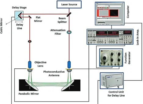
Prior to using the MLD as a light source, the experimental setup is optimized using a mode-locked Ti:Sapphire laser. In the THz-TDS system, PCAs are electrical components, while others are passive components. The experimental setup consists of the generation and the detection arms (paths). On the generation path, there are attenuation filters, objective lenses, the PCA, and parabolic mirrors. On the detection path, are the angular mirror, flat mirror, objective lens, PCA, parabolic mirror, delay stage, and electric motor.
The components used in the MLD-TDS system can be described as follows. The lock-in amplifier is an important device since it enables obtaining phase and amplitude information of the measured signal. The lock-in amplifier can be used to detect and measure very small current/voltage signals at nano levels at constant frequency and phase. The SR830 lock-in amplifier generally used in THz-TDS systems detects the signals in a frequency range of 1 mHz to 102 kHz. This device has a measurement accuracy of 100 fA to 0.5 µ A current.
When the previous studies are examined, two differently shaped PCAs with the same structure are used to generate and detect THz signals. The generation antenna (Batop PCA-44-06-10-800-h) has 800 nm laser excitation wavelength, 44 µ m antenna length, 6 µ m antenna dipole length, and 10 µ m gap width. The detection antenna (Batop PCA-40-05-10-800-h) has 800 nm laser excitation wavelength, 40 µ m antenna length, 5 µ m antenna dipole length, and 10 µ m gap width.
The function generator is used to apply the preloading required for the generation antenna. The preferred voltage value for the generation antenna is ±15 Vpp at 1 kHz. In addition to this, the position of the cube-type beam splitter is adjusted by controlling the delay stage component, which is monitored by the LabVIEW program. There are three important parameters, step size, waiting time, and scan distance, that are controlled via the LabVIEW program for position change. The step size is the measurement of the distance taken by the delay stage unit. The waiting time refers to the time that the delay stage has waited before moving to the next step size after moving along a step size. The scan distance specifies the total size of the path taken by the delay stage. In the case of Morikawa group, the photoconductive antennas are a log-spiral type with a flat photoconductive gap of 5 µ m wide produced by Hamamatsu Photonics. The emitter antennas are applied with an ac voltage of 80 Vpp with a frequency of 11 kHz for lock-in detection.
Parabolic mirrors are used for proper alignment of THz pulses. It is easy to focus the THz beam using the parabolic mirrors. The cubic mirror is usually made of gold for high conductivity. However, in terms of cost, a cubic mirror made of aluminum may be more preferred. The advantage of this mirror is that it has low absorption and high reflection properties. The schematic diagram of a THz-TDS system is shown in Figure 1.
Figure 1. Schematic representation of THz-TDS system.
The following beam, divided into two paths, which are called generation and detection arms, is focused on the antennas by the objective lens. The signals that are radiated from the emitter antenna are directed by the parabolic mirror. The PCA that is based on the semiconductor device can convert the infrared lights to THz. The THz signals emitted from the silicon lens side of the antenna create a THz electric field. The correlation between exciting light intensity and THz electric field is obtained as a function of delay time by the lock-in amplifier. The delay time is used to equalize the paths of the generation and detection beams. The values of current that are imported from the lock-in amplifier are recorded and plotted as THz wave profile versus time by the LabVIEW program.
4. Analyzing MLDs before use in THz-TDS systems
A MLD can operate for tens of thousands of hours when driven by a suitable and stable laser module. It should allow the laser diode to make the necessary changes in the applied current/voltage values [9,16]. Some calculations have to be made for the MLD to be used as a light source instead of a mode-locked Ti:Sapphire laser source. It is necessary to calculate the frequency difference between each mode of the MLD to estimate the THz frequency bandwidth. The wavelength (nm) value of the mode spacing should be obtained with the optical spectrum analyzer (OSA) before calculating the spacing between each mode in the frequency. Since the MLD’s wavelength values are measured by the OSA, the necessary information can be reached through this value.
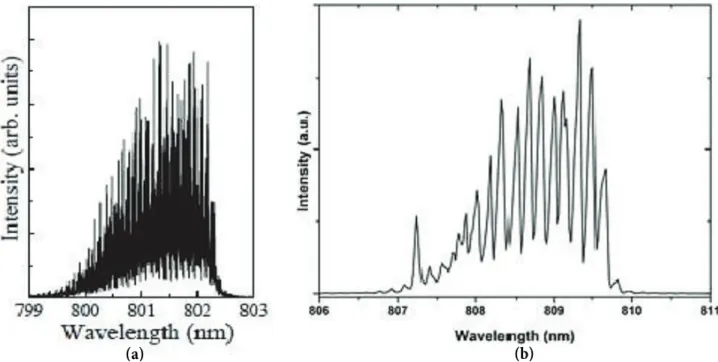
Analysis of the laser diode for the determination of the mode interval needs to be done with the OSA. Since the measurements made with the OSA are in nanometers, it is necessary to convert the mode spacing value given in frequency (GHz) to the wavelength (nm) or the mode spacing value given in terms of wavelength to the frequency (GHz) value. As a result of a commercially available MLD analysis, we have calculated the mode spacing to be 0.16 nm. After making the necessary calculation, the mode spacing value in frequency (GHz) was obtained as 73.4 GHz. The other two groups (Koch and Morikawa) used laser diodes in their experiments with
mode ranges of 0.04 nm (24 GHz) and 0.1 nm (50 GHz), respectively. The signal repetition time was calculated to be 13.6 ps with the help of the corresponding formula for the laser diode. By using the frequency difference value between two modes ( ∆f ) , it is possible to determine the repetition time of the signal to be obtained with the equation TR = 1/∆f . As a result of the analysis, the spectrums of MLD used by Morikawa’s research
group [20] and our MLD, which is commercially available (approximate fee for it is $4) are shown in Figures 2a and 2b, respectively.
Figure 2. The demonstration of mode spacing for two different MLDs.
The spectrums of MLDs of Koch’s research group [4] and our MLD are shown in Figures 3a and 3b. Since the wavelength of the first and last mode value is known, the frequency difference ( ∆f ) was found and the laser diode spectrum was determined as 721 GHz. In this case, the bandwidth during the THz generation process will be about 0.4 THz for our MLD. The spectrum and bandwidth values were obtained as 1 and 0.6 THz for Koch’s research group, respectively.
The THz signal was generated by using the mode-locked Ti:Sapphire laser as a light source after making the connections in the experimental setup as shown in Figure 1. After the necessary values (start and finish points of scan, waiting time/period, and step size) are entered using the LabVIEW program, the data are collected by scanning the signal in the THz-TDS system. The THz electric field and power spectrum graphs obtained as current value according to the obtained data are shown in Figure 4.
When the THz pulse and the power spectrum are examined together, it is observed that the short pulse duration causes the increase in the frequency range. That is, the pulse duration affects the THz generation and there is an inverse relationship between them. The THz frequency was drawn using the Origin software program as shown in Figure 4a. When the time duration is about 1 ps, the THz frequency range will be about 1 THz. The power spectrum of the THz pulse is shown in Figure 4b as the frequency range obtained is about 1 THz.
Figure 3. The spectrum of two different MLDs.
Figure 4. The THz signal generated by THz-TDS: THz pulse (a), power spectrum (b).
5. Measurement results and discussion for MLD-TDS system
Criteria such as efficiency, stability, and inexpensiveness should be considered for common use of the system setup. For this reason, a compact THz-TDS system was established using a cheap, compact, and stable MLD as a light source. The generation of the THz signal in the MLD-TDS system is briefly described as follows after using the MLD as a light source instead of a Ti:Sapphire laser. The MLD-TDS system was successfully established and measurements were made for Macor and RC51HF samples. Furthermore, detailed information of the samples measured by the MLD-TDS system is given in the Table. The thicknesses of Macor and RC51HF samples are 2.22 mm and 9.96 mm, respectively.
Table. The general information about measured samples.
Sample Components and features Application areas
Macor
-Glass; ceramic; mica (silicate)
-Good thermal insulator; stable up to tem-peratures of 1000 ◦C; machinable; will not deform, unlike ductile materials; low ther-mal conductivity, excellent electrical insula-tor; radiation-resistant
Semiconductor; electronics; nuclear; laser ca-vity reflectors; aerospace
RC51HF
-Poly methacrylate imide (PMI) foam (does not contain any CFCs)
-Low density; temperature resistance of up to 220 ◦C; easily machinable; high performance sandwich structures
Antenna applications (from miniature anten-nas in cell phones to large fixed ship-based and stationary antenna structures); radomes; mammography plates
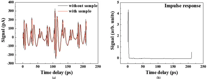
The new THz signal obtained after placing the Macor sample between the parabolic mirrors is shown in Figure 5a with red color as with the sample. The impulse response was obtained as shown in Figure 5b.
Figure 5. Time-domain signal (a) and impulse response (b) for Macor sample.
The same measurement process was repeated for the RC51HF sample as shown in Figure 6. Figure 6a shows the time-domain signal without sample. The impulse response was obtained as shown in Figure 6b. The refractive indexes (n) were obtained for Macor and RC51HF samples as shown in Figures 7a and 7b, respectively. In the MLD-TDS system, the one without sample measurement takes 15 min, which is a disadvantage. The stability of the MLD-TDS method is adversely affected by the large number of components in the system. For example, a thermos-electric cooler should be used to control the MLD temperature. Hence, the heating problem of MLD is removed for long time measurement process. In addition, even if the system is protected in housing, micron size displacement over time can cause a change of the laser beam path. In this case, the accuracy of the measurement will be negatively affected. In addition, since the THz signal is very weak in the MLD-TDS, the SNR is a little poor in the MLD-TDS compared to the conventional THz-TDS, which uses a femtosecond laser as a laser source.
MLD-Figure 6. Time-domain signal (a) and impulse response (b) for RC51HF sample.
Figure 7. Complex refractive index of Macor (a) and RC51HF (b) samples.
TDS system overlap, but the results of the imaginary part of the complex permittivity are better than those of microwave spectroscopy systems. In THz-TDS, measurements below 100 GHz, which are already outside the THz frequency range, are not within the desired range due to poor SNR and they are generally not shared. The MLD-TDS system can be offered for a wide frequency range as the most efficient solution. However, it may be difficult to detect the THz signal if a MLD with a wavelength of 660 nm is used while the PCA’s effective wavelength range is 808 nm.
In conventional THz-TDS, the waveform of THz pulses is measured by scanning the time delay between the generation and detection arms. The measurement of the THz spectrum can last up to 10 min depending on the length of the scanned path since interferometric techniques are used here [27]. Therefore, the measurements are influenced by the sudden fluctuation of the laser source and the measurement environment. By shortening the measurement time with a quick scan these negative effects can be removed. For high-speed imaging, the studies are focused on fast acquisition of THz waveform information. To do this, a fast-acting delay line should be used instead of a delay line with a slow-moving motor [28]. To perform the obtaining of the THz signal
quickly in a MLD-TDS system, the voice coil stage (VCS) can be used, which performs a fast-moving delay process. By using the VCS, the system can scan the signal in the specified range more than 60 times a second [28,29].
6. Conclusion
The published studies about MLDs have been reviewed and it has been determined that the MLD is a good alternative as a light source to create and develop a cheaper THz-TDS system. In addition, two new materials (Macor and RC51HF) were measured with the MLD-TDS system in the range of 0.1–0.8 THz. In order to make the best MLD choice, mode spacing analysis must be done absolutely by using an OSA. Thus, preliminary information can be obtained about the THz signal when an analyzed MLD is used. The desired range of OSA analysis is about 0.04–0.1 nm. Furthermore, special MLDs can be designed for compact and cheap THz-TDS systems, which can be used in many areas, and the stability of the system can be increased.
References [1] Verma, S. S. Phys. Educ. 2007, 42, 259-262.
[2] Chang, Q.; Yang, D. In Progress in Electromagnetics Research Symposium, Hangzhou, China, 2005, pp. 331-335. [3] Ozturk, T.; Morikawa, O.; Ünal, İ.; Uluer, İ. J. Infrared Millim. Terahertz Waves 2017, 38, 1241-1251.
[4] Scheller, M.; Koch, M. Opt. Express. 2009, 17, 17723-17733.
[5] Dragoman, D.; Dragoman, M. Prog. Quantum Electron. 2004, 28, 1-66.
[6] Morikawa, O.; Fujita, M.; Takano, K.; Hangyo, M. J. Appl. Phys. 2011, 110, 063107.
[7] Tani, M.; Matsuura, S.; Sakai, K.; Hangyo, M. IEEE Microw. Guid. Wave Lett. 1997, 7, 282-284.
[8] Hangyo, M. In: 39th International Conference on Infrared, Millimeter, and Terahertz Waves, Tucson, AZ, USA, 2014, pp. 1-4.
[9] Scheller, M.; Stecher, M.; Gerhard, M.; Koch, M. Appl. Phys. B 2012, 106, 81-84. [10] Bartl, J.; Fíra, R.; Jacko, V. Meas. Sci. Rev. 2002, 2, 9-15.
[11] Morikawa, O.; Tonouchi, M.; Hangyo, M. Appl. Phys. Lett. 1999, 75, 3772-3774. [12] Morikawa, O.; Fujita, M.; Hangyo, M. Appl. Phys. Lett. 2004, 85, 881-883.
[13] Shibuya, K.; Tani, M.; Hangyo, M. In 15th International Conference on Terahertz Electronics, Cardiff, UK, 2007, pp. 732-723.
[14] Morikawa, O.; Tonouchi, M.; Hangyo, M. Appl. Phys. Lett. 2000, 76, 1519-1521.
[15] Tani, M.; Morikawa, O.; Matsuura, S.; Hangyo, M. Semicond. Sci. Technol. 2005, 20, 151-163. [16] Scheller, M.; Dürrschmidt, S. F.; Stecher, M.; Koch, M. Appl. Opt. 2011, 50, 1884-1888.
[17] Morikawa, O.; Fujita, M.; Hangyo, M. In 34th International Conference on Infrared, Millimeter, and Terahertz
Waves, Busan, Korea, 2009, pp. 1-2.
[18] Scheller, M.; Koch, M. In Conference on Lasers and Electro-Optics, San Jose, CA, USA, 2010, pp. 2-3. [19] Hangyo, M.; Nagashima, T.; Nashima, S. Meas. Sci. Technol. 2002, 13, 1727-1738.
[20] Morikawa, O.; Tonouchi, M.; Tani, M.; Sakai, K.; Hangyo, M. Jpn. J. Appl. Phys. 1999, 38, 1388-1389. [21] Hyodo, M; Tani, M.; Matsuura, S.; Onodera, N.; Sakai, K. Electron. Lett. 1996, 32, 1589-1591.
[22] Morikawa, O.; Tonouchi, M.; Hangyo, M. In Pacific Rim Conference on Lasers and Electro-Optics, Seoul, South Korea, 1999, pp. 1259-1260.
[23] Nagashima, T.; Sumikura, H.; Morikawa, O.; Hangyo, M. In 27th Int. Conference on Infrared and Millimeter Waves, San Diego, CA, USA, 2002, pp. 167-168.
[24] Morikawa, O.; Fujita, M.; Hangyo, M. Jpn. J. Appl. Phys. 2013, 52, 112401-112405.
[25] Morikawa, O.; Fujita, M.; Hangyo, M. In Twenty-Seventh International Conference on Infrared and Millimeter
Waves, 2002, pp. 249-250.
[26] Hu, B. B.; Nuss, M. C. Opt. Lett. 1995, 20, 1716-1718.
[27] Furuya, T.; Horita, K.; Que, C. T.; Yamamoto, K.; Miyamaru, F.; Nishizawa, S.; Tani, M. In 35th International
Conference on Infrared, Millimeter, and Terahertz Waves, Rome, Italy, 2010, pp. 1-2.
[28] Jin, Y. S.; Jeon, S. G.; Kim, G. J.; Kim, J. I.; Shon, C. H. Rev. Sci. Instrum. 2007, 78, 023101. [29] Winnewisser, G. Vib. Spectrosc. 1995, 8, 241-253.