Başlık: Reducing the air temperature inside the simple structure greenhouse using roof angle variationYazar(lar):TASHOO, Krit; THEPA, Sirichai; PAIRINTRA, Ratanachai; NAMPRAKAI, PichaiCilt: 20 Sayı: 2 Sayfa: 136-151 DOI: 10.1501/Tarimbil_0000001274 Yayın
Tam metin
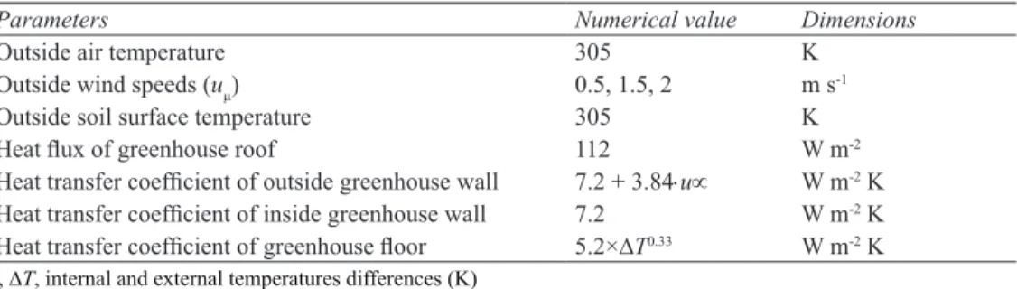
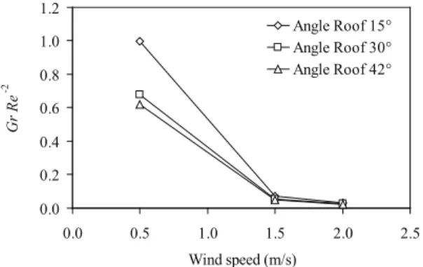
Şekil


Benzer Belgeler
Sadâret, Dahiliye ve Hariciye Nezâretleri gibi, Bâb-ı Â lî'nin önemli dairelerinin milyonlara varan son dönem Osmanlı evrakını süratle tasnife tâbi tutmak;
Keywords : Analytical method, Immediate roof, Longwall mining, Numerical modeling, Roof weighting
A case of pulmonary metastasis of malignant fibrous histiocytoma with left atrial infiltration via the pulmonary vein. Septic vegetation at the left atrial appendage
Without the help of any other guidance only with the help of OLED display we can able to park manually in the parking areas. So this system will help the people to save
Whereas each of the cooling systems provided lower temperature than the control greenhouse, and also different greenhouses had different internal temperature values, the
In order to demystify the intricate language games and intriguing relationships in the play, the vocabulary provided by Game Theory proves to be helpful.. As Brams emphasizes,
Tazim duruşunu müteakip bir öğrenci Atatürk’ün gençliğe, hita besini okumuş ve bundan sonra, Siyasal Bilgiler Okulundan Mahir Kırbaşlı, gençliğin hislerine
Kendi ken dini geliştirdiği bu dalda şimdiye kadar, hepsi İs tanbul’da olmak üzere beş kişisel sergi
