MOTION CONTROL OF QUADROTOR SYSTEM WITH SLIDING-MODE CONTROL (SMC)
Mehmet YILMAZ Master of Science Thesis
Department of Mechatronics Engineering Assoc. Prof. Dr. Turgay TEMEL
T.R
BURSA TECHNICAL UNIVERSITY
GRADUATE SCHOOL OF NATURAL AND
APPLIED SCIENCES
MOTION CONTROL OF QUADROTOR SYSTEM WITH
SLIDING-MODE CONTROL (SMC)
MASTER OF SCIENCE THESIS
Mehmet YILMAZ
Department of Mechatronics Engineering
BURSA January 2015
MASTER OF SCIENCE THESIS EXAMINATION RESULT FORM
The thesis entitled “MOTION CONTROL OF QUADROTOR SYSTEM WITH SLIDING-MODE CONTROL (SMC)” completed by “Mehmet YILMAZ” under supervision of “Assoc. Prof. Dr. Turgay TEMEL” has been reviewed in terms of scope and quality and approved as a thesis for the degree of Master of Science.
Jury Members
Assoc.Prof. Turgay TEMEL …………..
(Bursa Technical University, Department of Mechatronics Engineering)
Prof. Nurettin ACIR …………..
(Bursa Technical University, Department of Electrical-Electronic Engineering)
Asst. Prof. İsmail BÜTÜN …………..
(Bursa Technical University, Department of Mechatronics Engineering)
Date of Examination: 12/01/2015
Director of Graduate School of Natural and Applied Sciences
PLAGIARISM DECLARATION
I hereby declare that all information in this document has been obtained and presented in accordance with academic rules and ethical conduct. I also declare that, as required by these rules and conduct, I have fully cited and referenced all material and results that are not original to this work.
Student Name and Surname: Mehmet YILMAZ
THANKS
Firstly, I offer respect and love to my family because they have brought me up and they always support me.
I offer sincere thanks to my respectable supervisor Assoc. Prof. Dr. Turgay TEMEL because of his major contribution, tolerance, guidance and valuable aids during the master thesis.
I offer sincere thanks to thesis jury members Prof. Dr. Nurettin ACIR and Asst. Prof. Dr. İsmail BÜTÜN because of their tolerance during the thesis defense and helpful feedback after the thesis defense.
I offer love and thanks to my spiritual mother Figen YILMAZ YILDIRIM and her respectable husband Esat YILDIRIM for their financial and moral supports during the my all education life.
v
TABLE OF CONTENTS
Page Outer Cover
Inner Cover
Thesis Examination Result Form Plagiarism Declaration
Thanks
Table of Contents v
List of Figures vii
List of Tables ix
List of Symbols and Acronyms x
Özet xii
Abstract xiii
1. INTRODUCTION 1
2. LITERATURE SURVEY ABOUT QUADROTOR SYSTEMS 2
3. INTRODUCTION TO QUADROTOR SYSTEMS 6
3.1 Working Principle of Quadrotor 6
3.2 Areas of Quadrotor Use 9
3.2.1 Structure construction 9
3.2.2 Observation 10
3.2.3 Transportation 10
3.2.4 Weapon 11
3.2.5 Spying 12
3.3 Mathematical Model of Quadrotor 12
4. HOW TO CONTROL QUADROTOR SYSTEMS 16
4.1 Modeling for Control 16
4.2 Definition of Sliding-Mode Controller (SMC) 18 4.3 Sliding-Mode Controller Design for Quadrotor 19
vi
Page
4.4 Simulation of Quadrotor System 20
5. RESULTS AND PROPOSALS 30
REFERENCES 32
vii
LIST OF FIGURES
Page
Figure 1.1 Overview of quadrotor 1
Figure 3.1 Realization of turning 7
Figure 3.2 Flight motions (a) departure, (b) landing 7 Figure 3.3 Yawing motion (a) counter clockwise yawing,
(b) clockwise yawing 8
Figure 3.4 Rolling motion (a) negative rolling, (b) positive rolling 8 Figure 3.5 Pitching motion (a) negative pitching, (b) positive pitching 9 Figure 3.6 Quadrotor is in structure building 9 Figure 3.7 A quadrotor with observation capability 10 Figure 3.8 A quadrotor with water transportation equipment 11
Figure 3.9 A quadrotor as a weapon 11
Figure 3.10 A spy quadrotor 12
Figure 3.11 The forces which effect quadrotor 13
Figure 4.1 Relation between rotation and translation subsystem 17 Figure 4.2 Block diagram of quadrotor system control 21 Figure 4.3 Block diagram of quadrotor plant 21 Figure 4.4 Block diagram of sliding-mode controller 22 Figure 4.5 Block diagram of angle subsystem 22 Figure 4.6 Block diagram of translation subsystem 23
Figure 4.7 Response for roll angle 24
Figure 4.8 Response for pitch angle 24
Figure 4.9 Response for yaw angle 25
Figure 4.10 Error in roll angle 25
Figure 4.11 Error in pitch angle 26
Figure 4.12 Error in yaw angle 26
Figure 4.13 Overall error of roll angle including disturbance 27 Figure 4.14 Overall error of pitch angle including disturbance 27
viii
Page Figure 4.15 Overall error of yaw angle including disturbance 28 Figure 4.16 Overall error of roll angle including model parameter
variations with varying variances in percent in relative to nominal model
parameters: (a) σ2=0, (b) σ2=1, (c) σ2=2, (d) σ2=3 28 Figure 4.17 Overall error of pitch angle including model parameter
variations with varying variances in percent in relative to nominal model
parameters: (a) σ2=0, (b) σ2=1, (c) σ2=2, (d) σ2=3 29 Figure 4.18 Overall error of yaw angle including model parameter
variations with varying variances in percent in relative to nominal model
ix
LIST OF TABLES
Page
Table 4.1 State-space variables 16
Table 4.2 Variable definitions in state-space 17
x
LIST OF SYMBOLS AND ACRONYMS Symbols Definition
A propeller disk area
b thrust factor
CL thrust coefficient
d drug factor
FNE total force on body
g acceleration due to gravity
Ixx,yy,zz inertia moments
Jr rotor inertia
Jt total rotor inertia seen by motor
l horizontal distance: propeller center to CoG L angular moment m overall mass R rotation matrix Tb body torque Tg gyroscopic torque u motor input U control inputs
V body linear speed ̃ state error
x, y, z position in body coordinate frame
X,Y,Z position in earth coordinate frame pitch angle
yaw angle roll angle
total moment on body
variable constant variable constant
xi
air density
body angular rate motor angular rate propeller angular rate
overall residual propeller angular speed
Acronyms Definition
CAD Computer Aided Design CoG Center of Gravity
DOF Degree of Freedom
GPS Global Positioning System
OS4 Omnidirectional Stationary Flying OUtstretched Robot PD Proportional Derivative
PID Proportional Integral Derivative SISO Single Input Single Output SMC Sliding-Mode Control UAV Unmanned Aerial Vehicle VTOL Vertical Take-Off and Landing
xii
ÖZET
QUADROTORUN KAYAN KİPLİ KONTROL (KKK) İLE HAREKET KONTROLÜ
Mehmet YILMAZ
Bursa Teknik Üniversitesi Fen Bilimleri Enstitüsü
Mekatronik Mühendisliği Ana Bilim Dalı Yüksek Lisans Tezi
Doç. Dr. Turgay TEMEL
Ocak 2015, 35 Sayfa
Bu tezde, doğrusal olmayan sistemlerin kontrolü için kullanılan kayan kipli kontrolcü tasarlamaktayız. Tez çalışması, türetilen kontrolün, eksik uyarımlı sistemlerden biri olan quadrotorlara uygulanması üzerinedir. Quadrotorlar çeşitli uygulamalar ve eğlence, gözlem, arama-kurtarma, taşımacılık gibi kullanım alanlarından dolayı daha önemli hâle gelmektedir. Ayrıca quadrotorlar, kirli, tehlikeli ve ulaşması zor olan yerlerde kullanılmaktadır. Quadrotorların kontrolü dijital ortamda, quadrotor modelinin verilen yörüngeyi izleme yeteneğinin simülasyonu ile gerçekleştirilecektir.
Anahtar Sözcükler: Kayan kipli kontrol, lineer olmayan kontrol, quadrotor, eksik uyarımlı sistemler.
xiii
ABSTRACT
MOTION CONTROL OF QUADROTOR SYSTEM WITH SLIDING-MODE CONTROL (SMC)
Mehmet YILMAZ
Bursa Technical University
Graduate School of Natural and Applied Science
Department of Mechatronics Engineering Program
Master of Science Thesis
Assoc. Prof. Dr. Turgay TEMEL
January 2015, 35 Pages
In this thesis, we investigate sliding-mode controller which is used in nonlinear systems. Thesis resorts on application of the derived control for quadrotor, a class of underactuated systems. Quadrotors are becoming more important for various applications and fields such as environment, observation, search and rescue, transportation. Also they are used in dirty, dangerous and hard to reach places. The motion control of quadrotor will be realized in digital media with simulation of quadrotor model in terms of tracking capability given a target trajectory.
Key Words: Sliding-mode control, nonlinear control, quadrotors, underactuated systems.
1 1. INTRODUCTION
Nowadays, with progress of technology, new scientific branches and studying areas occur. One of these areas is quadrotors. Quadrotors can be in a different design and property. Quadrotors can be used for military, defense and attack. In addition, it provides studying in harmful areas for human area, the area where human does not enter because of hot, cold, dirty, radioactivity, etc.. and the area where human does not reach because of small and tight. These vehicles are moved by user command, also move with autonomous systems like artificial intelligent and fuzzy logic. In this thesis, moving of quadrotor is provided with sliding-mode control (SMC) technique. In this study four rotor quadrotor, in a special name, quadrotor is considered.
2
2. LITERATURE SURVEY ABOUT QUADROTOR SYSTEMS
A quadrotor is designed and constructed which is capable of indoors and outdoors hovering using a mechatronics system by Hussein and others [2]. Using of mechatronics system, stability and navigation aspects are provided using gyros, accelerometers, pressure sensor, and GPS. In this paper, mathematical models are studied, for estimating mass and inertial properties of the physical model a CAD model is built, for estimating the response of flight dynamics a Simulink is implemented and the last, a physical model is built as prototype for the UAV.
The results are presented of two nonlinear control techniques which are applied to an autonomous micro helicopter called Quadrotor by Bouabdallah and Siegwart [3]. A backstepping and sliding-mode controller techniques are used. These controllers are performed as simulation and experimental in open and close loop control. A special call “OS4” test-bench is used in experimental setup.
Altitude stabilization, hovering control and altitude control of quadrotor is studied by Dikmen and others [4]. For nonlinear system, classically PD control, invers dynamic control, backstepping control and sliding-mode control techniques are simulated using mathematical model and applied to quadrotor platform in experimental setup. And the results are compared.
The mathematical model of quadrotor is focused by Elruby and others [5]. To estimate mass and inertial properties of quadrotor‟s physical model, a CAD model is built. Physical model is simulated in Simulink using the mathematical model of quadrotor. PID controller is applied to quadrotor and step response and pulse response are observed.
A feedback linearization-based controller with a high order sliding-mode observer running parallel is applied to quadrotor unmanned aerial vehicle by Benallegue and others [6]. The high order sliding mode observer is worked as an observer and estimator of the effect of the external disturbances such as wind and noise. The whole observer-estimator-control is constituted an original approach to the vehicle regulation with minimal number of sensors. Performance issues of the controller-observer are illustrated in a simulation study that takes into account parameter uncertainties and external disturbances.
3
The final results of the modeling and control parts of OS4 project, which focused on design and control of quadrotor are summarized by Bouabdallah and Siegwart [7]. A simulation model which takes into account the variation of the aerodynamical coefficients due to vehicle motion is introduced. The control parameters found with this model are used on the helicopter without re-turning. Integral Backstepping control approach are described and proposed for full control of quadrotors (attitude, altitude and position). The results of autonomous take-off, hover, landing and collision avoidance are presented.
A model of a four rotor vertical take-off landing (VTOL) unmanned air vehicle known as quadrotor aircraft is presented by Erginer and Altuğ [8]. The quadrotors mathematical model is built and it is simulated in MatlabTM [1]. PD controller is applied to quadrotor. The control architecture of quadrotor including vision based control is explained.
The development of an autonomous four-rotor Rotary-wing Unmanned Mini Aerial Vehicle (RUMAV), called Quadrotor is presented by Goel and others [9]. Quadrotor‟s modeling, simulation and control design is implemented and the results from flight experiments conducted on a flying platform are presented. PID controller is used as control law. The control algorithm is validated using simulations and 3D visualization and it is implemented on hardware and experiments on a test-rig and in free flight are conducted.
The X-4 Flyer, a quadrotor robot using custom-built chassis and avionics with off-the-shelf motors and batteries, to be a highly reliable experimental platform is developed by Pounds and others [10]. In order to stabilize flight, tuned flight dynamics are used with an onboard embedded controller. A linear SISO controller is designed to regulate flyer attitude and it is simulated in Simulink.
A mathematical model of quadrotor dynamics are proposed by Amir and Abbass [11]. A simplified approach is adopted using momentum theory. To make it easy and useful for designing a controller of machine, gyroscopic effect and air friction on frame of machine is neglected. Because of the rotor dynamics are a function of square of motor inputs, proposed model is nonlinear.
1
4
Quadrotor airship is modeled and simulated using backstepping control algorithm by Li and Wang [12]. Firstly, kinematic model is established according to Newtonian mechanics. The quadrotor system is divided into two subsystems. The outer loop position controller included position and velocity; the inner loop position controller included body angular velocity, Euler angular velocity and Euler angles. The quadrotor system is simulated in Matlab-Simulink and PID controller method is used as controller. Because of the weakness of using PID controller in nonlinear systems, backstepping algorithm and Lyapunov stability theorem are used to design the controller. Whole system is divided into two return circuits and each circuit are divided into three second order systems which reduce order number of controller effectively.
In their paper, the complete nonlinear modeling of dynamical quadrotor is studied by Ghazbi and others [13]. The modeling is conducted in two parts of body modeling using Newton-Euler‟s method and propulsion system modeling. The propulsion system is modeled in eight phases of movement. According to the movement phase, the system dynamic is switched on one the models. The completely nonlinear model is simulated in Matlab software. The accuracy of the system is evaluated by designing and implementing six dynamic performance tests on the model and three PD controllers are designed and applied to the system with the aim of controlling the attitudes.
In their paper, a new design method is presented for the flight control of an autonomous quadrotor helicopter based on sliding-mode control by Xu and Özgüner [14]. Due to the under-actuated property of a quadrotor helicopter, the controller can make the helicopter move three positions (x,y,z) and the yaw angle to their desired values and it is stabilized the pitch and roll angles. A sliding mode control is proposed to stabilize a class of cascaded under-actuated systems. The global stability analysis of the closed-loop system is presented. Because of the robustness of the sliding-mode controller, it is preferred.
Four rotor unmanned aerial vehicle‟s (UAV) modeling and control is subjected by Orsag and Bogdan [15]. A popular dynamic model is improved and using PID based classical controller‟s various combinations, a hybrid controller is obtained. Position control in x, y, z axis and control of yaw angle is realized with different controllers.
5
Four rotor unmanned aerial vehicle‟s (UAV) kinematic model is obtained and to control of this model a controller is designed by Morel and Leonessa [16]. Designed nonlinear controller is improved using Lyapunov function.
For a four rotor unmanned aerial vehicle (UAV) nonlinear dynamic model is obtained and for movement of this model a backstepping controller is designed by Madani and Benallegue [17]. Designed nonlinear controller is developed using Lyapunov stability theorem. The control is divided to three subsystem; incomplete propelling subsystem, complete propelling subsystem and propeller subsystem. Designed backstepping controller is simulated and good performance is observed.
In their study, a nonlinear model of an underactuated six degrees of freedom (6 DOF) quadrotor helicopter is derived on the basis of the Newton-Euler formalism by Mian and Daobo [18]. Equations of motion of the quadrotor in three dimensions are derived. The model is parted to translational and rotational subsystems and because of the instability of the subsystems nonlinear control strategy is used. PD controller is used for translational subsystem and a backstepping based PID is used for rotational subsystem. The performances of the nonlinear control method are evaluated by nonlinear simulation.
6
3. INTRODUCTION TO QUADROTOR SYSTEMS
Before using of quadrotors, some air vehicles were used. With invention of quadrotors, they replaced of these air vehicles in many area. Because of this, quadrotors have many advantages:
They have simple mechanics. They have higher payload capacity. They are easily controllable.
They are less effected from gyroscopic effects.
Beside the advantages, quadrotors also have many disadvantages: High-energy consumption.
Higher weight. They have lower payload/weight ratio. They have new, developing technology.
3.1. Working Principle of Quadrotor
Four rotor quadrotor‟s motion is provided with control of the motors which are placed at the endpoints of the body that is like “plus” (+) shape. Here, opposite motors turn the same way and neighbor motors turn opposite way. According to motor‟s velocity values, landing-departure, roll, pitch and yaw motions are carried out.
The motion of quadrotor dependent on about moment which is produced by motors. To produce a moment, the motor speeds are held constant on moment axis. On the other hand, one of the motor‟s speed is reduced and other‟s is increased on moment direction. So, while the thrust force is reduced in one side, the thrust force is increased in other/opposite side. According to below formulation, the thrust force is related with square of velocity.
( ) (3.1)
For example, in Figure 3.1, negative rolling moment is shown. During this motion, while number 2 and 4 motors‟s speed are held constant, number 1 motor‟s speed is decreased and number 3 motor‟s speed is increased.
7
Figure 3.1 Realization of turning [1]
In below figures, motors‟s turning ways are shown and turning velocities are shown with different thickness lines. While the thickness is increasing, the velocity increases. In Figure 3.2 the motors turn with same velocity. In Figure 3.2 (a), the departure motion occurs because of higher motor speeds, in Figure 3.2 (b), the landing motion occurs because of lower motor speeds.
8
In Figure 3.3, yawing motion is shown. Yawing moment occurs around quadrotor‟s vertical axis. The yaw moment occurs in opposite direction of faster motors‟s direction.
Figure 3.3 Yawing motion (a) counter clockwise yawing, (b) clockwise yawing [1] In Figure 3.4 rolling motion is shown. Rolling motion occurs around the longitudinal axis. While the quadrotor is rolling in counter clockwise direction, the left side motor‟s velocity is reduced and the right side motor‟s velocity is increased. For opposite direction motion, the opposite processes should be done.
Figure 3.4 Rolling motion (a) negative rolling, (b) positive rolling [1]
In Figure 3.5 pitching motion is shown. This motion occurs around of lateral axis. Like as yawing and rolling motion, the moment is produced. For positive pitching motion, so going up of quadrotor‟s noise and going down of quadrotor‟s tail, the front motor‟s velocity is increased and behind motor‟s velocity is decreased. For
9
opposite direction motion, so negative pitching motion, the motor speeds are changed.
Figure 3.5 Pitching motion (a) negative pitching, (b) positive pitching [1] 3.2. Areas of Quadrotor Use
3.2.1. Structure construction
Quadrotors can be used in structure construction with remote control or autonomous control like shown in Figure 3.6. When many quadrotor is used with autonomous control, desired work can be ended in a short time.
10 3.2.2. Observation
With assembly of a camera to quadrotor, individual and military observation can be done. In Figure 3.7, an observer quadrotor is shown.
Figure 3.7 A quadrotor with observation capability [1] 3.2.3. Transportation
By increasing the size of quadrotor, it can be used many in areas. Like seen in the Figure 3.7, quadrotor transports the water tank. With transportation of water by quadrotor rapidly, the fire can be put out easily.
Nowadays, in any health problem, with transportation of first aid equipment with quadrotors rapidly, the emergency intervention is provided to people.
11
Figure 3.8 A quadrotor with water transportation equipment [1] 3.2.4. Weapon
Nowadays, the aerial attacks are made more than land attacks so quadrotors will be useful in this field. The quadrotors which are remote or autonomous controlled and have high maneuver capability are used as a weapon in order to attack certain targets as shown in Figure 3.9.
12 3.2.5. Spying
Actually, this section is not independent from “attack” or “observation” tags. Difference of this scenario, quadrotor does not leave trace after spying, it eliminates own self.
Spy quadrotor‟s body/chassis is made from biological material as shown in Figure 3.10, the vegetative part of fungi, mycelium. In any unexpected state, when it is understood it will be caught, the quadrotor leaves own self to creek or puddle, so it eliminates own self.
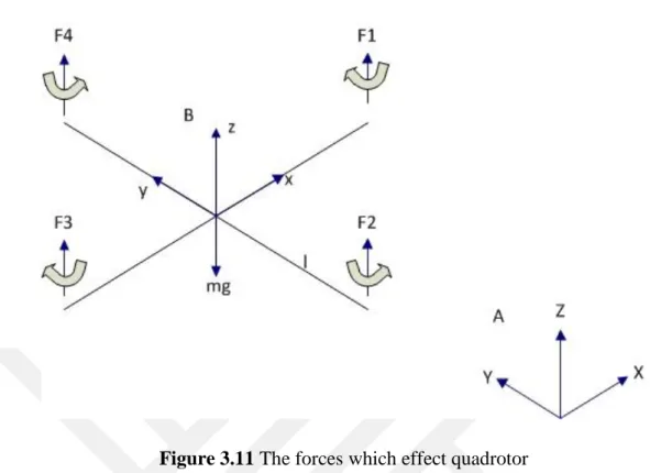
Figure 3.10 A spy quadrotor [19] 3.3. Mathematical Model of Quadrotor
In this section, quadrotor‟s mathematical equations are obtained using Newton-Euler method. While the mathematical model is developed, some assumptions are considered [20]:
The structure is supposed to be rigid.
The structure is supposed to be symmetrical.
The CoG and the body fixed frame origin are assumed to coincide. The propellers are supposed to be rigid.
Thrust and drag are proportional to the square of propeller‟s speed. There is no air friction on quadrotor body.
Free stream air velocity is zero.
In Figure 3.11, earth fixed-frame is represented with A and body fixed-frame represented with B.
13
Figure 3.11 The forces which effect quadrotor
Mathematical model‟s equations are obtained from, Bouabdallah S., Siegwart R.‟s [7] and Kırlı A.‟s [21] works. Using Euler angles notation, rotation matrix is defined as below,
*
+ (3.2)
where cosine is represented with “c” and sine is represented with “s”.2
The dynamics of a rigid body under external forces applied to the center of mass and expressed in the body fixed frame are represented in Newton-Euler formalism as:
* + [
̇
̇
] *
+ [ ] (3.3)
where quadrotor‟s inertia matrix is represented with , body linear velocity
vector is represented with V, body angular velocity vector is represented with , the total force that effect the body is represented with , the total moment on body is represented with and the quadrotor‟s mass is represented with m.
Total thrust force is represented as, 2
14
∑ (3.4)
where the each motor‟s angular velocity is represented with and the thrust coefficient is represented with b. So, the acceleration is represented in vertical direction as,
(3.5)
While the effect of acceleration to earth fixed-frame A is being represented as
, and the gravity is g, so that the acceleration equation in vertical direction is
defined as,
(3.6)
When that equation is solved, the translational motion equations are obtained:
̈ (3.7) ̈ (3.8)
̈ (3.9)
The moments of inertia in x, y and z axes can be defined as,
*
+ (3.10)
So, the angular momentums in x, y and z axes can be defined as,
(3.11)
Hence, the torque of quadrotor body is represented as,
̇ (3.12)
̇ (3.13)
The gyroscopic torque which becomes because of turning motion of propeller, can be defined as,
∑ (3.14)
The quadrotor‟s rotors produce the thrust forces. These forces cause the moments. Using these moments quadrotor‟s motion is provided. l represents the quadrotor‟s one shaft‟s tall, half of it‟s represents the moment arm. Here, b represents the thrust factor and d represents the drag factor, so, the torques are defined as,
15 * + (3.15)
So, the torque equation is represented as,
(3.16)
When the torque and acceleration equations are banded together, the rotation motion equations are obtained:
∬ ( ̇ ̇ ( ) ̇ ) (3.17) ∬ ( ̇ ̇ ( ) ̇ ) (3.18) ∬ ( ̇ ̇ ( ) ̇ ̇ ̇ ̇ ) (3.19)
While the Ui are inputs, the total thrust force is represented with U1, the rolling
moment is represented with U2, the pitching moment is represented with U3 and the
yawing moment is represented with U4. Overall residual propeller angular speed is
represented with .
(3.20)
(3.21)
(3.22)
(3.23)
When the equations (3.20) – (3.23) are rewritten into the (3.7) - (3.9) and (3.17)-(3.19), the position equations are obtained.
∬ (3.24) ∬ (3.25) ∬ (3.26) ∬ ( ̇ ̇ ( ) ̇ ) (3.27) ∬ ( ̇ ̇ ( ) ̇ ) (3.28) ∬ ( ̇ ̇ ( ) ̇ ) (3.29)
16
4. HOW TO CONTROL QUADROTOR SYSTEMS 4.1. Modeling for Control
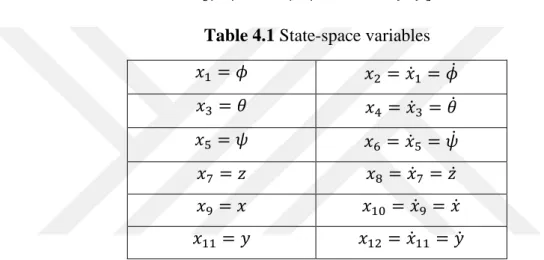
The equations of motions were obtained in (3.24) – (3.29). In order to simplify the model, hub forces and rolling moments are neglected. Also, thrust and drag coefficients are taken constant. Thus, the quadrotor system can be written in state space form ̇ where and are the state and input vectors, respectively. Description and dynamics of the state vector are given in (4.1) and Table 4.1, respectively, while input vector was given in equations (3.20) – (3.23).
̇ ̇ ̇ ̇ ̇ ̇ (4.1)
Table 4.1 State-space variables
̇ ̇ ̇ ̇ ̇ ̇ ̇ ̇ ̇ ̇ ̇ ̇
For small position variation, orientation angles can be considered the same as body angular velocities, ( ̇ ̇ ̇) After some manipulation following equations is obtained, ( ̇ ̇ ̇ ̇ ̇ ̇ ̇ ̇ ̇ ̇ ̇ ̇ ̇ ̇ ) (4.2)
17 together with Table 4.2
Table 4.2 Variable definitions in state-space ( ) ⁄ ⁄ ⁄ ⁄ ⁄ ⁄ where (4.3) (4.4)
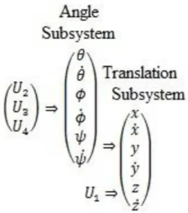
Like quadrotors, robotic systems can be studied as two subsystems: Rotational motion is studied in angle subsystem while translational motion is studied in translational subsystem. Here, as shown in Figure 4.1, the critical point is the fact that the angle subsystem does not depend on translational subsystem but translational subsystem depends on angle subsystem.
18
4.2. Definition of Sliding-Mode Controller (SMC)
In control theory, sliding mode control, or SMC, is a nonlinear control method that alters the dynamics of a nonlinear system by application of a discontinuous control signal that forces the system to “slide” along a cross-section of the system‟s normal behavior. It can switch from one continuous structure to another based on the current position in the state space. Hence, sliding mode control is a variable structure control method. Despite the multiple control structures which are designed so that trajectories always move toward an adjacent region with a different control structure, system states will slide along the boundaries of the control structures. The motion of the system as it slides along these boundaries is called a sliding mode and the geometrical locus consisting of the boundaries is called the sliding (hyper) surface.
Sliding mode control (SMC) is a robust control method. It is not affected by disturbances and system parameter changes.
As a common example, it is considered a second order system [22],
̈ (4.5)
where f(X, t) is generally nonlinear and/or time varying and is estimated as ̂ is the control input while X (t) is the state to be controlled so that it follows a desired trajectory . The estimation error on f(X, t) is assumed to be bounded by some known function F = F(X, t).So that,
| ̂ | (4.6)
For the system dynamics in (4.5), sliding manifold is designed as follows,
( ) ̃ (4.7)
with
̃̇ ̃ (4.8)
19 As a result, controller is given by
̃ ̈ ̃̇ (4.9)
4.3. Sliding-Mode Controller (SMC) Design for Quadrotor
In this study, angular position of a quadrotor is controlled. For this purpose, the following state-space representation is taken into account.
Table 4.3 Angular part of state space
̇ ̇ ̇ ̇ ̇ ̇ ( ̇ ̇ ̇ ̇ ̇ ̇ ̇ ̇ ̇ ̇ ̇ ) (4.10)
The system should be forced to follow the desired trajectory. Firstly, the tracking error is considered,
(4.11)
Then, Lyapunov theorem is used to guarantee convergence and stability. Using Lyapunov theorem, the error is driven to respective origin for each coordinate or state variable of interest. We consider a positive definite and its time derivative being semi-definite negative,
(4.12)
̇ ̇ (4.13) The stabilization of is obtained by introducing a virtual control input ,
̇ (4.14) A sliding manifold is designed as below,
20
̇ (4.15) Similarly, the Lyapunov function is considered for both ,
(4.16)
, the sliding manifold convergence dynamics is satisfied with ̇ | |. ̇
̇ ̈ ̇
̈ (4.17) where and are nonnegative adaptivity constants and „sign‟ refers to „signum function‟. As a result, the control law for is attained as
(4.18) With adoption of similar arguments above respective control laws for and are obtained as follows: (4.19) (4.20) with ̇ (4.21) ̇
4.4. Simulation of Quadrotor Controller
Quadrotor system‟s control model derived above is transformed into digital media and simulated in Matlab-Simulink environment as depicted in Figure 4.2.
21
Figure 4.2 Block diagram of quadrotor system control
Quadrotor system is modelled as a plant shown in Figure 4.3 while the sliding-mode controller designed is shown in Figure 4.4.
22
Figure 4.4 Block diagram of the designed sliding-mode controller
Sliding-mode controller block diagrams are modeled in quadrotor‟s state-space model. Quadrotor plant is modelled in two subsystems; angle subsystem shown in Figure 4.5 and translation subsystem shown in Figure 4.6. In this thesis, angular motion of quadrotor is considered with some blocks painted for emphasis.
23
Figure 4.6 Block diagram of translation subsystem
While realizing control for the quadrotor studied, input for each coordinate, i.e. the anles Phi, Theta and Psi, is varied relative to nominal control obtained previously while other control terms such as gains etc. are adjusted accordingly. Then, each control law is given
̂ (4.22)
where the normalized nominal control and additional control terms are represented by ̂ and , respectively. The nominal control term is obtained at nominal model for a given trajectory, i.e. no statistical error involved provided in [3]. On the other hand, is utilized to remedy external disturbance and other modelling discrepancies. In following, for each coordinate, the response for the normalized nominal control applied at time t =1 sec is calculated and plotted for respective target trajectory. Figure 4.7, 8, and 9 depict the observed responses for roll, pitch and yaw angles, respectively, where they are desired to vary from 0 to 1 radian while the respective control is varied from zero to nominal control at t = 1 sec in no external and modelling error conditions.
24
Figure 4.7 Response for roll angle
25
Figure 4.9 Response for yaw angle
Simulation results reveal that the applied control leads to zero overshoot, zero steady-state error and small rising time in all coordinates. In Figure 4.10, 11, and 12, the error in each coordinate is shown. It is seen that until the first second, quadrotor does not move. Upon application of the control, it starts moving toward the desired position in a short time.
26
Figure 4.11 Error in pitch angle
Figure 4.12 Error in yaw angle
Since the number of actuators for the quadrotor in this thesis is less than the degree of freedom of the system, the quadrotor studied is an underactuted system. Sliding-mode controller is a favorable choice to control such systems due to adaptivity, robustness and fast response, [3]. Above simulation results demonstrate that chosen controller provides fast response with small rising-time and overshoot. In order to demonstrate the robustness and adaptivity characteristics of the SMC, external disturbances shown in Figure 4.2 and parametric randomness shown in Figure 4.5 are
27
activated. Firstly, a disturbance is applied to the quadrotor at each angular motion at
t=3 sec against varying percent ratio of the normalized nominal control calculated,
which is denoted by k. Against to applied disturbances, errors in roll, pitch and yaw motions are shown in Figure 4.13, 14 and 15, respectively. It should be noted that since roll and pitch motions are the similar motions, almost the same errors are observed for these two, which is subject to how quadrotor motion is defined, i.e. like head-tail or tail-head.
In Figure 4.13, external disturbance error of rolling motion is shown.
Figure 4.13 Overall error of roll angle including disturbance
28
Figure 4.15 Overall error of yaw angle including disturbance
In order to demonstrate the robustness of SMC against parametric randomness in modeling we assumed random model variations relative to nominal model parameters in angle subsystem of the quadrotor studied. We considered relative normal random variations with zero mean with varying variances (σ2) in percent. Against to applied disturbances, errors in roll, pitch and yaw motions are shown in Figure 4.16, 17 and 18, respectively.
Figure 4.16 Overall error of roll angle including model parameter variations with varying variances in percent in relative to nominal model parameters: (a) σ2=0, (b) σ2=1, (c) σ2
29
Figure 4.17 Overall error of pitch angle including model parameter variations with varying variances in percent in relative to nominal model parameters: (a) σ2=0, (b) σ2=1, (c) σ2=2, (d) σ2
=3
Figure 4.18 Overall error of yaw angle including model parameter variations with varying variances in percent in relative to nominal model parameters: (a) σ2=0, (b) σ2=1, (c) σ2=2, (d) σ2
30 5. RESULTS AND PROPOSALS
In this thesis, motion control of quadrotor system with sliding-mode control (SMC) is realized. Quadrotor is a mechatronic system which is combined of mechanical, electrical and software disciplines. In thesis, quadrotor is preferred as mechatronic system.
Controlling of quadrotor is realized in Matlab-Simulink with block diagrams. Using with obtained mathematical model of quadrotor, block diagrams are placed in Simulink and quadrotor position control is simulated. Here, quadrotor is examined as two subsystems; angle subsystem and translation subsystem. In this thesis, angle subsystem, rolling, pitching and yawing motions are considered.
In order to control the quadrotor, sliding-mode controller (SMC) is used. One of the choosing reason of SMC, it is useful for underactuated systems. Quadrotor is an underactuated system so, actuator number of quadrotor is less than degree of freedom number of quadrotor. Quadrotor has 4 actuator (rotor) but it has 6 degree of freedom.
SMC is more useful than other controllers like PID. As seen in simulations, SMC provides the zero overshoot, zero steady-state error, little rising time (quick response). Also, SMC is a robust controller. Robust mean, SMC is not affected from external disturbances (i.e. wind for quadrotor) and parametric disturbances/changes (i.e. temperature changing). As seen in simulations, when a disturbance is applied to quadrotor, until a particular threshold value (depends on system variables) quadrotor is not affected from disturbance. It is seen in some studies that if it were studied with PID controller, that threshold value would be lower than SMC.
In this thesis, control of quadrotor is realized in digital media and one of the control method (SMC) is used to control the quadrotor. Besides, disturbance responses of quadrotor which is not studied before.
As a future work, control of quadrotor can be realized with other control methods like backstepping, fuzzy logic, etc… and the results of these would be compared to SMC. Besides, the control of quadrotor can be realized with physical model. Mostly, getting same results are hard from simulation and physical model. In physical model studies, quadrotor can be examined with fixed place test bench or flying. In fixed place test bench studies, computers are used as controller. Communication of
31
computer and test bench is provided with data acquisition cards. In flying studies, with using of sensors, especially cameras which are on quadrotor or in flying area, accelerometer and GPS, different missions (i.e. transportation) and controls are realized.
32 REFERENCES
[1] Yılmaz M., 4 Rotorlu Hava Aracının Motor Kontrolü, Lisans Bitirme Tezi, Yıldız Teknik Üniversitesi-Mekatronik Mühendisliği, İstanbul, 2013.
[2] Hussein W.M., El-khatib M.M., Elruby A.Y., Haleem H.M.,Quadrotor Design, Simulation and Implementation, The International Conference on Computer Science
from Algorithms to Application, 2009.
[3] Bouabdallah S., Siegwart R., Backstepping and Sliding-mode Techniques Applied to an Indoor Micro Quadrotor, IEEE International Conference on Robotics
and Automation, 2005, 2259.
[4] Dikmen İ.C., Arısoy A., Temeltaş H., Dikey İniş-Kalkış Yapabilen Dört Rotorlu Hava Aracının(Quadrotor) Uçuş Kontrolü, Havacılık ve Uzay Teknolojileri Dergisi, 2010, 4, 33.
[5] Elruby A.Y., El-khatib M.M., El-Amary N.H., Hashad A.I., Dynamic Modelling and Control of Quadrotor Vehicle, The 5th International Conference on Applied Mechanics and Mechanical Engineering, 2012.
[6] Benallegue A., Mokhtari A., Fridman L., Feedback Linearization and High Order Sliding Mode Observer For A Quadrotor UAV, International Workshop on Variable
Structure Systems, 2006, 365.
[7] Bouabdallah S., Siegwart R., Full Control of a Quadrotor, IEEE International
Conference on Intelligent Robots and Systems, 2007, 153.
[8] Erginer B., Altuğ E., Modeling and PD Control of a Quadrotor VTOL Vehicle,
IEEE Intelligent Vehicles Symposium, 2007, 894.
[9] Goel R., Shah S.M., Gupta N.K., Ananthkrishnan N., Modeling, Simulation and Flight Testing of an Autonomous Quadrotor, ICEAE, 2009.
[10] Pounds P., Mahony R., Corke P., Modelling and Control of a Quad-Rotor Robot.
[11] Amir M.Y., Abbass V., Modeling of Quadrotor Helicopter Dynamics,
International Conference on Smart Manufacturing Application, 2008, 100.
[12] Li Y., Wang G., Quad-Rotor Airship Modeling and Simulation Based on Backstepping Control, International Journal of Control and Automation, 2013, 369. [13] Ghazbi S.N., Akbari A.A., Gharib M.R., Quadrotor: Full Dynamic Modeling, Nonlinear Simulation and Control of Attitudes, 2014, 759.
[14] Xu R., Özgüner Ü. Sliding Mode Control of a Quadrotor Helicopter, IEEE
Conference on Decision & Control, 2006, 4957.
[15] Orsag M., Bogdan S., Hybrid Control of Quadrotor, 17th Mediterranean
Conference on Control and Aytomation, 2009.
[16] Morel Y., Leonessa A., Direct Adaptive Control of Quadrotor Aerial Vehicles,
33
[17] Madani T., Benallegue A., Backstepping Control of a Quadrotor Helicopter,
IEEE/RSJ International Conference on Intelligent Robots and Systems, 2006.
[18] Mian A.A., Daobo W., Modeling and Backstepping-based Nonlinear Control Strategy for a 6 DOF Quadrotor Helicopter, Chinese Journal of Aeronautics, 2008. [19] http://www.newscientist.com/data/images/ns/cms/mg22429952.400/mg2242995 2.400-1_300.jpg, January 2015.
[20] Bouabdallah S., Design And Control Of Quadrotors With Application to
Autonomous Flying, Phd Thesis, ́cole Polytechnique F ́d ́rale De Lausanne, 2007.
[21] Kırlı A., İnsansız Dört Rotorlu Hava Araçları İçin Değişken Serbestlik Derecli
Yere Sabit Deney Düzeneği ve Denetleyici Tasarımı, İstanbul Teknik
Üniversitesi-Fen Bilimleri Enstitüsü, İstanbul, 2010.
[22] Slotine J.J. E. and Li W., Applied Nonlinear Control, Wenzel J. (Editor), 276-283, Prentice-Hall Inc., New Jersey, 1991.
34 RESUME
PERSONEL INFORMATION
Name and Surname : Mehmet YILMAZ
Birth Date and Place : 25.05.1991 - ORHANELİ Foreign Language : English
E-mail : [email protected]
EDUCATIONAL STATUS
Degree Department University Name Graduation Year Bachelor Science Mechatronics Engineering Yıldız Technical University 2013
WORK EXPERIENCE
Year Firm/Corporation Mission
2010 Aneles Group, Aneles Intern
2012 Delphi Automotive Systems Intern
2012 Karsan Automotive Intern
SCIENTIFIC STUDIES Project
1. “Maximum Metric in R2”, Intel ISEF (International Science and Engineering Fair), USA, 2008.
2. d-QUAKE (Satellite System For Earthquake Detection) – the 2nd Mission Idea Contest for Micro/Nano-satellite Utilization, 2012.
35 AWARDS
1. TÜBİTAK High-School Students Researching Projects Competition Math Branch 1. Place in Turkey, 2007.
2. Star‟s of Bursa, 2007.
3. TÜBİTAK Industry Focused Bachelor Science Graduation Project Support, 2013.
![Figure 1.1 Overview of quadrotor [1]](https://thumb-eu.123doks.com/thumbv2/9libnet/4033334.56424/15.892.190.755.450.761/figure-overview-of-quadrotor.webp)
![Figure 3.1 Realization of turning [1]](https://thumb-eu.123doks.com/thumbv2/9libnet/4033334.56424/21.892.156.667.121.583/figure-realization-of-turning.webp)
![Figure 3.4 Rolling motion (a) negative rolling, (b) positive rolling [1]](https://thumb-eu.123doks.com/thumbv2/9libnet/4033334.56424/22.892.285.660.695.914/figure-rolling-motion-a-negative-rolling-positive-rolling.webp)
![Figure 3.5 Pitching motion (a) negative pitching, (b) positive pitching [1] 3.2. Areas of Quadrotor Use](https://thumb-eu.123doks.com/thumbv2/9libnet/4033334.56424/23.892.282.667.185.399/figure-pitching-motion-negative-pitching-positive-pitching-quadrotor.webp)
![Figure 3.7 A quadrotor with observation capability [1] 3.2.3. Transportation](https://thumb-eu.123doks.com/thumbv2/9libnet/4033334.56424/24.892.158.735.245.628/figure-quadrotor-observation-capability-transportation.webp)
![Figure 3.8 A quadrotor with water transportation equipment [1] 3.2.4. Weapon](https://thumb-eu.123doks.com/thumbv2/9libnet/4033334.56424/25.892.218.738.107.400/figure-quadrotor-water-transportation-equipment-weapon.webp)
![Figure 3.10 A spy quadrotor [19] 3.3. Mathematical Model of Quadrotor](https://thumb-eu.123doks.com/thumbv2/9libnet/4033334.56424/26.892.161.697.398.661/figure-spy-quadrotor-mathematical-model-quadrotor.webp)