This content has been downloaded from IOPscience. Please scroll down to see the full text.
Download details:
IP Address: 212.174.144.130
This content was downloaded on 04/11/2015 at 11:38
Please note that terms and conditions apply.
The ATLAS TRT end-cap detectors
View the table of contents for this issue, or go to the journal homepage for more 2008 JINST 3 P10003
(http://iopscience.iop.org/1748-0221/3/10/P10003)
2008 JINST 3 P10003
PUBLISHED BYIOP PUBLISHING ANDSISSARECEIVED: July 21, 2008 REVISED: September 11, 2008 ACCEPTED: October 7, 2008 PUBLISHED: October 21, 2008
The ATLAS TRT end-cap detectors
The ATLAS TRT collaboration
E. Abat,a,†T.N. Addy,j T.P.A. Åkesson,mJ. Alison,uF. Anghinolfi,cE. Arik,a,†M. Arik,a G. Atoian,zB. Auerbach,zO.K. Baker,zE. Banas,f S. Baron,cC. Bault,c N. Becerici,a A. Beddall,a,1A.J. Beddall,a,1J. Bendotti,c D.P. Benjamin,gH. Bertelsen,d
A. Bingul,a,1H. Blampey,c A. Bocci,gM. Bochenek,eV.G. Bondarenko,pV. Bychkov,l J. Callahan,kM. Capeáns Garrido,cL. Cardiel Sas,cA. Catinaccio,cS.A. Cetin,a,2 T. Chandler,zR. Chritin,h P. Cwetanski,kM. Dam,d H. Danielsson,cE. Danilevich,v E. David,cJ. Degenhardt,uB. Di Girolamo,cF. Dittus,cN. Dixon,cD. Dobos,c O.B. Dogan,a,† B.A. Dolgoshein,pN. Dressnandt,uC. Driouchi,d W.L. Ebenstein,g P. Eerola,mU. Egede,mK. Egorov,kH. Evans,kP. Farthouat,cO.L. Fedin,v∗
A.J. Fowler,gS. Fratina,uD. Froidevaux,cA. Fry,j P. Gagnon,k I.L. Gavrilenko,o C. Gay,yN. Ghodbane,rJ. Godlewski,cM. Goulette,cI. Gousakov,l N. Grigalashvili,l Y. Grishkevich,qJ. Grognuz,cZ. Hajduk,f M. Hance,uF. Hansen,d J.B. Hansen,d J.D. Hansen,dP.H. Hansen,dG.A. Hare,uA. Harvey Jr.,j C. Hauviller,cA. High,u W. Hulsbergen,cW. Huta,cV. Issakov,zS. Istin,aV. Jain,kG. Jarlskog,mL. Jeanty,y V.A. Kantserov,pB. Kaplan,zA.S. Kapliy,uS. Katounine,vF. Kayumov,oP.T. Keener,u G.D. Kekelidze,l E. Khabarova,lA. Khristachev,v B. Kisielewski,f T.H. Kittelmann,w C. Kline,kE.B. Klinkby,d N.V. Klopov,vB.R. Ko,gT. Koffas,c N.V. Kondratieva,p S.P. Konovalov,oS. Koperny,eH. Korsmo,mS. Kovalenko,vT.Z. Kowalski,e
K. Krüger,cV. Kramarenko,qL.G. Kudin,vA-C. Le Bihan,c B.C. LeGeyt,uK. Levterov,l P. Lichard,c A. Lindahl,dV. Lisan,l S. Lobastov,l A. Loginov,zC.W. Loh,yS. Lokwitz,z M.C. Long,jS. Lucas,cA. Lucotte,iF. Luehring,k B. Lundberg,mR. Mackeprang,d V.P. Maleev,vA. Manara,kM. Mandl,cA.J. Martin,zF.F. Martin,uR. Mashinistov,p G.M. Mayers,uK.W. McFarlane,j V. Mialkovski,l B.M. Mills,yB. Mindur,eV.A. Mitsou,x J.U. Mjörnmark,mS.V. Morozov,pE. Morris,k S.V. Mouraviev,oA.M. Muir,y A. Munar,u A.V. Nadtochi,vS.Y. Nesterov,vF.M. Newcomer,uN. Nikitin,qO. Novgorodova,o E.G. Novodvorski,vH. Ogren,kS.H. Oh,gS.B. Oleshko,vD. Olivito,uJ. Olszowska,f W. Ostrowicz,f M.S. Passmore,cS. Patrichev,vJ. Penwell,k F. Perez-Gomez,c V.D. Peshekhonov,lT.C. Petersen,c R. Petti,bA. Placci,c A. Poblaguev,zX. Pons,c M.J. Price,cO. Røhne,t R.D. Reece,uM.B. Reilly,uC. Rembser,cA. Romaniouk,p D. Rousseau,sD. Rust,kY.F. Ryabov,v V. Ryjov,c M. Söderberg,mA. Savenkov,l J. Saxon,uM. Scandurra,k V.A. Schegelsky,vM.I. Scherzer,uM.P. Schmidt,z,†
2008 JINST 3 P10003
C. Schmitt,c E. Sedykh,vD.M. Seliverstov,vT. Shin,j A. Shmeleva,oS. Sivoklokov,q S.Yu. Smirnov,pL. Smirnova,qO. Smirnova,mP. Smith,k V.V. Sosnovtsev,p
G. Sprachmann,cS. Subramania,kS.I. Suchkov,pV.V. Sulin,oR.R. Szczygiel,f G. Tartarelli,nE. Thomson,uV.O. Tikhomirov,oP. Tipton,zJ.A. Valls Ferrer,x
R. Van Berg,uV.I. Vassilakopoulos,jL. Vassilieva,oP. Wagner,uR. Wall,zC. Wang,g D. Whittington,k H.H. Williams,uA. Zhelezkopand K. Zhukovo
aFaculty of Sciences, Department of Physics, Bogazici University,
TR - 80815 Bebek-Istanbul, Turkey
bBrookhaven National Laboratory, Physics Department,
Bldg. 510A, Upton, NY 11973, United States of America
cCERN, CH - 1211 Geneva 23, Switzerland, Switzerland
dNiels Bohr Institute, University of Copenhagen,
Blegdamsvej 17, DK - 2100 Kobenhavn 0, Denmark
eFaculty of Physics and Applied Computer Science of the AGH-University of Science and
Technology, (FPACS, AGH-UST), al. Mickiewicza 30, PL-30059 Cracow, Poland
fThe Henryk Niewodniczanski Institute of Nuclear Physics, Polish Academy of Sciences, ul.
Radzikowskiego 152, PL - 31342 Krakow, Poland
gDuke University, Department of Physics, Durham, NC 27708, United States of America
hUniversite de Geneve, Section de Physique,
24 rue Ernest Ansermet, CH - 1211 Geneve 4, Switzerland
iLaboratoire de Physique Subatomique et de Cosmologie, CNRS-IN2P3, Universite Joseph
Fourier, INPG, 53 avenue des Martyrs, FR - 38026 Grenoble Cedex, France
jHampton University, Department of Physics, Hampton, VA 23668, United States of America
kIndiana University, Department of Physics, Swain Hall West, Room 117, 727 East Third St.,
Bloomington, IN 47405-7105, United States of America
lJoint Institute for Nuclear Research, JINR Dubna, RU - 141 980 Moscow Region, Russia
mLunds Universitet, Fysiska Institutionen, Box 118, SE - 221 00 Lund, Sweden
nINFN Milano and Università di Milano, Dipartimento di Fisica,
via Celoria 16, IT - 20133 Milano, Italy
oP.N. Lebedev Institute of Physics, Academy of Sciences,
Leninsky pr. 53, RU - 117 924 Moscow, Russia
pMoscow Engineering & Physics Institute (MEPhI),
Kashirskoe Shosse 31, RU - 115409 Moscow, Russia
qLomonosov Moscow State University, Skobeltsyn Institute of Nuclear Physics,
RU - 119 992 Moscow Leninskie gory 1, Russia
rMax Planck Institut fuer Physik,
Postfach 401212, Foehringer Ring 6, DE - 80805 Muenchen, Germany
sLAL, Univ. Paris-Sud, IN2P3/CNRS, Orsay, France
tDepartment of Physics, University of Oslo, Blindern, NO - 0316 Oslo 3, Norway
uUniversity of Pennsylvania, Department of Physics & Astronomy,
209 S. 33rd Street, Philadelphia, PA 19104, United States of America
vPetersburg Nuclear Physics Institute, RU - 188 300 Gatchina, Russia
wUniversity of Pittsburgh, Department of Physics and Astronomy,
3941 O’Hara Street, Pittsburgh, PA 15260, United States of America
xInstituto de Física Corpuscular (IFIC), Centro Mixto UVEG-CSIC, Apdo. 22085, ES-46071
Valencia; Dept. Física At., Mol. y Nuclear, Univ. of Valencia and Instituto de Microelectrónica de Barcelona (IMB-CNM-CSIC), 08193 Bellaterra, Barcelona, Spain
2008 JINST 3 P10003
yUniversity of British Columbia, Dept of Physics,
6224 Agricultural Road, CA - Vancouver, B.C. V6T 1Z1, Canada
zYale University, Department of Physics,
PO Box 208121, New Haven CT, 06520-8121 , United States of America
1Currently at Gaziantep University, Turkey
2Currently at Dogus University, Istanbul
†Deceased
E-mail: [email protected]
ABSTRACT: The ATLAS TRT end-cap is a tracking drift chamber using 245,760 individual tubular drift tubes. It is a part of the TRT tracker which consist of the barrel and two end-caps. The TRT end-caps cover the forward and backward pseudo-rapidity region 1.0 < |η| < 2.0, while the TRT
barrel centralη region|η| < 1.0. The TRT system provides a combination of continuous tracking
with many measurements in individual drift tubes (or straws) and of electron identification based on transition radiation from fibers or foils interleaved between the straws themselves. Along with other two sub-systems, namely the Pixel detector and Semi Conductor Tracker (SCT), the TRT constitutes the ATLAS Inner Detector. This paper describes the recently completed and installed TRT end-cap detectors, their design, assembly, integration and the acceptance tests applied during the construction.
KEYWORDS: Particle tracking detectors; Transition radiation detectors; Large detector systems for particle and astroparticle physics.
2008 JINST 3 P10003
Contents
1. Introduction 2
2. The basic detector unit: the eight plane wheel 4
2.1 Design of an eight plane wheel 5
3. Description of the eight plane wheel components 8
3.1 The carbon fiber rings 8
3.2 The detecting elements: straws-preparation and quality control 10
3.2.1 Straw reinforcement 10
3.2.2 Straw production and quality control 12
3.3 Connecting and insulating straws: high voltage plugs, insulation end plugs and
crimp pins 14
3.3.1 High voltage plugs 14
3.3.2 Insulation end plugs 15
3.3.3 Crimp pins 16
3.3.4 High voltage sleeves 16
3.4 The Wheel End-Cap Board (WEB) 17
3.4.1 Quality assurance for the WEBs 19
3.5 The radiators 21
3.5.1 Selection of materials 21
3.5.2 Radiator types and dimensions 22
3.5.3 Assembly and quality control of the radiators 23 3.6 Sealing the active gas volume: carters, cavaliers and passive WEBs 24
3.7 Aging studies 25
4. Assembly of eight plane wheel 25
4.1 The basic assembly unit: the four plane wheel 26 4.1.1 Assembly of the four plane wheels structure: rings, straws and radiators 26 4.1.2 Gas tightness test of the four plane wheel structure 27
4.1.3 Glueing of the Wheel End-Cap Boards 28
4.1.4 High voltage connection and insertion of wires 29 4.1.5 Sealing of the active gas volume: assembly of third ring, passive WEBs
and carters 31
4.2 Combining two four plane wheels to an eight plane wheel 32
4.2.1 Quality control and wheel passport 33
4.3 Eight plane wheels acceptance tests at CERN 33
4.3.1 Measurement of wheel dimensions 33
4.3.2 Measurement of wire tension 34
2008 JINST 3 P10003
4.3.4 Long term high voltage test 36
4.3.5 Straw straightness measurement 36
5. The end-cap group 43
5.1 Overview on the design of an end-cap group 43
5.2 Assembly and integration 43
5.2.1 Mechanical assembly 43
5.2.2 Mounting and testing of the on-detector electronics 46 5.2.3 Mounting and testing of monitoring sensors 49
6. Services 50
6.1 Distribution of active gas 50
6.2 Electronics cooling 51
6.3 Straw cooling 52
6.3.1 Requirements 52
6.3.2 System tests and validation 52
6.3.3 The pump module 53
6.3.4 The gas renewal module 53
6.3.5 The distribution racks 54
6.3.6 Installation on detector and control racks 54
7. Summary of weights and material distribution 55
8. Performance of end-cap modules at beam tests 56
9. Summary and conclusion 58
A. Summary of acceptance tests 59
B. Fact sheet 62
1. Introduction
The Transition Radiation Tracker (TRT) is one of the three subsystems of the ATLAS central tracker, the Inner Detector [1, 2]. It is designed to operate in a 2 T solenoidal magnetic field and to provide a solid tracking information and particle identification at the design luminosity
L = 1034cm2s−1of the Large Hadron Collider (LHC) with up to 22 overlaying proton collisions in a single bunch crossing of the proton beams each 25 ns. A view of one quadrant of the Inner Detector is shown in figure 1. The three detector technologies are indicated, starting with a Silicon Pixel Detector [3] close to the primary interaction point for identifying secondary vertices, e.g. to tag heavy quarks, then a Semi Conductor Tracker (SCT) [4, 5] for a precise measurement of
2008 JINST 3 P10003
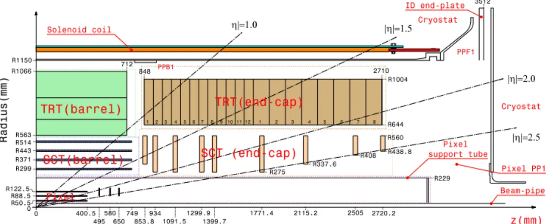
Cryostat PPF1 Cryostat Solenoid coil z(mm) Beam-pipe Pixel support tube SCT (end-cap) TRT(end-cap) 1 2 3 4 5 67 8 9 10 11 12 1 2 3 4 5 6 7 8 Pixel 400.5 495 580 650 749 853.8 934 1091.5 1299.9 1399.7 1771.4 2115.2 2505 2720.2 0 0 R50.5 R88.5 R122.5 R299 R371 R443 R514 R563 R1066 R1150 R229 R560 R438.8 R408 R337.6 R275 R644 R1004 2710 848 712 PPB1 Radius(mm) TRT(barrel) SCT(barrel) Pixel PP1 3512 ID end-plateFigure 1. Plan view of a quarter-section of the ATLAS inner detector showing each of the major detector
ele-ments with its active dimensions and envelopes. The end-cap TRT spans the region from 827<|z|<2744 mm and 617<R<1106 mm in this view, covering a pseudo-rapidity (η) range of 1.0< |η| <2.0.
the tracks transverse momentum perpendicular to the incoming particle beams and finally the TRT occupying the outer region of the cryostat bore.
The TRT section of the tracker is formed from a central TRT barrel Detector [6] with sensor layers parallel to the beam axis1and two (forward and backward) TRT end-caps with their sensor layers radial to the beam axis. The TRT end-caps cover the forward and backwardη region 1.0 < |η| < 2.0. The full length of each end-cap is 1.9 meter, the diameter is about 2.2 meter and the
weight is about 1119 kg.
The TRT end-caps provide both continuous tracking in individual axial drift tubes (or straws) and electron identification using the straws to absorb and to detect transition radiation X-ray pho-tons originating from thin foils between the straw layers. The requirement for the momentum measurement is to contribute to the overall tracking performance by providing a measurement in the R-ϕplane to reach 30µm at luminosity of L= 1033cm2s−1and 50µm at L= 1034cm2s−1[7]. The particle identification is designed to identify clean samples of electrons covering a wide range of particle momenta with a pT between 20 GeV and 40 GeV reaching a rejection factor for charged
pions of about 10. The expected number of transition radiation (TR) photons depends on the length of the track inside the TRT, e.g. for an electron with a momentum of 40 GeV about 11 TR photons are expected at |η| ∼1.7 and 5 TR photons for an electron passing the detector at |η| ∼2.0. On
average about eight transition radiation (TR) photons are expected for an electron at 40GeV. This paper gives an overview of the design, construction and assembly of the TRT end-cap detectors and it is organised as follows. In section 2, the design of the basic detector unit, the so-called eight plane wheel is discussed. Section 3 lists all elements of the eight plane wheel and 1The ATLAS coordinate system is a right-handed system in which the beam direction defines the z-axis and the x− y plane is transverse to the beam direction. The positive x-axis is defined as pointing from the interaction point to the centre of the LHC ring and the positive y axis is defined as pointing upwards. The side-A of the ATLAS detector is defined as that with the positive z and side-C is that with negative z. The azimuthal angleϕis measured around the beam axis, and the polar angleθ is the angle from the beam axis. The pseudo-rapidity is defined asη≡ −ln (tan (θ2)). The
transverse momentum pTis defined as the momentum of a particle in the x− y plane. A position of any point in the x − y
2008 JINST 3 P10003
describes their design, production, assembly and quality control in detail. In section 4 the assemblysteps of an eight plane wheel are described. Section 5 summarises the stacking and merging of a number of eight plane wheels to a complete end-cap group and the mounting of the on-detector electronics plus the control and monitoring sensors. In section 6 the various service installations to supply the detector with active gas, to cool its electronics and cool the detecting elements are described. Sections 7 and 8 summarise the material distribution and weight of the end-cap detector as built and give a brief overview of the performance test of end-cap modules in various beam tests.
2. The basic detector unit: the eight plane wheel
The TRT end-cap design follows the general features characteristic of any tracking system in a collider experiment of which the most essential is the minimization of the dead area for high mo-mentum particles. Each end-cap has a total of 122,880 drift tubes (or straws) with a fairly uniform occupancy.
The straws form a uniform array in the azimuthal plane perpendicular to the beam axis, with a spacing of about 360768◦ between centers in the ϕ-plane and 8 mm or 15 mm in the z direction. The layout of the straws was designed to optimize the probability of the detection of transition radiation as well as to maximize the number of hits along a track. The straw diameter was chosen to be 4 mm as a reasonable compromise between speed of response, number of ionization clusters, and mechanical and operational stability. The straw anode is 31µm-diameter gold-plated tungsten wire at ground potential and the cathode is the straw wall. The straw is typically operated at a high voltage of -1530 V, corresponding to a gas gain 2.5×10⁴ for the gas mixture 70% Xe, 27% CO
2,
and 3% O2.
The mechanical design of the TRT end-caps must provide high mechanical rigidity and dimen-sional stability with a minimum amount of material and weight. For reasons of efficient construc-tion, handling, testing and transportaconstruc-tion, the end-caps are not built as a single mechanical structure but each end-cap is built up from two types of identical independent modules. The modular design approach reduces risk during assembly, enables distributed production at several assembly sites and sped up the final assembly process because each module could be tested independently.
Along the z-axis in each TRT end-cap there is a total of 160 layers of straws, each layer containing 768 individual straws. The straws are arranged so that every charged particle with a transverse momentum pT >0.5 GeV and with a pseudo-rapidity η between 1.0 < |η| < 2.0
pro-duces hits in 20 to 36 straws and so that the track can be measured with an intrinsic accuracy of
∼30-50µm. Each end-cap detector has a total of 122,880 straw tubes and matching electronics channels.
The independent modules that make up the TRT end-caps are referred to as wheels because of their cylindrical form and radial straws like spokes. Each mechanically independent wheel contains eight planes of straws but the two types, A-type and B-type differ in the z spacing of these planes. In both cases each of these layers contains 768 radially oriented straws of ∼37 cm length with
uniform azimuthal spacing but stepped, layer to layer, inϕ.
In the first type, the so-called A-type wheels which make up the 96 straw layers closest to the interaction point, adjacent straw planes have a clearance of 4 mm in the z-direction. The B-type wheels which make up the remaining 64 layers have a clearance of 11 mm so that tracks at small
2008 JINST 3 P10003
Table 1. TRT end-cap parameters. The minimum (maximum) pseudo-rapidity|ηmin| (|ηmax|) corresponds to
the maximum (minimum) end-cap radius Rmax=1004 mm (Rmin=644 mm) at minimum (maximum) position of the end-cap along z-axis zmin(zmax).
Wheel Number of Layers Straws |ηmin| |ηmax| zmin zmax Mass
type eight plane wheels (mm) (mm) (kg)
A 12 96 73,728 0.77 1.7 848 1710 424
B 8 64 49,152 1.32 2.0 1740 2710 438
Total for end-cap 20 160 122,880 862
θ angles cross approximately the same number of straws as tracks at larger angles. The space between successive straw layers in each wheel is filled with layers of 15µm thick polypropylene radiator foils separated by a polypropylene net.
The number of straws and the coverage inη and z for each set of wheels is listed in table 1. The mass listed in the table is for wheels, with electronics but without external services connected. The total weight of an end-cap including the connected services is∼ 1119 kg [8].
2.1 Design of an eight plane wheel
A cross-section of an eight plane wheel is shown in figure 2. Each eight-plane wheel is assembled from two back-to-back four-plane assembly units or four-plane wheels which contain four layers of radial straws.
The design of the present TRT end-cap is based on experience gained from an earlier design that was developed in the framework of LHC detector R&D (RD6) [9]. In this first design, the basic module had 16 planes. The main experience gained during the R&D programme was that a 16-plane module was too large and that the modularity should be determined by ease of manufac-ture and the ability to test for such aspects as leak-tightness, electrical viability and dimensional integrity at every stage of the construction. For this reason, in the final design, a four-plane module was chosen as the basic construction unit. In itself a four-plane module is a mechanically stable unit, but it is only when two of these four-plane modules are combined to make an eight-plane wheel that an autonomous device (from the point of view of electronics and active gas distribution) is obtained.
The fundamental support elements in the four-plane module are three concentric carbon-fibre reinforced rings. These rings are numbered consecutively with ring 1 the innermost. Rings 1 and 2 are drilled with holes to accept the straws. Ring 3 is solid. The outer structure of the four-plane module has the form of a reinforced beam, consisting of ring 2 and ring 3 linked by lateral elements, so called Wheel End-Cap Boards (see figure 2), connected by ’spokes’ (carbon fibre reinforced straws) to an inner ’hub’ (ring 1 made gas-tight by a Kapton R casing). One of the major
design concerns was to make the structure strong enough to reduce the deformations to the order of a few tenths of a millimetre under the module’s own weight.
To assemble a four plane wheel, straws were inserted and glued into precisely drilled holes in the inner and outer carbon-fiber rings or C-fiber ring. They are glued without any mechanical constraints and have a straightness requirement on the sagitta of less than 300µm.
One of the main innovations of the RD6 prototype, namely the use of carbon fibre reinforced Kapton R straws, was retained in the present TRT end-cap design. As described in section 3.2.2
2008 JINST 3 P10003
Figure 2. Basic layout of eight plane wheel which consist of two back-to-back four plane wheels with the
straw and wire connection at the inner and outer radius. In this figure the inner radius is to the left and the outer is to the right. The layout is shown for type-A wheels and all distances are in mm.
each straw is reinforced with four carbon-fibre filaments running along its length. This reinforce-ment reduces the straw deformation due to temperature and humidity variations and improve elec-trical properties of the straw. However, the outer surface of the reinforced straw is no longer cylindrical and would lead to a challenge in the accurate positioning of the straw and gas tightness of the wheel. In addition the straw wall is kept at high voltage. For both of these reason the straws are equipped with insulated end plugs prior to their insertion into the wheel.
The straws are capable of supporting their own wire tension of 60 g without buckling or sig-nificant deformation. This is an important design feature, since it simplifies the assembly and decreases the risk of observing bent straws in the finally assembled detector. The combination of carbon-fibre reinforced straws and lightweight carbon-fibre rings, gives a mechanical structure with low mass: the support structure for the straws and radiators (ring 1 and ring 2) weighs 0.9 g per straw. This has to be compared to a weight of 0.7 g for a reinforced straw (without end plugs), to which the carbon-fibre strands contribute∼30%.
A complex rigid-flex printed-circuit board, referred as the WEB (Wheel End-Cap Board) pro-vides high voltage and signal connections for the end-cap wheels through two separate flexible layers (figure 3). Each flexible layer, made of polyimide, has conductive paths from a signal or HV connection on the rigid part of the board to holes with six inward-pointing petals that are forced by a plastic plug against the inner wall of the cathode to make the electrical connection to the straw. The WEB petals are shown in figure 4.
The signal (anode) connection is done in an analogous way using a second flexible layer, also containing holes with metallic petals. A press-fit between petals in the signal layer and a metallic crimping pin inserted into the outer end plug positions and electrically connects the anode wires. A copper crimping pin covered by plastic is inserted into inner end plug and fixes the anode wire at the inner radius.
2008 JINST 3 P10003
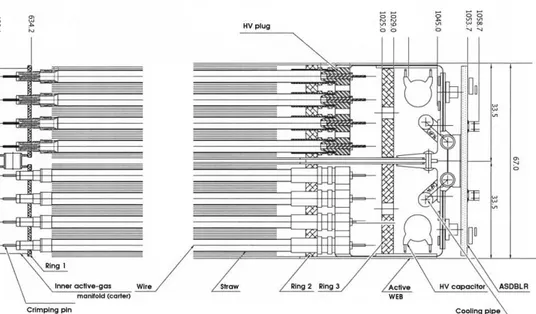
Figure 3. Schematic view of the TRT end-cap
wheels, showing the plastic end plugs used to po-sition and fix the straws in the inner (right side of this figure) and outer (left side of figure) C-fibre rings, the crimping pins holding and positioning the wires, the inner and outer active-gas mani-folds, and the flex-rigid printed-circuit board on the left used to connect the straws to high voltage and the wires to the front-end electronics.
Figure 4. The flexible layers of a Wheel
End-Cap Board (WEB) with the conductive paths for a signal from anode wires to the rigid part of the board. The anode wires are connected to the path via a crimping pins (one seen on the photo) through holes with six inward-pointing petals.
A third C-fibre ring at the outer radius is glued to the rigid part of the flex-rigid printed circuit board and to a simpler glass-fibre board, referred as passive WEB, on the opposite side of the four-plane wheel. This design provides a rigid structure around the outer wheel perimeter that also serves as the outer gas manifold. The inner gas manifold is made from reinforced polyimide material.
Two four-plane wheels are held together as a eight plane wheel through a set of temporary short axial metallic tie-rods at the outer radius and by gluing of input and output connectors of the gas manifolds for the both wheels on the inner radius. The temporary short metallic tie-rods are replaced by permanent long tie-rods during the stacking of the wheels into the final mechanical unit. The whole eight plane wheel is covered with a thin metal-clad polyimide membrane on each r-ϕ side and at the inner radius. The metal cladding of the membrane provides a signal-return path from the inner radius of the straw to the outer radius, where the electronics ground is defined. Additional membranes are used to provide a CO2cooling gas envelope. The cooling gas is required
to remove the heat that is generated in the straws as the positive ions, created by the ionizing particles, drift to the cathode.
The ionization current heat dissipated in the straws is removed through the CO2cooling gas,
which enters each eight plane wheel at its inner radius and then flows out along the straws and radiators foils. The cooling gas itself is cooled in a metallic heat exchanger located at the outer radius between groups of one or two eight plane wheels, and then flows down to the next wheel. The heat dissipation depends directly on the straw counting rate and is estimated to be 10 to 20 mW per straw at the design LHC luminosity. In order to maintain straw operational stability and gas-gain uniformity, the temperature gradient along a straw should not exceed 10◦C. In addition, the flow of CO2evacuates any xenon gas which might leak out of the straws. Xenon in the inter-straw
region could absorb transition radiation photons and degrade the electron identification efficiency of the TRT.
2008 JINST 3 P10003
The assembly of the end-cap modules was performed at two assembly sites in Russia: PNPI [10]and JINR [11].
3. Description of the eight plane wheel components
All components used for TRT end-cap assembly are expected to remain stable over a period of 10 years at ambient temperature (with temperature gradients not larger than 20◦C across TRT end-cap detectors) under the radiation environment expected at the LHC (not more than 10 Mrad integrated dose over 10 years of operation) and exposed to a gas environment composed of CO2, O2and Xe.
3.1 The carbon fiber rings
The TRT cap support rings are the key elements of the mechanical structure of the TRT end-cap wheel. In order to achieve the required overall accuracy together with light weight, the support rings are manufactured in composite materials with specific tolerances of some tens of microns. The choice of material is based upon five criteria: the transparency to particles, the mechanical behaviour, the radiation hardness, the low out gassing and the low gas permeability. On the basis of the above requirements, high performance Carbon Fibre Reinforced Plastic (CFRP) was selected to be used to manufacture the rings. The ring matrix is epoxy resin and the material has the following general properties:
• radiation hardness of resin2≥10 MRad [12];
• circumferential coefficient of thermal expansion (CTE) ≤ 4 · 10−6;
• curing temperature of resin ≤ 120◦C;
• polymerisation degree of resin ≥ 95%;
• the lay-up of fibres is balanced and symmetric for all rings and, in addition, “quasi-isotropic”
for rings A1 and B1 (see table 2).
The radial dimensions, thickness and height of the six different ring types made in CFRP can be found together with other properties in table 2. Each of these rings is perforated by a large number of precise holes (∼3000). The positioning accuracy of the holes is crucial to the
physics performance of the detector. The required tolerances for these holes are: circumferential positioning≤ ±10”and axial positioning≤ ±0.02 mm.
The TRT end-cap rings support the TRT straws. The first ring (A1, B1) or inner support ring at the innermost radius is used to position and fix the straws and is a part of the inner enclosure. The straws are inserted and glued into precisely drilled holes in an inner (A1, B1) and outer (A2, B2) ring. Good mechanical stability of the assembly is ensured at the outermost radius through the beam-like structure formed by the two outer support rings (A2, A3) and (B2, B3) and their flanges (the active and passive WEBs glued to the support rings).
The CFRP rings are electrically conductive and should be at ground potential. Because the rings have a direct capacitance coupling to the signal connectors, it is necessary to make a low
2008 JINST 3 P10003
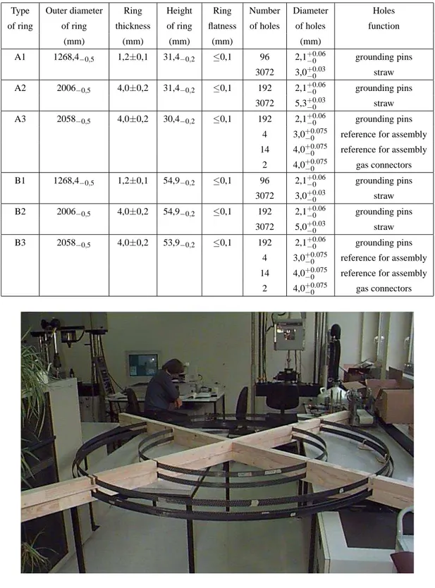
Table 2. Properties of the six TRT end-cap ring types made in Carbon Fibre Reinforced Plastics (CFRP).
Type Outer diameter Ring Height Ring Number Diameter Holes of ring of ring thickness of ring flatness of holes of holes function
(mm) (mm) (mm) (mm) (mm) A1 1268,4−0,5 1,2±0,1 31,4−0,2 ≤0,1 96 2,1+0.06−0 grounding pins 3072 3,0+0.03−0 straw A2 2006−0,5 4,0±0,2 31,4−0,2 ≤0,1 192 2,1+0.06−0 grounding pins 3072 5,3+0.03−0 straw A3 2058−0,5 4,0±0,2 30,4−0,2 ≤0,1 192 2,1+0.06−0 grounding pins
4 3,0+0.075−0 reference for assembly 14 4,0+0.075−0 reference for assembly
2 4,0+0.075−0 gas connectors B1 1268,4−0,5 1,2±0,1 54,9−0,2 ≤0,1 96 2,1+0.06−0 grounding pins 3072 3,0+0.03−0 straw B2 2006−0,5 4,0±0,2 54,9−0,2 ≤0,1 192 2,1+0.06−0 grounding pins 3072 5,0+0.03−0 straw B3 2058−0,5 4,0±0,2 53,9−0,2 ≤0,1 192 2,1+0.06−0 grounding pins
4 3,0+0.075−0 reference for assembly 14 4,0+0.075−0 reference for assembly
2 4,0+0.075−0 gas connectors
Figure 5. The TRT end-cap rings A1 and A2.
impedance electrical connection between the ring and the detector signal return ground. This con-nection is made by gluing special contact pins into holes drilled in the rings.
2008 JINST 3 P10003
The rings were industrially produced at the Perm “Mashinostroitel” company (Russia) [13].The quality control procedures used are designed to verify conformity to the technical specifi-cations. The contractor has measured all the relevant properties of the ring and guaranteed its conformity before packing for delivery to assembly sites in Russia. The following measurements of each ring were made:
• ring dimensions measurements - the height and the circumferential positioning of the holes,
the real diameter of the holes, the diameter, height and wall thickness of the rings, ring not-flatness;
• ring deflection under load to check the overall mechanical behaviour of each manufactured
ring;
• amount of the fibers and resin in the ring material;
• Young’s module measurements under traction and bending for each ring; • polycondensation value of resin by a extraction method;
• circumferential coefficient of thermal expansion; • visual inspection.
The TRT end-cap support rings delivered to assembly sites passed through Input Quality Con-trol (IQC) procedures at each site. These procedures include the following measurements: ring not-flatness, height of the ring, the ring thickness, hole diameter, ring’s deflection and visual in-spection. The results of the IQC at the assembly sites and the control procedure at the company were used to create a passport for the each ring. The passport was uploaded to the production data base and are accessible through a Web interface.
3.2 The detecting elements: straws-preparation and quality control
The straws are straight thin-walled circular tubes, approximately 70µm thick, with an internal diameter of 4 mm. The straws as produced are 1660 mm long. The design, production and perfor-mance of the straw are described in detail in other documents [14, 15].
A straw is industrially produced [16] by helicoidal winding and bonding together two thin strips of polyimide film coated with aluminum and graphite on one side and polyurethane on the other. The polyimide film is a Kapton R 100VN film, 25± 2.5µm thick. The main challenge was
to obtain a satisfactory final product complying with the stringent mechanical specifications (e.g. the diameter tolerance). A total of about 200,000 straws were manufactured.
3.2.1 Straw reinforcement
The straws as wound are affected by environmental factors, such as humidity and temperature, and can significantly change size or even lose straightness. In order to ensure mechanical stability and rigidity for each individual straw, four carbon fibre strands are impregnated with epoxy resin and bonded along the full length of each straw at 90◦with respect to each other.
2008 JINST 3 P10003
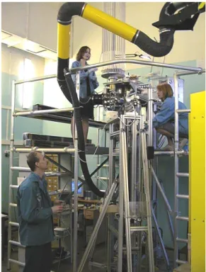
Figure 6. View of Straw Reinforcement Machine at the PNPI assembly site.
The implementation of such a reinforcement procedure for the production of all∼ 200,000
straws has required the design and fabrication of an automated straw reinforcement machine. The operating principle of this machine relies on:
• putting four C-fibre strands of equal length under the same tension; • impregnating them with a known amount of epoxy resin;
• depositing them longitudinally along the outer straw wall; • providing simultaneous polymerization at both ends of the straw.
The Straw Reinforcement Machines (SRM) were designed and constructed at CERN by the technical support (TA1) group. Two SRMs were set up at the assembly sites, one at PNPI and another at JINR. Figure 6 shows the machine at PNPI. A total of∼106,000 straws were reinforced
at PNPI and∼90,000 at JINR from 1999 to 2002.
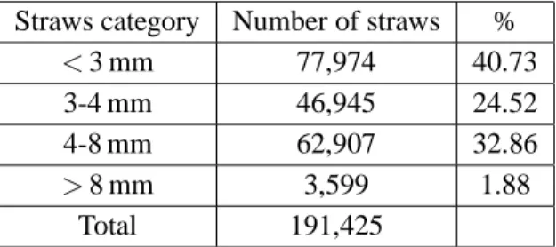
The straw curvature or straightness is an important parameter which was measured for each straw after reinforcement. The straws were categorized into four batches according to their devi-ation from straightness (see table 3). The straws that were more than 8 mm from straight were rejected. A special machine was designed to measure straw straightness. A straw inserted into a centered tool at the top of the machine is rotated around its vertical axis at 30 rpm. The curvature is measured by six photoelectric sensors spaced one mm apart as a maximum deflection from the vertical axis at the bottom of the 1660 mm long straw. One straw could be measured in about 15 seconds. The straws were sorted into bins corresponding to the location of the photo-sensors. After reinforcement, the outer diameter of every straw was measured using a gauge of 25 g with a hole of
2008 JINST 3 P10003
Table 3. Distribution of categories of the straw straightness for all reinforced straws from beginning to end
of production.
Straws category Number of straws %
< 3 mm 77,974 40.73
3-4 mm 46,945 24.52
4-8 mm 62,907 32.86
> 8 mm 3,599 1.88
Total 191,425
4.39+0.01−0 mm diameter. The gauge was required to fall freely under its own weight along the full length of the reinforced straw from the top to bottom with the straw vertical. The diameter of the straw after reinforcement is an especially important parameter for the TRT barrel production as the straw, when inserted into a Barrel, must pass through holes of very tight tolerance (+0.03/ − 0) in
the radiator sheets, dividers, and HV plates [6]. The resulting numbers of reinforced straws which passed all the tests are listed in table 3. The production yield was approximately∼98%.
3.2.2 Straw production and quality control
The 1660 mm long reinforced straws destined for production use in the end-cap were cut into four straws of∼400 mm length. This procedure was called “precutting” as the length is not yet precise
and was chosen only for convenience. Precut straws pass through a test of inner surface conduc-tivity as high voltage distribution and signal propagation along straw depend on its resistance. At that time conductive epoxy is placed around one edge of the straw to provide conductivity between inner and outer surfaces.
After that the plastic end plugs which provide isolation of the straw from support rings, gas distribution into straw, wire fixation and fixation of straw in the support rings were glued to the straw. The final step to get the precise length of the completed straw of 372± 0.1 mm was to cut
the outer end plug.
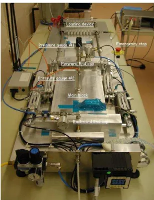
The now fully equipped straw was sent through several quality tests. First it was checked for gas-tightness. Sets of 8 straws were installed into special tooling (figure 7) producing two different gas volumes: one inside the straws, another outside. An overpressure of 1 bar was created inside the straws volume and after 30 seconds of temperature stabilization an increase in the outer volume pressure was observed in case of a straw leak. If the pressure drop inside the straws was more than 0.1 mbar/bar/min, each individual straw was retested to identify the leaking one. This technique was fully automated except for the insertion of the straws into the tooling.
Then the straw was simultaneously checked for straightness and length (figure 8). A CCD camera was moved along a straw that was rotated on its axis. A number of photos were made at different straw rotation angles and at successive points along the straw and analysis of this infor-mation gave the straw straightness value. Measurements of straw length were performed through determination of the position of the straw ends with CCD camera comparing each straw with a standard straw. The criteria for an accepted straw were to have a saggita less then 200µm and a length accuracy better than 100µm. The last step was a visual inspection. During this procedure the operator checked each straw for any damage, bubbles in glued parts, runs of glue etc..
2008 JINST 3 P10003
Figure 7. The machine checking straw
tight-ness. The reached sensitivity was about 0.1 mbar/min/bar. Eight straws were measured simultaneously.
Figure 8. The machine measuring straw
straightness and length.
Straws category Number of straws %
< 100µm 178,809 63.15
100− 200µm 92,939 32.82
200− 300µm 11,418 4.03
Total 283,166
Table 4. Distribution of categories of short straw straightness for all accepted straws produced at both
assembly sites.
Two special workshops were organized at the assembly sites in PNPI and JINR to provide production and testing for short straws. These workshops produced and tested more than 170,000 short straws for A-type wheels and more than 112,000 short straws for the assembly of B-type wheels.3 The production yield was approximately∼ 91%.
Table 4 summarizes the distribution of categories of straw straightness for all accepted straws produced at both assembly sites over the period 2000 to 2004.
3More than 79,000 straws were also produced for C-type wheels. Originally the TRT end-cap was designed with an extension up to|η| <2.5 (|z| <3363 mm) using a third type of wheel, C-type. The C-type wheels were designed to
contain 4608 straws positioned in eight successive layers spaced by 8 mm along z (as for A-type wheels). Each layer, however, contained only 576 straws in the azimuth plane, a lower density and smaller number than for the A and B-type wheels. The straws C-type were also planned to be longer by 14 cm than straws A and B-type to extendη-coverage of the TRT end-cap. The construction of C-type wheels was been staged and have not been assembled.
2008 JINST 3 P10003
Figure 9. Detail of a straw as assembled in the detector.
3.3 Connecting and insulating straws: high voltage plugs, insulation end plugs and crimp pins
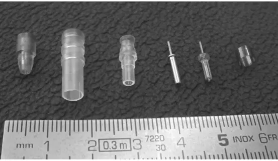
Figure 9 shows a schematic view of the assembly of one straw with the wheel support rings (ring 1 and ring 2). The straw’s connecting elements, three types of end pieces made of precision plastics parts, namely the inner insulation socket, the outer insulation socket and high voltage connector, and the internal anode wire, fastened by crimp tubes on both sides are also visible. In order to achieve the required overall measurement accuracy of the detector the connecting plastic elements had to be manufactured with an accuracy of some tens of microns. A total of about 2,000,000 con-necting elements of five different types were fabricated from the beginning of 2000 to the middle of 2003. Figure 10 is a photo of the various types.
3.3.1 High voltage plugs
The high voltage plugs are custom machined parts that provide a reliable connection from the high voltage to the straw cathode. The high voltage plugs are inserted through the flexible layer of the WEB into the straw, so that the petals of the flexible layer are forced into contact with inner straws walls. The high voltage plugs were manufactured in pure polyetherimide (PEI) [17]. Along the surface of the high voltage plug is a groove with a width and depth of∼0.3 mm which serves as a
2008 JINST 3 P10003
Figure 10. From left to right: high voltage plug, outer and inner end plug, outer and inner crimp pin, and
high voltage sleeve.
3.3.2 Insulation end plugs
Two different sets of precision plastics parts, the outer insulation end plugs and the inner insulation end plugs, were used to connect the ends of the straws to the structure (CFRP rings) of the TRT end-cap wheels. The functions of the end plugs are the following:
• to accurately position and hold the ends of the straws in the support ring (CFRP);
• to precisely locate, to better than 50 microns, the anode wires with respect to the axis of the
straws;
• to ensure absolute stability in time; • to ensure gas tightness;
• to electrically insulate the straws, which are at high voltage (typically 1530 V), from the
wires and the grounded and conductive CFRP rings.
The functionality of the end plugs, during the assembly of the TRT end-caps, relies on a high level of surface finish and on tight dimensional tolerances for the plastic parts. The baseline material selected for the end plugs is Ultem R (General Electric Plastics) [18], an unreinforced
amorphous thermoplastic polyetherimide (PEI), of grades 1000 or 1010. The choice of raw material was based upon the following criteria:
• low viscosity for hard-to-fill parts;
• low interaction cross-section for ionizing particles; • mechanical behavior: stiffness, stability, etc.;
2008 JINST 3 P10003
• radiation hardness;
• low out gassing, low gas permeability; • good adhesive bonding properties;
• good transparency (to allow visual inspection of the glue joints); • high dielectric strength.
All the end plugs were manufactured using injection-molding. For each production batch, 1% of each end plug type was used to carry out verification tests which included a visual as well as geometrical dimension and tolerances check. The delivery was spread from the beginning of 2000 to the middle of 2003.
3.3.3 Crimp pins
The anode wire, a∼ 30µm gold plated tungsten wire is the critical element for the detection of particles. The position and tensioning of the anode wire is ensured by mechanical crimping of small precision (10-20µm ) metal tubes mounted in the two end plugs.
The crimp pins used to fix the anode wire at the ends of the straw were custom designed for the end-cap. The precision metal parts (oxygen free copper - ISO Cu-DHP 99.90) used on the inner radius of the end-cap straws were over-molded with a plastic insulator as shown in figure 10. This inner crimp pin has a purely mechanical function. The outer crimp pin, in addition to the role of positioning the wire, also connects the fast electrical signal to the readout board and is, therefore, electro-plated with gold. In both cases the 30µm anode wire had to thread easily through the pin during assembly.
The crimping pins has a length between 12.5 and 13.3 mm, an outer diameter between 0.7 and 2.5 mm and internal hole diameter of 0.1 mm. For the critical characteristics, such as the outer diameter, inner diameter and concentricity of hollow parts, frequency histograms of the measured values were provided by the supplier.
The delivery of 700,000 crimping pins of two types used to hold the anode wires, was spread over the period 2000–2002.
3.3.4 High voltage sleeves
The straw walls serve as the TRT cathodes and are operated at a voltage of∼1530 V. At the same
time the minimum distance between two adjacent straws on the inner radius is about∼1.2 mm and ∼2 mm between straws and the carbon fiber inner ring which is at ground potential. To decrease
probability of any discharge between two adjacent straws at non equal potentials and between straws and inner ring an additional thin cylindrical ring or HV sleeve was mounted onto the outer straw surface at the inner end (figure 9). The HV sleeves was made from Kapton R by helicoidal
winding and bonding together two thin strips of polyimide film cut to a length of 3.3-3.5 mm. The wall thickness of the HV sleeve is∼ 0.075-1 mm. Internal diameter is ∼ 4.400-4.415 mm, i.e.
2008 JINST 3 P10003
Figure 11. A Wheel End-Cap Board (WEB) for
type A wheels. The main parts of the board, the baseplate containing HV protection capaci-tors (blue elements), HV conneccapaci-tors and fuses (grey elements), the three flaps each containing protection resistors and a connector and finally the two Kapton R flex parts for signal and HV connection can be seen.
Figure 12. Straw high voltage and signal
con-nection scheme. Straws are connected in groups of eight to the HV.
3.4 The Wheel End-Cap Board (WEB)
The active Wheel End-Cap Board (WEB) is the interface between the straws on one side and the readout electronics and high voltage on the other side. The active WEB, an important part of the mechanical and structural framework of the end-cap wheels, is a printed circuit board consisting of two flex Kapton R multi-layers sandwiched between two rigid printed FR-4 [19] boards
(fig-ure 11). A special and innovative design was introduced to minimise the mass of material used in the detector as well as to simplify the assembly procedures for the 250,000 straw channels.
A single board connects 96 straws to their readout channels and supplies three groups of 32 straws with the necessary high voltage (see figure 12).
The size of an individual board is approximately 95×210 mm2 and its main parts are a
base-plate containing HV protection capacitors, HV connectors and fuses, three flaps each containing protection resistors and a connector and finally the two Kapton R flex parts for signal and HV
connection. The lengths of the flex parts are different for A and B type wheels. The active WEB consists of the following main components (figure 13):
• a single sided printed circuit board with a thickness of 0.6 mm and 35µm of copper covered by thin layer of Ni-Au (baseplate);
• a double sided 50µm Kapton R layer with two layers of return signals;
• a single sided Kapton R layer for high voltage distribution;
• a single sided printed circuit board with a thickness of 0.6 mm that serves as shielding.
The baseplate part of the WEB is designed as one of 32 segments inϕ of a circle that forms a seal for the active gas volume between the outermost rings 2 and 3. The high accuracy needed to glue the plates together to make the seal is achieved using three baseplate reference holes which
2008 JINST 3 P10003
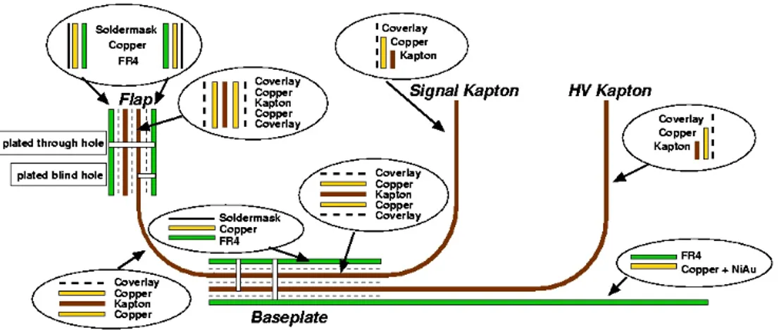
Figure 13. An overview on WEB multi-layer structure. In between the layers of the baseplate and the flaps,
layers of glues are indicated by dashed lines.
were positioned in the assembly jig. On one side, the baseplate is equipped with twelve capacitors of 1 nF to couple the signal return from twelve HV channels of eight straws each to the electronics reference ground. In addition to the capacitors, for each of these groups there is a fuse that can be used to disconnect a HV group in case of some irreparable HV problem (e.g. broken signal wire). The high voltage connection to each group of 96 straws is supplied via three sets of pins and the voltage is distributed to the high voltage flexible Kapton R circuit through 24 blind vias with
a diameter of 1.2 mm. The other side of the baseplate is fully covered by a copper layer which is part of the signal-return path and Faraday shield of the detector. Twelve plated-through holes with a diameter of 300µm connect the ground of the two sides of the plate.
In addition to the custom fuses developed for the TRT, a special device [20] was developed to allow remote manual burning of a fuse using pulses with a voltage of about 1500 V, a frequency 2 kHz and a current of up to 16 mA. Two types of high voltage problems that might call for a fuse to be burned are straws with broken anode wires and straws with a large displacement of the anode wire due to deformation of the straw wall or other parts of the mechanics.
A broken or displaced anode wire can, via repeated discharges, burn a hole in the straw wall which might cause a gas leak. In addition, either type of repeated discharge represents a large source of RF noise that disturbs the sensitive front end electronics throughout the Inner Detector. On the other hand, the fuses should be stable against infrequent single discharges not connected with large displacements. These custom fuses are the result of an extensive research study which took into account temperature, environmental and vibrational effects, stability against radiation damage and the necessary requirement of maintaining a very large fuse resistance after opening. The fuse uses a titanium strip on a lithium niobate plate (LiNbO3). The burning time for the TRT
end-cap fuse is 15-40 ms in the case of an anode-cathode short and 60-200 ms in the case of an anode wire tension loss. In normal conditions it is expected that the HV power supplies would trip early in such a discharge cycle and the manual fuse burning device would be used, after detailed analysis, to open the fuse in the problem area. The leakage current of a burned fuse is less than 10 nA.
2008 JINST 3 P10003
high voltage. The capacitors are rated for 2.5 kV. Long term (2-3 weeks) static tests at 3.125 kVwere performed with all capacitors. Capacitors which developed a short or were showing any sign of leak current were rejected. A subset of the capacitors were tested in a static test of six months. In total about 2% of the tested capacitors failed the tests and were rejected.
A dynamic test was performed on 1% of each batch of capacitors using a series of 500 Hz and voltage of 2.2 kV discharges. There were no failures from this test.
The flaps of the WEB are bent 90◦perpendicular to the baseplate at final installation and carry the anode signals to the ASDBLR electronics board via a connector as shown in figure 2 such that the electronics board are like the tread on the surface of at tyre (see figure 14). The flaps are held in position by non-magnetic screws threaded into an extension of the metallic cooling plates. Near each connector on the flap are mounted 32 protection resistors (24Ω), one for each straw channel, and eight quad protection diodes, one package for a group of four straws (figure 12). In total, 96 plated blind vias with a diameter of 800µm are connected to the rigid part of the flaps to the signal Kapton R. The connector-side of the flaps is connected to the resistors and diodes by 187
plated-through holes with a diameter of 300µm. The smallest trace width and smallest distance between traces on the flaps is about 200µm. To ensure high voltage stability of the board and to avoid any discharge on the WEB surface, the board is covered by a 50µm thick solder-mask except at the locations of solder pads. In addition, after soldering the passive electronic protection elements to the WEB, all boards were cleaned and an additional cover-layer of a urethane conformal coating Fine-L-KoteTM was sprayed on the surface of the baseplate and the flaps.
The two flexible Kapton R layers were introduced to allow a fast but reliable connection from
the anode wires to the electronic readout and from the wall of the straws to the high voltage source. Each flexible layer consists of a main Kapton R layer of 50µm thickness on which the conducting
copper traces for the high voltage or the signal are etched. To protect these traces there is an additional coverlayer of 50µm Kapton R. The signal and high-voltage lines end in “Daisy”-petal
shaped Kapton R-Copper parts of the flex which during the assembly process are squeezed by a
polyetherimide plug to produce an electrical connection. The HV plug is inserted into the straw through the petals to make the high voltage connection. While for the signal connection the “Daisy” petals are pushed into the HV plug by a metal crimp tube which also fixes the signal wire as shown in figure 15. To produce the structure of the “Daisy” petals in the Kapton R film, a novel technique
was developed at and patented by CERN for chemical etching of Kapton R. As the flex Kapton R
connects the four z layers in a sector of a four plane wheel, the WEBs used for type-A wheels have a smaller flex part compared to type-B WEBs where the z spacing between layers is larger.
In order to ensure viability in an LHC detector, the WEBs and all the component materials were tested to be radiation hard up to 10 MRad and up to 1014neutrons/cm2.
The most challenging and demanding tolerances for the fabrication of of the WEBs (especially the reference holes used for assembly) are summarised in table 5.
3.4.1 Quality assurance for the WEBs
In addition to the standard quality control steps at the production company, the reliability and quality of the bare, unstuffed, WEBs were subjected to quality control steps by the collaboration:
2008 JINST 3 P10003
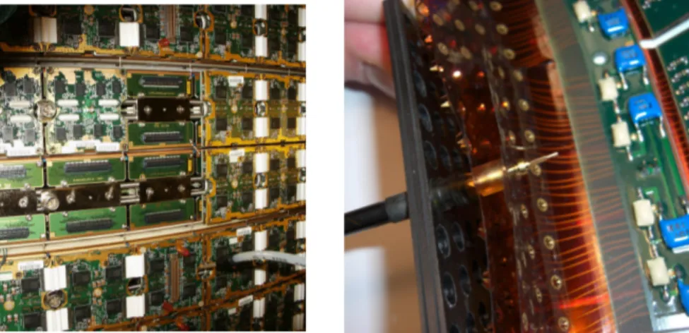
Figure 14. Readout electronics boards on
stacked type A wheels. The bottom and top eight plane wheels are complete with time measur-ing DTMROC triplet boards with their distinc-tive white jumpers. The second and third wheel from the top show some analog ASDBLR boards as well as WEB flex connectors ready for ASD-BLR boards.
Figure 15. Connection of the high voltage and
signal flex of the WEB to the straw end.
Table 5. Mechanical matching tolerances for the WEBs type-A and type-B.
Element Value Tolerance
Angular matching ±10 ”
Diameter of reference holes 3.12 mm +12/0µm Distance between reference holes ±20µm Absolute position of reference holes ±50µm Dimensions of the WEB 95×210 mm +100/0µm
• test of the mechanical stability of the multi-layers: the layers should not break or separate by
applying a force less than 10 kg;
• visual inspection of the flexible layers (no cut, no broken trace, no damaged “Daisy” petals)
and the rigid FR4 part (no broken traces, no cracks);
• for each batch (order of 100 boards), samples were tested to withstand a minimum of 80
bends of±90◦without any visible traces of material fatigue in order ensure robustness of the flexible Kapton R flaps;
• all vias and blind-holes were tested for conductivity and connectivity;
• HV lines (signal lines) had to stand 3000 V (2400 V) w.r.t. ground without measurable current
(< 1 nA)
After the WEBs were equipped with the electronic components — connectors, resistors and diodes — the visual inspection and all conductivity and connectivity tests were repeated. The WEB pro-duction yield was about 60%.
2008 JINST 3 P10003
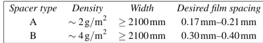
Table 6. Spacer specification for TRT end-cap radiators given to the manufacturer.
Spacer type Density Width Desired film spacing
A ∼ 2 g/m2 ≥ 2100 mm 0.17 mm–0.21 mm
B ∼ 4 g/m2 ≥ 2100 mm 0.30 mm–0.40 mm
After assembly of all wheels into the end-caps the fraction of non-working channels because of WEB defects was less than 0.5%. The remaining defects were largely caused by long term cracking in vias and blind-holes which interrupted and disconnected signal lines. This effect is most likely due to absorption of humidity or cleaning liquid by the Kapton R causing an expansion
of the flexible layers resulting in large mechanical forces. During the end-cap assembly process, vias which showed these problems were repaired and strengthened by inserting a wire through the via and soldering it in place. The number of channels which needed a repair was on the order of one per thousand.
3.5 The radiators
The TRT end-cap radiators are disk-shaped stacks of alternating layers of thin plastic film and sheets of a spacer fabric, and are located in the gaps between adjacent straw planes. In the interest of minimizing material and complexity, no provision was made for stretching the foils to render them perfectly planar, nor to precisely control their spacing. Beam-test measurements had shown that the Transition Radiation (TR) performance of such non-regular foil radiators is close to that of ideal, regular foil radiators [21, 22].
Although entirely made from standard plastic materials, radiation damage is not generally considered a problem for the radiators. Some changes of the material properties under irradiation are assumed to be tolerable, since there should be little or no mechanical stresses in the radiators as mounted in the TRT end-cap wheels.
3.5.1 Selection of materials
Commercially available polypropylene film of 15µm thickness was used for the radiator foils. It was delivered on rolls of 2200 mm width, and was perforated with one 2 mm2hole per 100 cm2of film, in order to allow the finished radiators to breathe easily in response to pressure or composition changes of the environmental gas.
A custom-produced synthetic net (tulle fabric) was used as spacer between successive film layers. The tulle is made from multi-fibre threads composed of 22 dtex4 polyamid fibres. Initial tests had been made with a commercially available tulle fabric used in MLIs.5 It had a mesh size
of 1.4 mm × 1.7 mm, and gave a film spacing of about 180µm, but its density of 5 g/m2(∼ 30% of
the film density) was 2 to 3 times larger than desired for the TRT end-cap radiators.
On our request (see table 6), the manufacturer agreed to evaluate the feasibility of two different tulle fabrics with lower density and higher transparency by increasing the mesh size. The second
4dtex, or decitex, is a unit of linear mass density used in textile industry, with 1 dtex= 10−4g/m.
5Multi-Layer Insulation — alternating layers of coated plastic film and spacer fabric (like in TRT end-cap radiators) used for thermal insulation in space and cryogenics applications.
2008 JINST 3 P10003
Table 7. Properties of the series-production spacers used in the TRT end-cap radiators.
Spacer type mesh size Density Width Average film spacing
A 6 mm× 7 mm ∼ 2 g/m2 ≤ 2050 mm 0.23 mm–0.27 mm
B 6 mm× 7 mm ∼ 4 g/m2 ≤ 2050 mm 0.23 mm–0.27 mm
Figure 16. Picture of the type-A spacer fabric
used for the TRT end-cap radiators.
Figure 17. A radiator of an early batch showing
ridges (see text).
fabric should provide a larger film spacing for use in the B-wheel radiators, where the available gap between straw planes is wider than in the A-wheels. The test samples received were very promising and essentially met our specifications, except that the effective film spacing of the B-type, for which a two times thicker thread was used, remained somewhat below 300µm. A standard thermofixation finishing process with an acrylic resin was applied to the bare fabric to provide dimensional stability. Figure 16 shows a picture of the A-type sample-spacer.
The series-production spacer fabrics were made according to unchanged specifications. Un-fortunately, however, the quality of the material received was of lower quality and had different properties than the earlier samples. The degradation was due to inadequate packing and transport conditions, and the fact that much larger amounts of material were wound up on a single man-drel. The properties of the series-production spacer fabrics are summarized in table 7. The average film spacing obtained with the A-type spacer was about 25% higher than for the test samples, and thus about the same as that of the B-type spacer. Moreover, the width of the fabric was below specifications (likely due to some shrinkage), with the consequence that the spacer sheets had to be stretched during radiator assembly. The stretched spacers in turn contributed to the problems (described below) with the quality of the first batches of radiators.
3.5.2 Radiator types and dimensions
Every four-plane wheel is equipped with 5 radiators: one in each of the three gaps between the straw planes, and one on the outer side of the first and last straw plane, respectively. The inside radiators for the A-wheels are labeled A1, and the two identical side radiators A2. The inside radiators for B-wheels are labeled B1, while those on the outside, which have different thickness envelopes, are labeled B2a and B2b. After eight plane wheel assembly, the B2a radiators are found on the outside, while the two B2b radiators fill the straw gap between the two four plane wheels.
2008 JINST 3 P10003
Table 8. Properties of the 5 TRT end-cap radiator types. Maximum thicknesses in parentheses apply only to
small regions around the mounting holes. The outer and inner diameter of the all type radiators are equal to 1976.0 ± 1.0 and 1284.4 ± 1.0 respectively.
Radiator type Average weight Maximum thickness Number of film layers Spacer type
(gram) (mm) A1 392 3.4 13–17 A A2 194 2.1 (1.5) 6–7 A B1 1074 10.4 26–34 B B2a 251 2.6 (2.0) 8–9 A B2b 420 4.1 (3.5) 15–16 A
Similarly, in eight plane wheels of type A, two A2 radiators fill the straw gap between the two four plane wheels.
All the radiators have the same circular shape and circular, concentric cut-out. The radial dimensions and maximum thicknesses of the 5 different radiator types can be found together with other properties in table 8. A total of 96 equally spaced mounting holes are located 10 mm inwards from the outer perimeter. Their dimensions are 3 mm× 7 mm in the radial and circumferential
direction, respectively. They were produced by pushing a hot tool through a hole of corresponding size in a mask. The small amount of melting plastic material produced bonds between the layers of film and spacer fabric around the perimeter of the locating holes. Everywhere else the layers of film and spacer are loose, without any attachments between them.
3.5.3 Assembly and quality control of the radiators
Ideally, the TRT end-cap radiators should have a uniform thickness and fill the gaps between ad-jacent straw planes completely, yet without risking to bend any of the straws. The most crucial parameters of the radiators are therefore their uniformity and maximum thickness. However, it is far from obvious how to specify these parameters precisely, and how to control each individual ra-diator to see if it conforms to the specifications. As basically loose laminations of very soft plastic films and spacer fabrics, the radiators exhibit a certain cushion effect, which implies that the exact shape (i.e. thickness profile) may vary as a result of very minimal forces. A given radiator may ex-hibit some soft bumps exceeding the allowable thickness, which however disappear already under a very small pressure. The maximum thicknesses given in table 8 are derived from the nominal spacing between adjacent straw planes, after subtraction of the nominal straw envelope diameter (4.4 mm) and an additional 0.2 mm margin.
The radiators were assembled in industry. All radiators were initially produced with the max-imum number of layers (see table 8). Before packing for delivery to CERN, the contractor estab-lished a thickness profile for every radiator. For this thickness mapping, the radiators were pinned in their locating holes on a flat table, and a laser telemeter mounted on a rotating arm was used to measure the thickness in 96 points on four different diameters. A soft Nomex Rsheet of uniform
thickness placed on top of the radiator applied a well-known pressure during the measurement. Its weight per unit area of 530 g/m2, which is lighter than a B1 radiator, corresponds to a pressure that also the straws can support without bending.