VOLUME XX, 2020 1 Date of publication xxxx 00, 0000, date of current version xxxx 00, 0000.
Digital Object Identifier 10.1109/ACCESS.2020.Doi Number
OEC-MAC: A Novel OFDMA Based Efficient
Cooperative MAC Protocol for VANETS
MUHAMMET ALI KARABULUT1, (Student Member, IEEE), A. F. M. SHAHEN SHAH2, (Senior
Member, IEEE), HACI ILHAN1, (Senior Member, IEEE)
1Electronics and Communication Engineering Department, Yildiz Technical University, Istanbul, 34220 Turkey. 2Electrical and Electronics Engineering Department, Istanbul Gelisim University, Istanbul, 34310 Turkey.
Corresponding author: Muhammet Ali Karabulut (e-mail: [email protected]).
This work is supported by Scientific Research Projects Coordinators of Yildiz Technical University under Grant FDK-2018-3405.
ABSTRACT In vehicular ad hoc networks (VANETs), mobility between vehicles can cause rapid topology changes with frequent disconnections, which result in collisions and packet losses that make communications unstable. Alternatively, cooperative transmission can increase the reliability of communication by eliminating these problems in VANETS. In heavy traffic conditions, carrier sense multiple access with collision avoidance (CSMA/CA) suffers from collision, and it is not effective when high data rate is required. Therefore, orthogonal frequency division multiple access (OFDMA) is proposed. With the use of OFDMA, throughput is increased and delay is decreased by reducing the probability of collision in high traffic scenario. In this study, a novel OFDMA based efficient cooperative MAC protocol (OEC-MAC) is proposed for VANETs. Subcarrier channels assignment and access mechanisms are provided. The mechanism is presented not only for choosing the appropriate transmission mode but also for selecting the optimum relay. New control messages are defined to support cooperative communication. The performance of OEC-MAC protocol is examined by providing analytical analysis based on Markov chain model. Numerical results are demonstrated, which reveal that OEC-MAC protocol ensures a remarkable increase in throughput and also satisfies the strict delay requirement of 100 ms in VANETs for safety messages (sm). In addition, communication reliability is increased by reducing the packet dropping rate (PDR). Numerical results are compared with existing protocols, and a quantitative comparison is provided. It has been seen form results that proposed OEC-MAC protocol is better than existing schemes, especially under heavy traffic scenarios.
INDEX TERMS Cooperative communication, IEEE 802.11p, MAC, OFDMA, VANET.
I. INTRODUCTION
Vehicular ad hoc network (VANET) is a crucial element of intelligent transport system (ITS). VANET enables communication between vehicles and vehicles with other roadside units. VANETs include safety messages (sm) such as lane changing support, traffic sign or signal infringement alert, road status, emergency notification, electronic brake light indicator and accident prevention, etc., and non-safety messages (nsm) such as web browsing, map information, weather and traffic updates, gas station or restaurant position and price information, gaming, etc.
IEEE 802.11p standard [1] is sketched by IEEE, which provides specifications for physical (PHY) and medium access control (MAC) layer in VANETs. In 5.850-5.925 GHz band, 75 MHz broad-spectrum is allocated for dedicated short range communication (DSRC) with seven
10 MHz channels, one is control channel (CCH) and six are service channels (SCH). ITS G5 standard [2] is prepared by European telecommunications standard institute (ETSI). In Europe, a spectrum of 50 MHz in frequency band 5.875– 5.925 GHz is specified by ETSI. IEEE 1609.4 standard [3] defines upper layer actions for data transmission over multiple channels. According to IEEE 1609.4, CCH are reserved for signals and control messages which are called sm, and SCHs are reserved for nsm.
High mobility and mobility between vehicles can cause rapid topology changes with frequent disconnections, which result in collisions and packet losses that make communications unstable. Alternatively, cooperative communication can enhance the reliability and quality of communication by minimizing channel impairments due to mobility in VANETs. Cooperative communication [4]
2 VOLUME XX, 2020
increases the performance of transmission with help of neighboring nodes (relay). A relay node is a node among neighboring nodes that can forward packets to the destination because of having a good channel condition to both transmitter and receiver. An overheard packet that is experiencing a bad channel condition may be transmitted to the destination by the relay or relays, which increases the throughput of whole network. Communication beyond the network can be possible with the help of relay/relays.
Carrier sense multiple access with collision avoidance (CSMA/CA) mechanism is good when there is a low traffic, but when there is high traffic, data rate decreases, and delay increases due to higher collision. On the other hand, orthogonal frequency division multiple access (OFDMA) can ensure a higher data rate and lower delay in this case. Orthogonal frequency division multiplexing (OFDM) in PHY layer combines frequency and time multiplexing, which facilities high spectral efficiency in the limited spectrum, and solves hidden node problem. Because of these features, OFDMA seems to be one of the prior options for high data rate communication [5-18]. Moreover, it has been adopted by latest cellular based communication systems such as Long Term Evolution (LTE) V2X [5-7, 19-21]. However, adoption of OFDMA is currently limited to infrastructure networks and its use for VANETs has attracted attention over past few years [8-15].
The contribution of this article is summarized as follows. In the paper, a novel OFDMA based efficient cooperative MAC protocol for VANETs (OEC-MAC) is proposed. The prime purpose of OEC-MAC protocol is to increase communication quality with higher data rates and lower latency in VANETs by reducing losses due to vehicle mobility. New control messages are introduced and existing control messages are modified to support cooperative communication. An algorithm to choose direct or cooperative transmission is recommended to determine a suitable transmission mode. The gain of cooperation depends on relay, and optimum relay selection procedure is provided. Proposed OEC-MAC protocol uses OFDMA. OFDMA is used to separate the sub channels into groups. In the IEEE 802.11p standard, there are 48 subcarriers for actual data transmission. We separate these subcarriers as groups to reduce delay and collision. For sm, a total of 8 (48/6) groups are obtained by grouping six subcarriers: data transmission, acknowledgment, failed information, relay offering, relay data, and acknowledgment. For nsm, a total of 16 (48/3) groups are obtained by grouping three subcarriers: data transmission, relay selection, and relay information transmission. We consider both the broadcast mode of sm and the unicast mode of nsm. Analytical analysis based on Markov chain model of OEC-MAC protocol is proposed. OEC-MAC protocol is analyzed by numerical results, which depict that OEC-MAC protocol achieved better performance. When there is high traffic, the existing protocols cannot have higher data rate. On the other hand, proposed OEC-MAC protocol has higher data rate. Not only data rate is higher, but also OEC-MAC
ensures reliable communication by decreasing the packet dropping rate (PDR). Moreover, OEC-MAC protocol reduces delay and fulfills 100 ms strict delay requirement for sm.
The rest of the paper is arranged as follows: Section II reviews related works. OEC-MAC protocol is described in Section III. Performance analysis is presented in Section IV. Numerical results are given in Section V. Conclusion and future works are presented in Section VI.
II. RELATED WORKS
The basic access method of IEEE 802.11p MAC is distributed coordination function (DCF) known as CSMA/CA [22]. Effect of IEEE 802.11p on VANETs is reviewed in [23–26]. Designing MAC protocol is difficult for VANETs due to high mobility that immediately changes network topology [27]. High data rate communication in VANETs is very important, where constraints relate to reliability and latency. OFDMA can be used to overcome this limitation. Using of OFDMA for ad-hoc networks is investigated by several studies in [28-29]. In [30-33], various aspects of OFDMA is discussed. However, these studies do not take into account the issue of resource allocation. In [34], the probability of simultaneous transmissions by a single node is considered, and allocation is ensured from a separate dedicated channel. Moreover, communication reliability can be improved by using cooperative communication. In [35], CCB-MAC protocol for VANET is proposed which is a cooperative MAC and given only for sm. In [36], cooperative communication based MAC named ADC-MAC protocol is proposed which is based on IEEE 802.11. Request to send (RTS) / clear to send (CTS) mechanism is utilized by the ADC-MAC, which is not suitable for broadcasting sm in VANETs. Since RTS will be sent to all vehicles, all vehicles will broadcast CTS, which causes more collisions. In [37], CAH-MAC is suggested which is time division multiple access (TDMA) based cooperative MAC for VANETs. CAH-MAC provides communication only point-to-point but does not facilitate broadcasting. In CAH-MAC, a vehicle maintains a list of nearby single and two-lane nodes to cooperate individually. In practical traffic, network topology and channel status changes numerously for VANETs. For that reason, information on the list may not show current channel status properly. In this case, it is possible that source node will not receive a relay node, and if relays fail to carry out the cooperation, it will reduce efficiency and causes delay in packet delivery. Besides, in CAH-MAC, neighboring vehicle nodes cooperate utilizing unallocated time slots. As a result, cooperation is impossible when there is no suitable time slot. Advanced CAH-MAC is suggested to use the time slot efficiently in [38]. In [39], a cooperative MAC for sm is proposed in VANETs. Sm transmission of VeMAC is discussed in [40]. A new cooperative MAC protocol named VC-MAC is presented in [41] that does not meet the delay requirement for sm. In [42], CRB protocol is presented for VANETs where neighboring nodes retransmit packet from
2 VOLUME XX, 2020
the source node to improve communication reliability. However, delay is not examined in [38] and [41-42]. In [43], CNC-MAC is recommended which is based on IEEE 802.11 for VANETs. CNC-MAC protocol does not meet delay requirements of sm. The problem of relay selection for wireless channel models is studied in [44-47]. However, although our focus is not on relay selection in this paper, our contribution is to suggest a simple and effective selection scheme by calculating SINR. Recently, RECV-MAC protocol have proposed in [48] which fulfills 100 ms for sm. However, the performance of RECV-MAC protocol is low in high traffic scenario. To the best of our knowledge, OEC-MAC protocol is the first study of the OFDM-based cooperative MAC protocol designed for transmission of sm and nsm in VANETs.
III. PROPOSED OEC-MAC PROTOCOL
In this section, proposed OEC-MAC protocol for delivery of sm and nsm is described. For efficient cooperation, some newly introduced messages are acknowledgement (ACK), cooperation request message (CRM), cooperative wave service advertisement (CWSA), cooperation acceptance message (CAM) and optimal relay message (ORM). ACK, CRM, and CAM are initiated for sm. To transmit nsm,
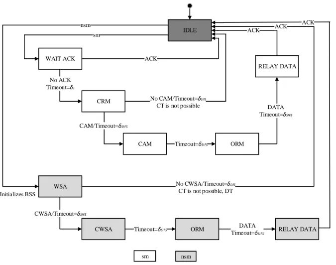
CWSA is introduced. ORM will be sent to the optimal relay. The internal finite state machine (FSM) of OEC-MAC protocol is shown in Figure 1, which is denoted by Unified Modeling Language (UML). There are 10 internal states and 15 external states defined in this FSM for standard packet processing. To process abnormal case timers will be set in accordance with duration values of packet header. If timeout happens, it resets as an “IDLE” state.
The total number of available subcarriers is assumed to be 64 but only 52 subcarriers are used for mapping. Before applying inverse fast Fourier transform (IFFT), 4 subcarriers from 52 subcarriers are selected to carry the pilot signal. Pilot symbols are used to predict the channel and to examine changes in the transmitted signal. Pilot subcarriers are used to make reliable sensing in the receiver against frequency shifts and phase noise. Table I shows OFDMA parameters in IEEE 802.11p standards [49].
In IEEE 802.11p, broadcast of sm are unacknowledged. Because of collision with other packets or wireless channel impairments, failed transmission of high priority sm cannot be identified. However, sm are very essential; thus, ACK is introduced in proposed protocol. ACK is only introduced for sm. Packets are not acknowledged will be considered as failed transmission. These packets will be sent via
IDLE WAIT ACK CRM CAM WSA ORM CWSA ORM RELAY DATA RELAY DATA sm nsm No ACK Timeout=δs Initializes BSS CAM/Timeout=δSIFS CWSA/Timeout=δSIFS
Timeout=δSIFS DATA
Timeout=δSIFS Timeout=δSIFS DATA Timeout=δSIFS ACK No CAM/Timeout=δSIFS CT is not possible ACK No CWSA/Timeout=δSIFS CT is not possible, DT ACK ACK sm nsm
2 VOLUME XX, 2020
cooperative communication to provide successful delivery. Therefore, reliability of transmission is improved. Even ACK is used, it does not affect the overall performance since different subcarriers are used.
Unicast mode of non-safety message transmission consumes too much bandwidth. If channel condition from source (S) to destination (D) is bad, but other neighboring nodes have a good channel condition to both S and D nodes, then neighboring nodes can relay a packet to D. Thus, transmission of nsm will be faster.
A. DELIVERY OF SAFETY MESSAGES
Source node S should understand whether the transmission is successful or not to ensure a reliable broadcast service. For this reason, ACK is implemented in the proposed OEC-MAC protocol. After transmission of sm, S will wait for ACK or timeout of s which is a successful transmission time. If S gets ACK, then the transmission is successful. Otherwise, it is a failed transmission. For unsuccessful packet delivery, S broadcasts CRM to all neighboring nodes. S broadcasts CRM to search relays. CRM includes CRM id, packet id, source address, destination address, SINR of source, etc. A node with good channel condition, better transmission rate, and SINR transmits CAM to S. CAM contains CRM ids, packet ids, address of relays, SINR of relays, etc. If S does not receive any CAM, it means there is no possible relay and cooperation is not possible.
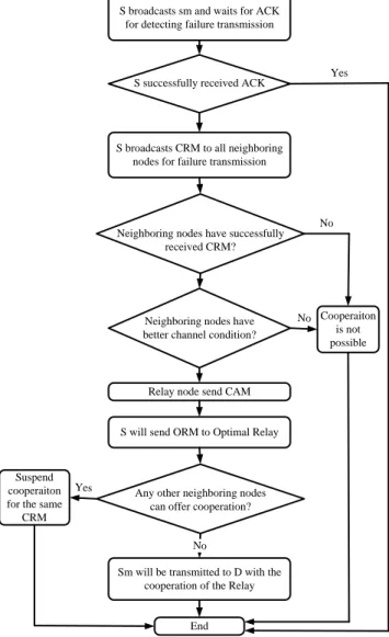
Then S will choose optimum relay between nodes who sent CAM. S will send ORM to optimum relay. Other nodes will suspend sending of CAM for the same CRM by listening to ORM. ORM is used to select the optimal relay. Then, sm will send to D through optimal relay R. This improves the reliability of packet delivery, and expands network coverage. The flowchart and algorithm of proposed OEC-MAC protocol for sm are presented in Figure 2 and Algorithm I, respectively.
B. DELIVERY OF NON-SAFETY MESSAGES
Nodes aiming to exchange nsm are called providers. A Wireless Access in Vehicular Environments (WAVE) provider (S) can be a road-side unit or a vehicle. Basic Service Set (BSS) is initialized by the S. The presence and offer services of S are advertised through periodic broadcast of WAVE Service Advertisement (WSA). WSA provides information on the services offered and the
S broadcasts sm and waits for ACK for detecting failure transmission
S broadcasts CRM to all neighboring nodes for failure transmission
Relay node send CAM
S will send ORM to Optimal Relay
Sm will be transmitted to D with the cooperation of the Relay
End Suspend
cooperaiton for the same
CRM Cooperaiton is not possible No Yes Yes No No
Any other neighboring nodes can offer cooperation? Neighboring nodes have better channel condition? Neighboring nodes have successfully
received CRM? S successfully received ACK
FIGURE 2. Flowchart of proposed OEC-MAC protocol for sm.
ALGORITHM I
ALGORITHM OF PROPOSED OEC-MAC PROTOCOL FOR SM 1. broadcast sm
2. wait=ACK 3. if ACK received 4. End
5. else if ACK is not received 6. broadcast CRM
7. send CAM which has better channel condition 8. send ORM to optimal Relay
9. if any nodes offer cooperation
10. suspend cooperation for the same CRM 11. else
12. successful transmission with the cooperation of Relay 13. end if
14. else no node has better channel condition 15. Discard cooperation 16. else 17. Discard cooperation 18. end if 19. else 20. Discard 21. end if TABLE I
OFDMA PARAMETERS IN IEEE 802.11P STANDARDS
Parameter Value
Total number of subcarrier 64 Total used subcarrier 52
Pilot subcarrier 4
Data subcarrier 48
Null subcarriers 12
Bandwidth
Frequency spacing of subcarriers
10 MHz 156.25 kHz
VOLUME XX, 2020
network parameters needed to access BSS, such as Provider Service Identifier (PSID), unique identifier of BSS (BSSID), WSA ID, its SCH, its EDCA parameter sets, IP configuration parameters, and provider SINR, etc. If overheard neighboring nodes (relay) have better SINR and better channel conditions, it will broadcast CWSA. CWSA includes all information of WSA, the identification of relay and channel information. S will choose the optimal relay after receiving CWSA, by sending ORM. Other nodes which can deliver cooperative transmission by hearing ORM can freeze cooperative communication for the same
WSA. Optimum relay will join BSS, and S will send nsm to D via optimum relay.
Destination (D) named as WAVE user which wants to have the offered service. To know present available BSS and their operational parameters D will monitor CCH. When a D node receives an ORM frame from S, it will simply switch to SCH advertised in ORM and start transferring data with optimal relay. Otherwise, if no ORM is identified, i.e., relay is not available, then D exchanges from S into SCH advertised in WSA and starts directly switching the data form S. The flowchart and algorithm of proposed OEC-MAC protocol for nsm are presented in Figure 3 and Algorithm II, respectively.
C. CHANNEL ACCESS
The vehicular node does not transmit immediately while the sub-channel is idle. It waits for the duration of DIFS,
which is DCF inter-frame space (DIFS). When channel is noticed to be idle, vehicle at the same distance may have started broadcasting earlier, and the packet of this remote vehicle may not have reached other vehicles yet. Hence, the DIFS time purpose is to allow this transmitted signal to reach other stations. If the channel is still idle for DIFS
S initializes a BSS and broadcast WSA
Relay broadcast CWSA
S will send ORM to Optimal Relay
D switches into SCH advertise in CWSA and start to exchange data
End Suspend
cooperaiton for the same
WSA Cooperaiton is not possible No Yes No No D switches into SCH advertise in WSA and start to exchange data Any other Neighboring nodes
can offer cooperation? Neighboring nodes have have
better channel condition? Neighboring nodes have successfully received WSA?
FIGURE 3. Flowchart of proposed OEC-MAC protocol for nsm.
ALGORITHM II
ALGORITHM OF PROPOSED OEC-MAC PROTOCOL FOR NSM 1. unicast nsm
2. initializes BSS and send WSA 3. if all nodes receive WSA
4. send CWSA which has better channel condition 5. send ORM to optimal Relay
6. if any nodes do not offer cooperation 7. send exchange data
8. else
9. suspend cooperation for the same WSA 10. end if
11. else if
12. Discard cooperation 13. send exchange data 14. end if
15. else if no node has better channel condition 16. Discard cooperation 17. end if 18. Discard 19. end if B1 B2 Bn Bn-1 Bn-2 B3 10 MHz DIFS ACK X failure Relay DATA OR Channel Contention ACK DATA
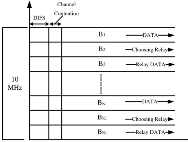
FIGURE 4. Channel access mechanism for sm.
B1 B2 BK3 BK2 BK1 B3 DIFS DATA Choosing Relay Relay DATA Relay DATA DATA Choosing Relay Channel Contention 10 MHz
VOLUME XX, 2020
time, S will send packet, otherwise will take a backoff based on contention window (CW) size. Despite all the precautions, collisions may occur, and data may be lost. Therefore, S will wait for ACK to verify successful transmission. While S node and D node are in communication, the used sub-channel is blocked and closed to other nodes.
Data transmission, acknowledgment, failed information, relay offering, relay data, and acknowledgment constitute a cooperative data transmission group with a total of six subcarriers for sm. The system with 48 subcarriers can have 08 simultaneous sm transmissions. Figure 4 shows channel access mechanism for sm.
A nsm transmission group consists of 3 subcarriers: data transmission, relay selection, and relay information transmission. The system with 48 subcarriers can have 16 simultaneous nsm transmission. Figure 5 shows channel access mechanism for nsm.
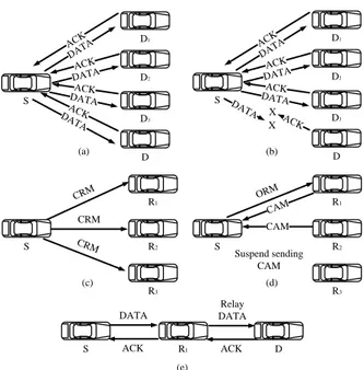
D. THREE PARTY HANDSHAKE
Three party handshakes among S, D, and R for sm and for nsm are shown in Figures 6 and 7, respectively. For sm, S
will initiate cooperative transmission if S doesn't get ACK from D. S will broadcast CRM and initializes cooperative communication for failed packet. Neighboring nodes that receive CRM will check their channel state. If neighboring nodes have better channel conditions for sm transmission, then they will suggest relaying by transmitting CAM. In Figure 6, R1 and R2 send CAM to S, as they have good
channel conditions for relaying sm. After SIFS time, S will select optimal R among nodes which send CAM. Then S will send ORM to optimal relay R1. Other nodes will suspend by
hearing to ORM to transmit CAM for the same CRM. CRM contains an own id no, and ORM contains the CRM id no to determine sm. Here R3 suspends transmitting CAM for the
same CRM. Then, S will send the sm to D through the optimal relay R1, and D will also send ACK through the
optimal relay R1. Cooperation will be initialized by S for sm,
and optimal R will be chosen by S too.
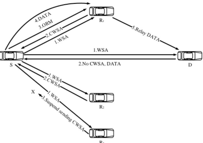
For nsm, S will broadcast WSA and offer services. Destination (D) named as WAVE user which wants to have the offered service. If neighboring nodes have better channel conditions and better SINR, then CWSA will be transmitted. R1 and R2 relay nodes send CWSA to S. After
SIFS time, S will select optimal relay between R1 and R2 by
observing their channel condition and SINR. S will send ORM to optimal relay R1, which is described in Figure 7.
Then R3 suspends transmitting CWSA for the same WSA
by hearing ORM. S will send nsm to D through optimal relay R1. For nsm, cooperation will be initiated by relay,
and optimal relay will be selected by S.
E. DATA TRANSMISSION
Data transmission is illustrated for sm and nsm in Figures 8 and 9, respectively. Successful direct transmission between source and destination is shown in Fig. 8a. S will wait for ACK information after sending the data. If S receives ACK, then this is a successful transmission. On the other hand, if S does not receive ACK, then S will detect failure transmission. Fig. 8b shows the failure transmission. Then, S initializes cooperation, and S will send CRM information. After getting CRM, neighboring nodes will understand failure transmission. Fig. 8c demonstrates neighboring nodes detect the failure of transmission by getting CRM. Then, neighboring nodes that has good channel condition will send CAM to make cooperation for failed transmission. S will select optimal relay among them and will send ORM to optimal relay. Other nodes will append to send CAM for the same CRM, which is exposed in Fig. 8d. Then, S will send data to optimal relay, and the optimal relay will send data to D. Again, D will send ACK to optimal relay, and the optimal relay will relay ACK to S. Data transmission through the optimal relay is shown in Fig. 8e.
For nsm, S will send data directly to D if S does not get any relay. Successful transmission of data between S and D is shown in Fig. 9a. If neighboring nodes have better channel conditions, and then they will broadcast CWSA. By getting CWSA, S will detect relay, which is demonstrated in Fig. 9b.
1.DATA X X S D R2 R3 R1
FIGURE 6. Three party handshakes among S, D, and R node or nodes for sm.
1.WSA 2.No CWSA, DATA
X
S D
R1
R2
R3
FIGURE 7. Three party handshakes among S, D, and R node or nodes for nsm.
VOLUME XX, 2020
Then, S will choose optimal relay, which has optimal channel condition among relays. S will send ORM to optimal relay, and other nodes will suspend sending CWSA after hearing ORM for the same WSA. Fig. 9c describes the selection of optimal relay and postponement of sending CWSA. Fig. 9d presents that the S will send data to D via optimal relay after selecting the optimal relay.
F. OPTIMAL RELAY SELECTION
Optimal relay R node is chosen by S for sm and nsm. However, S initializes cooperation for sm, and D initializes cooperation for nsm. Cooperation gain depends on relay R. By cooperative transmission, a low data rate node can broadcast data with a high data rate with the help of R.
For sm, the S sends CRM to initiate cooperation. Then neighboring nodes who have a higher SINR will send CAM to S. The SINR filed is included in CAM. Nodes that send CAM are considered as R. Then, S will realize the SINR of the relay from CAM. Then S will select the optimal relay which has optimal SINR, and S node will send ORM to the optimal relay. For nsm, neighboring nodes that have a higher SINR will transmit CWSA to S and initiates the cooperation. Nodes that broadcast CWSA to S are relay. SINR filed is included in CWSA. A node that has optimal SINR is the optimal relay. Then S will broadcast ORM to optimal relay. Here, relays are categorized as relay and optimal relay. The neighboring nodes that offer to relay in transferring data by broadcasting CAM or CWSA are relay. Relays have a higher SINR. An optimal relay is a relay that has optimal SINR among relays [50-52].
IV. PERFORMANCE ANALYSIS
A. THROUGHPUT ANALYSIS
A VANET is taken into account with N vehicles in the transmission range ( ). It is assumed that vehicles are randomly distributed and run on the multi-lane road.
Let
be mean arrival rate of vehicles, which can be given as [51].
L T
N d v
(1) where NL represents number of lanes on multi-lane road, v is velocity of the vehicle. dT denotes the traffic density.
Let t be transmission probability that a vehicle broadcasts a packet in a slot time. t for each subcarrier can be written as [48] 2 . ( 1) t sc CW (2) Since there are N a number of the subcarrier, sc t can be written as 2 . ( 1) t sc CW N (3) If at least one vehicle is broadcasting the packet within , channel will be busy, b can be shown as
1 1 t N.
b
(4) The collision occurs if at least one of remaining N-1 vehicles transmits a packet at the time slot, c can be expressed as 1 1 (1 t)N . c (5) s
is successful transmission probability that a packet transmission in the channel is successful which will be occurred if one station transmits on the channel in the slot time. s can be given as
CRM DATA ACK CRM CRM ORM CAM Suspend sending CAM CAM DATA ACK Relay DATA ACK (a) (b) (c) (d) (e) R1 R2 R3 R1 R2 R3 S S S D S R1 D2 D3 D D1 DATA ACK DATAACK DATAACK X X DATA ACK S D2 D3 D D1 DATA ACK DATA ACK DATA ACK
FIGURE 8. Data transmission for sm: (a) Successful broadcast of sm; (b) Failure transmission between S and D; (c) By getting CRM neighboring nodes detect the failure of transmission; (d) Neighboring nodes offer to relay, and S will the choose optimal R1; (e) Data
transmission through the optimal R1.
ORM DATA Suspend sending CWSA CWSA CWSA DATA Relay DATA (a) (b) (c) (d) S S S S D D R1 R2 R3 R1 R2 R3 R1
FIGURE 9. Data transmission for nsm, (a) Successful transmission between S (WAVE provider) and D (WAVE user); (b) By getting CWSA from neighboring nodes, S detect relays; (c) From relays, S chooses the optimal relay R1; (d) Data transmission through the optimal relay R1.
VOLUME XX, 2020
1 1 , N t t C b s H N c (6) where cCH shows the channel condition. Channel is modeled by a two-state Markov chain model (see appendix).d coop
is the probability of the decision of cooperative transmission. Cooperative transmission decisions will be performed after direct transmission fails, and there is at least one available relay for cooperative transmission. d coop can be given as
,
d coop b rNsc (7) where r, is getting helper probability, and it can be expressed as , r r N N (8) where Nr is the number of relays.
s coop
is successful transmission probability with cooperative transmission that packet transmission becomes successful with cooperative transmission. The transmission can be successful either by direct transmission or by cooperative transmission. s coop can be given as
1 (1 ) 1 1 . s coop s s s d coop N r sc t t CH b N N c (9)Let T be system throughput. T is data transmitted over a mean duration of slot time which can be expressed as
[ ]
,
e
E data transmitted in a slot time
T (10)
where E
. denotes expected value operator and e is expected time in Markov state. For sm and nsm, T can be shown in direct transmission as,
s dir b sm sm dir e dir sm L T (11) .
s dir b nsm dir r nsm e di nsm L T (12) Here, Lsm,Lnsm denote packet size for sm and nsm, respectively. For sm and nsm, in cooperative transmission, T can be given as ,
s coop b sm coop r e coo sm p sm L T (13) .
s coop b nsm coop r e p nsm coo nsm L T (14)For sm and nsm, e can be expressed for both direct transmission and cooperative transmission
(1 )
(1 ) ,
e dir sm b slot b s dir s dir sm
b s dir c
(15)(1
)
(1
) ,
e coop sm b slot b s coop s coop sm
b s coop c
(16) (1 ) (1 ) ,
e dir nsm b slot b s dir s dir nsm
b s dir c (17) (1 ) (1 ) ,
e coop nsm b slot b s coop s coop nsm b s coop c
(18) where, c and s are duration of collided and successful transmission, respectively. Broadcast mode of sm and unicast mode of nsm are take into account. For sm and nsm, s and
c
can be expressed for both direct transmission and cooperative transmission as follows:
,
h sm
dir sm M y s I dela d D FS CR L L R (19)
h nsm
,s dir nsm DIFS SIFS WSA del ya d L L R (20) , 3
h sm s c a oop sm DIFS SIFSCRM CAM d del y OHM L L R (21) , 3
h nsm s coop nsm DIFS SIFSWSA CWSA H d de O M lay L L R (22) , h c DIFS d delay L L R
(23) where SIFS,DIFS are the time duration for SIFS, DIFS,respectively. CRM,CAM,WSA,CWSA,ORM are the time required for CRM, CAM, WSA, CWSA, ORM, respectively.
delay
and Rd denote propagation delay and transmission rate, respectively.
For all transmission modes, the throughput variation equation based on the offered traffic load can be given as
(1 ) L L t L t t e T e
(24) where tL is offered traffic load. The traffic load is typically characterized by the average number of stations that request the service and the average duration of the stations that require the service.
is the normalized time unit( delay/e).
In addition, due to cooperative communication, the system throughput gain
can be calculated for both sm and nsm asVOLUME XX, 2020
,
sm coop sm dir sm sm coopT
T
T
(25) .
nsm coop nsm dir nsm nsm coop T T T (26)B. PACKET DROPPING RATE ANALYSIS
If the total probability is 1 (probability of successful transmission + probability of packet dropping), the packet dropping rate is 1 - the probability of successful transmission. For direct transmission, packet dropping rate ( ) can be calculated as [48]
(1 ).
s DT (27)
After the failure of direct transmission, a packet will be transmitted with cooperative transmission. For cooperative transmission, if m denotes the number of cooperation attempts, can be written as [48]
(1 ) .
s CT m (28) C. DELAY ANALYSIS
Time duration from the creation of a frame to its successful transmission is frame delay. Let E [ ] be a delay which can be written as:
[ ] [ ]( [ ] c w) ( [ ] s),
E E
E
E
(29) where E[ ]
is the average number of collisions of a frame until successful transmission, E[ ]
is backoff delay that is the backoff of a vehicle before accessing the channel, and w is the waiting time of a vehicle to sense the channel again after a collision. w can be given as.
w SIFS
(30) [ ]
E
can be obtained from the successful transmission probability s, which can be given as1 [ ] 1. s E (31) [ b]
E depends on backoff counter value and paused time of counter when the channel is busy. If backoff counter at c and
to reach 0, bc slot times is needed without considering pause of the counter. The mean of this time interval can be written as 1 1 0 0 0 [ ] ( 1)( 2) . ( 1) CW CW c sc c c CW c E cb c b CW C N W CW CW
(32)Let E [ ] is the mean time a vehicle counter freeze, E N[ ] is mean number of times that a vehicle senses transmission from other vehicles before the backoff counter becomes 0, and E [ ] is average number of consecutive idle times before transmission occurs. The relationship between these parameters can be shown as
[ ] [ ] 1, max( [ ],1) E E N E (33) [ ] [ ]( s s (1 s) c), E E N (34) 1 [ ] 1. b E (35) By using (32) to (35), E [ b] can be written as
[ ] [ ] [ ]( s s (1 s) c).
E E E N (36) Here, s and c can be calculated by using (19) to (23). Therefore, E [ ] can be obtained by substituting (30), (31), and (36) into (29).
V. NUMERICAL RESULTS
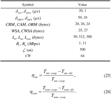
The performance of proposed OEC-MAC protocol is investigated in this section. sm and nsm are taken into account. Numerical analysis is conducted in MATLAB. We assume saturated condition and an ideal channel condition. We also assume that vehicles are running on two-lane road. In numerical results, proposed OEC-MAC protocol is compared with RECV-MAC [48] and traditional MAC, which based on IEEE 802.11p [25]. A quantitative comparison is provided with existing MAC mechanisms too. Values of parameters used for numerical analysis are presented in TABLE II.
Figure 10 shows throughput against number of vehicles. There is a significant improvement in OEC-MAC protocol for sm and nsm transmission for VANETs. The throughput increases to a certain point, and then the throughput decreases. Since fewer vehicles cannot cause collisions, throughput begins to increase with growing vehicle nodes, but as vehicles increase, vehicles cause more collisions and reduces throughput. However, in the proposed OEC-MAC, the throughput is particularly good in high traffic scenarios. Due to cooperation, S-R link will be more reliable for transmitting packet, and transmission will be faster with good channel conditions. Because of CSMA/CA, RECV-MAC protocol has higher throughput when there is low traffic compare to OEC-MAC. However, when the traffic is
TABLE II
PARAMETER VALUES USED IN NUMERICAL ANALYSIS
Symbol Value , ( ) slot delay s 20, 1 , ( ) DIFS SIFS s 50, 10 , , ( )
CRM CAM ORM bytes 20, 26, 24
, ( )
WSA CWSA bytes 25, 27
, ( ) h sm nsm L L L bytes 50, 512, 300 , ( ) c d R R Mbps 1, 11 ( ) m 500 CW 64
VOLUME XX, 2020
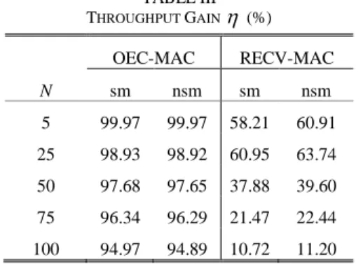
increasing, OEC-MAC is better than the RECV-MAC protocol. Throughput for OEC-MAC protocol is higher because of OFDMA. Since OFDMA enables current data transmission through different subcarrier channels, the probability of collision is lower. Throughput gain comparison between OEC-MAC and existing RECV-MAC protocols is given in Table III.
Figure 11 shows throughput against velocity of vehicles. Throughput decreases dramatically with increasing velocity as high mobility between vehicular nodes can cause rapid topology changes. However, the proposed OEC-MAC protocol increases throughput under different velocity in VANETs due to cooperative communication and OFDMA.
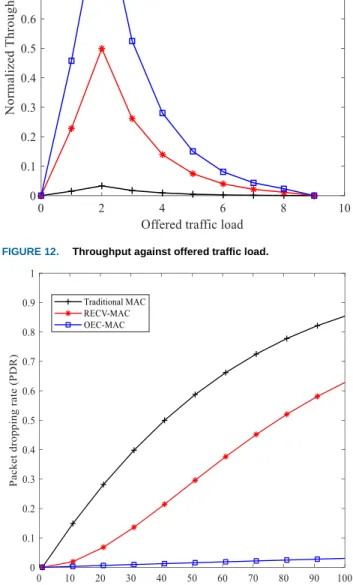
Figure 12 demonstrates normalized throughput versus offered traffic load. Throughput increases with the increase of offered load and then starts to fall which follows a normal distribution. Offered traffic load starts with 20 vehicles, represents as 1 and increases by 20 vehicles in each increase of offered load. OEC-MAC has the highest throughput.
Figure 13 presents packet dropping rate (PDR) against number of vehicles. Packet dropping rate increases with increase of the number of vehicles because collision probability increases. When there are more nodes, probability of packet arrival increases, which results in more contention and more collisions. OEC-MAC protocol provides reliable transmission by reducing packet dropping rate. Because of
FIGURE 12. Throughput against offered traffic load.
FIGURE 13. Packet dropping rate against number of vehicles. FIGURE 10. Throughput against number of vehicles.
VOLUME XX, 2020
subcarrier, simultaneous packets access and transmission through different subcarrier channels can decrease collision probability. Therefore, OEC-MAC has lowest PDR.
Figure 14 demonstrates average packet delay versus number of vehicles. Since there will be more packet to send, the average packet delay increases with number of vehicles. For transmission, these additional packets will result in extended probability of channel busy and collision for the channel in the same time period. Therefore, the average packet delay increases. Cooperative communication increases successful transmission probability. Thus, RECV-MAC and OEC-RECV-MAC have lower delay than traditional MAC. It is noticeable that both RECV-MAC and traditional
MAC has lower delay than OEC-MAC protocol because both of them use CSMA/CA and when there is low traffic CSMA/CA performs better. Since CSMA/CA uses full channel, the packet is transmitted with higher bandwidth than OEC-MAC. On the other hand, CSMA/CA does not perform well in the case of high traffic scenario because of high collision probability. High collision probability increases backoff and keeps channel busy longer. Therefore, both RECV-MAC and traditional MAC protocols have higher delay in high traffic. On the other hand, OEC-MAC reduces channel busy and collision probability by subcarrier channel of OFDMA mechanism. Instead of contending in one channel, packets will contend for different subcarrier channels which will reduce probability of channel busy and collision. Therefore, OEC-MAC has lower delay than RECV-MAC in high traffic.
Figure 15 shows average packet delay versus velocity. Delay increases with the increase of vehicle velocity. Since network topology changes rapidly with velocity which makes communication unstable and causes packet loss and collision, delay increases. However, OEC-MAC protocol reduces latency in VANETs due to OFDMA and cooperative communication. The same issue is also noticeable in this figure. When traffic is low, traditional MAC and RECV-MAC protocols have lower delay than OEC-RECV-MAC. On the other hand, OEC-MAC has lower delay than traditional MAC and RECV-MAC protocols when traffic is high.
In the existing cooperative MAC mechanisms, under the same network scenario, maximum throughput is about 3.5, 3.5, 7, 16 Mbps, in [36, 41, 43, 48], respectively. However, the OEC-MAC protocol achieves a maximum throughput of about 16.3 Mbps. Delay analysis is not studied in [37, 41, 42]. Delay constraint of sm cannot be satisfied in [40, 41, 43]. Though [48] satisfies 100 ms delay requirement for sm in VANETs, OEC-MAC has lower delay than [48] in high traffic scenario.
VI. CONCLUSION AND FUTURE WORKS
In this paper, a novel OFDMA based efficient cooperative MAC protocol is proposed for VANETs, which is named as OEC-MAC. New control messages have been presented to provide effective cooperative communication. Data transmission mode is divided into two categories- direct
TABLE III THROUGHPUT GAIN
(%) OEC-MAC RECV-MAC N sm nsm sm nsm 5 99.97 99.97 58.21 60.91 25 98.93 98.92 60.95 63.74 50 97.68 97.65 37.88 39.60 75 96.34 96.29 21.47 22.44 100 94.97 94.89 10.72 11.20FIGURE 14. Delay versus the number of vehicles.
VOLUME XX, 2020
transmission and cooperative transmission. The mechanism of optimal relay selection is also described. An analytical analysis based on the Markov chain model of OEC-MAC protocol is demonstrated. Network performance metrics, such as successful transmission probability, channel busy probability, collision probability, throughput, packet dropping rate, and delay are derived. OEC-MAC protocol performance is examined by numerical analysis, and a quantitative comparison is provided. Numerical results show that OEC-MAC protocol increases data rate, decreases packet dropping rate and delay, and fulfills 100 ms latency requirement for sm. Moreover, OEC-MAC performs better than any other existing protocols in heavy traffic scenarios. In future research, we will consider the unsaturated condition. Performance analysis under capture effect and channel fading also includes future research work.
APPENDIX
G
B
Δ
GBΔ
BGΔ
GGΔ
BBΔ
GGΔ
BBG
G
B
B
FIGURE 16. Two state discrete Markov chain model for channel condition.
Two-state discrete-time Markov chain model is presented in Figure 16. Wireless channels may be in good (G) or bad (B) conditions. SINR at any moment is taken from a uniform distribution in the range of 15 to 30 dB when wireless channel is in G condition. SINR value is taken in a range of 0 to 15 dB when wireless channel is in B condition. A packet is successfully transmitted when state is in G condition. If channel is in B condition, it will be a failed transmission. The success or failure of transfer depends only on the current channel situation.
GB
and BG are state transition probabilities. The transition between the two states takes place instantly on each packet. State transition matrix can be presented as
. GG GB BB BG REFERENCES
[1] IEEE 802.11p-2010: ‘IEEE standard for information technology – local and metropolitan area networks – specific requirements – part 11: wireless LAN medium access control (MAC) and physical layer
(PHY) specifications amendment 6: wireless access in vehicular environments’, 2010.
[2] ITS G5–2009: ‘European telecommunications standards institute, ‘intelligent transport systems (ITS); European profile standard for the physical and medium access control layer of intelligent transport systems operating in the 5 GHz frequency band,’ ETSI, ES, 202 663 V1.1.0’, 2009.
[3] IEEE 1609.4-2016: ‘IEEE standard for wireless access in vehicular environments (WAVE) — multi-channel operation’, 2016.
[4] A. Sendonaris, E. Erkip and B. Aazhang, “User cooperation diversity - Part I and Part II: System description,” IEEE Transactions on
Communication, pp. 1927–1938, 2003.
[5] S. Srikanth, P. Murugesa Pandian, and X. Fernando, “Orthogonal
frequency division multiple access in WiMAX and LTE: A comparison,” IEEE Commun. Mag., vol. 50, no. 9, pp. 153–161, Sep. 2012.
[6] D. Matolak, Q. Wu, J. Sanchez-Sanchez, D. Morales-Jimenez, and
M. Aguayo-Torres, “Performance of LTE in vehicle-to-vehicle channels,” in Proc. IEEE VTC Fall, Sep. 2011, pp. 1–4.
[7] B. Wang, I. Sen, and D. Matolak, “Performance evaluation of 802.16e
in vehicle to vehicle channels,” in Proc. IEEE 66th VTC Fall, Oct. 2007, pp. 1406–1410.
[8] H. Ferdous and M. Murshed, “Ad hoc operations of enhanced IEEE
802.11 with multiuser dynamic OFDMA under saturation load,” in
Proc. IEEE WCNC, Mar. 2011, pp. 309–314.
[9] H. Kwon, H. Seo, S. Kim, and B. G. Lee, “Generalized CSMA/CA for
OFDMA systems: Protocol design, throughput analysis,
implementation issues,” IEEE Trans. Wireless Commun., vol. 8, no. 8, pp. 4176–4187, Aug. 2009.
[10] H. Xiong and E. Bodanese, “A scheme to support concurrent transmissions in OFDMA based ad hoc networks,” in Proc. IEEE VTC
Fall, Sep. 2009, pp. 1–5.
[11] S. Patil, M. Anand, X. Wu, and J. Li, “Effective OFDMA based
signaling in ad-hoc wireless networks,” in Proc. IEEE GLOBECOM, Dec. 2011, pp. 1–6.
[12] K. Hamdi, “Precise interference analysis of OFDMA
time-asynchronous wireless ad-hoc networks,” IEEE Trans. Wireless
Commun., vol. 9, no. 1, pp. 134–144, Jan. 2010.
[13] R. Rashtchi, R. Gohary, and H. Yanikomeroglu, “Joint routing,
scheduling and power allocation in OFDMA wireless ad hoc networks,” in Proc. IEEE ICC, Jun. 2012, pp. 5483–5487.
[14] M. Veyseh, J. Garcia-Luna-Aceves, and H. Sadjadpour, “Cross-layer channel allocation protocol for OFDMA ad hoc networks,” in Proc.
IEEE GLOBECOM, Dec. 2011, pp. 1–6.
[15] M. Veyseh, J. Garcia-Luna-Aceves, and H. Sadjadpour, “OFDMA based multiparty medium access control in wireless ad hoc networks,” in Proc. IEEE ICC, June pp. 1–6.
[16] K. Abdel Hafeez, L. Zhao, Z. Liao, and B. Ma, “Clustering and
OFDMA based MAC protocol (COMAC) for vehicular ad hoc networks,” EURASIP J. Wireless Commun. Netw., vol. 2011, no. 1, pp. 1–16, 2011.
[17] A. Bazzi, B. Masini, and F. Zabini, “On the exploitation of OFDMA properties for an efficient alert message flooding in VANETs,” in
Proc. IEEE ICC, Jun. 2013, pp. 5094–5098.
[18] A. Bazzi, B. Masini, A. Zanella, and G. Pasolini, “On the use of OFDMA for next generation vehicular ad hoc networks,” in Proc.
IEEE Int. Symp. PIMRC, Sep. 2013, pp. 2223–2228.
[19] M. F. Feteiha and H. S. Hassanein, "Enabling cooperative relaying VANET clouds over LTE-A networks," in IEEE Transactions on
Vehicular Technology, vol. 64, no. 4, pp. 1468-1479, April 2015.
[20] M. Noor-A-Rahim, G. G. M. N. Ali, Y. L. Guan, B. Ayalew, P. H. J. Chong and D. Pesch, "Broadcast performance analysis and improvements of the LTE-V2V autonomous mode at road intersection," in IEEE Transactions on Vehicular Technology, vol. 68, no. 10, pp. 9359-9369, Oct. 2019.
[21] J. Hu et al., "Link level performance comparison between LTE V2X and DSRC," in Journal of Communications and Information
Networks, vol. 2, no. 2, pp. 101-112, June 2017.
[22] IEEE Std 802.11-2016: ‘IEEE standard for information technology – telecommunictions and information exchange between systems local and metropolitan area networks-specific requirements – part 11:
VOLUME XX, 2020
wireless LAN medium access control (MAC) and physical layer (PHY) specifications’, 2016.
[23] C. Han, M. Dianati, R. Tafazolli, ‘Analytical study of the IEEE 802.11p MAC sublayer in vehicular networks’, IEEE Trans. Intell.
Transp. Syst., vol. 13, no. 2, pp. 873–886, 2012.
[24] K. Xu, D. Tipper, Y. Qian, ‘Time-dependent performance analysis of IEEE 802.11p vehicular networks’, IEEE Trans. Veh. Technol., vol. 65, no. 7, pp. 5637–5651, 2016.
[25] A. F. M. S. Shah, H. Ilhan and U. Tureli, "Modeling and performance analysis of the IEEE 802.11p MAC for VANETs," in Proc. of IEEE
42nd International Conference on Telecommunications and Signal Processing (TSP), Budapest, Hungary, 2019, pp. 393-396.
[26] Y. Yao, L. Rao, X. Liu, ‘Performance and reliability analysis of IEEE 802.11p safety communication in a highway environment’, IEEE
Trans. Veh. Technol., vol. 62, no. 9, pp. 4198–4212, 2013.
[27] X. Cheng, R. Zhang, L. Yang, ‘Wireless toward the era of intelligent vehicles’, IEEE Internet Things J., vol. 6, no. 1, pp. 188–202, 2019. [28] H. Kwon, H. Seo, S. Kim, and B. G. Lee, “Generalized CSMA/CA for
OFDMA systems: Protocol design, throughput analysis, implementation issues,” IEEE Trans. Wireless Commun., vol. 8, no. 8, pp. 4176–4187, Aug. 2009.
[29] H. Xiong and E. Bodanese, “A scheme to support concurrent transmis- sions in OFDMA based ad hoc networks,” in Proc. IEEE VTC Fall, Sep. 2009, pp. 1–5.
[30] S. Patil, M. Anand, X. Wu, and J. Li, “Effective OFDMA based signaling in ad-hoc wireless networks,” in Proc. IEEE GLOBECOM, Dec. 2011, pp. 1–6.
[31] K. Hamdi, “Precise interference analysis of OFDMA time-asynchronous wireless ad-hoc networks,” IEEE Trans. Wireless
Commun., vol. 9, no. 1, pp. 134–144, Jan. 2010.
[32] R. Rashtchi, R. Gohary, and H. Yanikomeroglu, “Joint routing, scheduling and power allocation in OFDMA wireless ad hoc networks,” in Proc. IEEE ICC, Jun. 2012, pp. 5483–5487.
[33] M. Veyseh, J. Garcia-Luna-Aceves, and H. Sadjadpour, “Cross-layer channel allocation protocol for OFDMA ad hoc networks,” in Proc.
IEEE GLOBECOM, Dec. 2011, pp. 1–6.
[34] M. Veyseh, J. Garcia-Luna-Aceves, and H. Sadjadpour, “OFDMA based multiparty medium access control in wireless ad hoc networks,” in Proc. IEEE International Conference on Communications, Dresden, 2009, pp. 1-6.
[35] F. Yang, Y. Tang, ‘Cooperative clustering-based medium access control for broadcasting in vehicular ad-hoc networks’, IET Commun., vol. 8, no. 17, pp. 3136–3144, 2014.
[36] T. Zhou, H. Sharif, M, Hempel, ‘A novel adaptive distributed cooperative relaying MAC protocol for vehicular networks’, IEEE J.
Sel. Areas Commun., vol. 29, no. 1, pp. 72–82, 2011.
[37] S. Bharati, W. Zhuang, ‘CAH-MAC: cooperative ADHOC MAC for vehicular networks’, IEEE J. Sel. Areas Commun., vol. 31, no. 9, pp. 470–479, 2013.
[38] S. Bharati, L. V. Thanayankizil, F. Bai, ‘Effects of time slot reservation in cooperative ADHOC MAC for vehicular networks’.
Proc. IEEE ICC, Budapest, Hungary, June 2013, pp. 6371–6375.
[39] R. Woo, D. S. Han, ‘A cooperative MAC for safety-related road information transmission in vehicular communication systems’. Proc.
IEEE 1st Global Conf. on Consumer Electronics, Tokyo, Japan,
October 2012, pp. 672–673.
[40] H. Omar, W. Zhuang, A. Abdrabou, ‘Performance evaluation of VeMAC supporting safety applications in vehicular networks’, IEEE
Trans. Emerg. Top. Comput., vol. 1, no. 1, pp. 69–83, 2013.
[41] J. Zhang, Q. Zhang, W. Jia, ‘VC-MAC: a cooperative MAC protocol in vehicular networks’, IEEE Trans. Veh. Technol., vol. 58, no. 3, pp. 1561–1571, 2009.
[42] S. Bharati, W. Zhuang, ‘CRB: cooperative relay broadcasting for safety applications in vehicular networks’, IEEE Trans. Veh. Technol., vol 65, no. 12, pp. 9542–9553, 2016.
[43] L. Zhang, B. Jin and Y. Cui, "A concurrent transmission enabled cooperative MAC protocol for Vehicular Ad Hoc Networks," IEEE
22nd International Symposium of Quality of Service (IWQoS), Hong
Kong, 2014, pp. 258-267.
[44] A. Zanella, A. Bazzi and B. M. Masini, "Relay selection analysis for an opportunistic two-hop multi-user system in a poisson field of
nodes," in IEEE Transactions on Wireless Communications, vol. 16, no. 2, pp. 1281-1293, Feb. 2017.
[45] C. La Palombara, V. Tralli, B. M. Masini and A. Conti, "Relay-assisted diversity communications," in IEEE Transactions on
Vehicular Technology, vol. 62, no. 1, pp. 415-421, Jan. 2013.
[46] A. Mchergui, T. Moulahi and S. Nasri, "Relay selection based on deep learning for broadcasting in VANET," 15th International Wireless
Communications & Mobile Computing Conference (IWCMC),
Tangier, Morocco, 2019, pp. 865-870.
[47] A. Mchergui, T. Moulahi and S. Nasri, "Measuring QoS for broadcasting task in vehicular ad hoc networks based on fuzzy logic projection," 30th International Conference on Microelectronics
(ICM), Sousse, Tunisia, 2018, pp. 192-195.
[48] A. F. M. S. Shah, H. Ilhan and U. Tureli, "RECV-MAC: A novel reliable and efficient cooperative MAC protocol for VANETs," in IET
Communications, vol. 13, no. 16, pp. 2541-2549, Oct. 2019.
[49] A. M. S. Abdelgader, W. Lenan, " The physical layer of the IEEE 802.11p WAVE communication standard: the specifications and challenges," World Congress on Engineering and Computer Science, San Francisco, USA, 2014, pp. 1-8.
[50] S. S. Ikki and M. H. Ahmed, "On the performance of cooperative-diversity networks with the nth best-relay selection scheme," in IEEE Transactions on Communications, vol. 58, no. 11, pp. 3062-3069, Nov. 2010.
[51] C. Qin and K. Xiao, "Performance analysis of a multi-user relay selection scheme with predicted SINR in the presence of co-channel interference," in Proc. of IEEE 8th International Conference on
Communication Software and Networks (ICCSN), Beijing, 2016, pp.
171-176.
[52] Q. Wang and Y. Jing, "Closed-form average SNR and ergodic capacity approximations for best relay selection," in IEEE Transactions on Vehicular Technology, vol. 65, no. 4, pp. 2827-2833, April 2016.
[53] T. H. Luan, X. Ling and X. Shen, "MAC in motion: impact of mobility on the MAC of drive-thru internet," in IEEE Transactions on
Mobile Computing, vol. 11, no. 2, pp. 305-319, Feb. 2012.
MUHAMMET ALI KARABULUT (S’14) received his B.Sc. degree in electrical and electronics engineering from the Mustafa Kemal University, Hatay, Turkey in 2010. He completed his M.Sc. degree in electronics and communication engineering from Yildiz Technical University, Istanbul, Turkey in 2015. Since 2013, he is a research and teaching assistant in department of electronics and communication engineering at Yildiz Technical University. He is currently pursuing the Ph.D. degree in electronics and communication engineering at Yildiz Technical University, Turkey. His research areas include digital communication, cooperative communication, MAC protocols for vehicular ad hoc networks.
VOLUME XX, 2020
A. F. M. SHAHEN SHAH (M’17 - SM’19) received his B.Sc. degree in Electronics and Telecommunication Engineering from the Daffodil International University, Bangladesh, in 2009. He completed his M.Sc. degree in Information Technology from the University of Dhaka, Bangladesh, in 2011. He studied M.Sc. degree in Information and Communication Technology from the Bangladesh University of Engineering and Technology, Bangladesh, in 2013. He received the Ph.D. degree in Electronics and Communication Engineering from the Yildiz Technical University, Turkey, in 2020. Since 2020, he has been working as an Assistant Professor in the Department of Electrical and Electronics Engineering, Istanbul Gelisim University, Turkey. He also worked in industry for last ten years where he served as a higher management position. His current research interest includes cross-layer design, modeling and performance analysis of wireless communications systems. Specific research areas include cluster-based communication, cooperative communication, MAC protocols for vehicular ad hoc networks and UAVs ad hoc networks. He is an author of a book. He has published a good number of research papers in international conferences and journals. He is a senior member of IEEE and a life member of the Institution of Engineers, Bangladesh (IEB).
HACI ILHAN (M’07 - SM’19) received the B.Sc. degree in electronics and communication engineering from Yildiz Technical University, Istanbul, Turkey. The M.Sc. and the Ph.D. degree all in electronics and communication engineering from Istanbul Technical University, Istanbul, Turkey. From 2001 to 2011 he was a research and teaching assistant in communication department at Istanbul Technical University. Since 2011, he has been with the Department of Electronics and Communication, Yildiz Technical University, Istanbul, Turkey, where he is an Associate Professor. His general research interests lie in communications theory and signal processing for communications with particular emphasis on wireless applications. Specific research areas include cooperative communication, MIMO communication techniques, space-time coding, multicarrier communication, MAC protocols for vehicular ad hoc networks. Dr. Ilhan is an IEEE senior member.