1Abstract—Traffic control systems for an urban traffic management play an important role in reducing congestion and the negative effects of social and economic aspects. In this paper, the coordinated control method for an arterial road network is proposed. The proposed method is based on fuzzy logic and Webster optimum cycle formula. It is a cyclic method, which means that all-feasible phases at the intersection are get at least a minimum green signal during each cycle. These minimum green times can be used for pedestrian crossing purposes. This method eliminates the starvation that occurs at minor roads due to the non-cyclic strategy. The proposed method is investigated in both coordinated and isolated circumstances. It is compared with non-optimized fixed time control and the cyclic backpressure strategy suggested in the literature. The cyclic backpressure strategy was selected due to its similarity with our proposed method. Based on the obtained results, the adaptive fuzzy logic and Webster based coordinated method outperforms the other methods in terms of the average of waiting time, travel time, travel speed, and queue lengths. In addition, the result achieved from a coordinated situation slightly superior that obtained from isolated situation, which means the proposed method provides good performance both in an isolated and coordinated situations.
Index Terms—Adaptive traffic control; Fixed time traffic control; Fuzzy logic; SUMO simulator; Webster’s optimal cycle formula.
I. INTRODUCTION
The momentous of traffic signal control comes from its impact on the social and economic aspects of humans’ living. It is a method for managing a conflicting mixed movement of vehicles, motorcycles, and pedestrians, which share a common resource. Traffic control in the urban area around the world is a continuous challenge, despite the attempts of many city planners to extend the road infrastructure. In fact, the extending of road infrastructure is limited compared to the increasing rate of number of vehicles. The congestion problem in urban areas is increasing daily as the number of vehicles rises. The congestion commonly occurs at intersections. The utilization of a proper control plan for traffic management can prevent
Manuscript received 23 March, 2020; accepted 9 June, 2020.
congestion unless the maximum capacity of the intersection situation takes place. The traffic signal control can be categorized based on its operational principle to four types: traditional or fixed time, semi-actuated, fully actuated, and adaptive control methods. The traffic control is considered as one of the typical examples of a complex system due to its nonlinearity dynamics, time-variant, and stochastic nature [1]. The parameters that can be optimized in traffic signal control include cycle length, green interval, offset, and phase sequence. These parameters are either constant as in the case of fixed time traffic control or changeable as in adaptive traffic signal control [2]. The traditional traffic control systems that built based on historical data have become impractical in many situations with variable traffic volumes. Conversely, adaptive traffic control systems are suitable and desirable to meet the requirements of today’s traffic demands.
Most of the achieved works in the literature are non-cyclic strategies, which means there is no green time allocated to every phase within each cycle. This may lead to unpredictable long delays at least at the minor roads. To overcome such a drawback, we proposed a cyclic method that assigns a green signal for all phases during each cycle. These green times varied within the minimum and maximum times.
In this paper, we aim to build a feedback control that adjusts the cycle time through the Webster’s formula and the phase green time through the fuzzy logic to adapt to varying traffic demands. The main advantages of this method are fully distributed, scalable, and easy to implement the strategy.
II. THE RELATED WORKS
Nowadays, the traffic signal control has become urgent in urban areas to reduce the congestion problem. Many works have been achieved in this field by employing several optimization algorithms to obtain performance enhancement.
Since Webster published his famous minimum delay optimal cycle formula in 1958, the formula became dominant in the field of fixed time traffic control for an
Fuzzy Logic and Webster’s Optimal Cycle
Based Decentralized Coordinated Adaptive
Traffic Control Method
Muzamil Eltejani Mohammed Ali
1, *, Akif Durdu
1, Seyit Alperen Celtek
2,
Seyfettin Sinan Gultekin
1 1Department of Electrical and Electronics Engineering, Konya Technical University,
Ardicli Mah. Rauf Orbay Cad. 42250, Selcuklu/Konya, Turkey
2
Department of Energy Engineering, Karamanoglu Mehmetbey University,
Yunus Emre Yerleskesi, 70200 Karaman, Turkey
isolated intersection [3]. However, until now, this formula has been limited to calculate the optimal cycle from historical data for a pre-timed traffic signal control. There are many modified versions of Webster minimum delay optimal cycle formula [4]. Although this method has been decades old, it is still applicable to modern systems. Presently, most of optimization and modern control algorithms are applied to optimize the traffic signal control system.
Fuzzy logic is one of the most common methods used in traffic signal control systems. Zadeh has introduced the fuzzy set theory in 1965 and became a new alternative of uncertainty treatment applied to various fields of a control system, including transportation systems. Fuzzy logic is the interpretation and transformation of expert knowledge into a practical reality [5], [6]. A lot of fuzzy logic based traffic control contributions are applied to an isolated intersection. Among these works, Soh et al. developed a traffic model and fuzzy traffic controller for multilane isolated intersection using MATLAB Simulink and SimEvent toolbox. The traffic model is designed based on the queue theory and the control decisions determined by the queue length and the waiting time of a vehicle in the edges. The traffic controller optimizes both phase timing and sequence of a traffic signal in order to obtain a good performance. To evaluate the performance, the controller was compared to traditional vehicle-actuated control and the controller demonstrate a good performance [7]. In another work, a dynamic control system based on fuzzy logic was proposed. The system combines the wireless sensor network with four fuzzy logic controllers. Zigbee based wireless sensor network was used to monitor real-time traffic data. The simulation was performed based on MATLAB/Simulation and the better result in terms of reducing vehicle waiting time, especially in heavy traffic situations, was achieved [8]. On the other hand, fuzzy logic based studies applied to arterial or urban networks have also existed. Kermanian et
al. introduced a comprehensive model of urban traffic
network based on the state space equation by utilizing fuzzy logic. The fuzzy model of urban traffic network was conducted for two intersections. Local and neighbouring traffic information was used in order to achieve coordination between intersections. The obtained result shows that the performance of fuzzy logic controller in congestion is better than in normal situation [9]. Balaji and Srinivasan presented a multi-agent system based on type-2 fuzzy logic. The complex urban road network traffic control is tested as a case study. The proposed system is based on the agent model. In order to analyse the improvement of the model, the average delay and current average speed of vehicles are used as performance metrics. To measure the performance of the system, the further two available systems were used as benchmarks because they had tested in the same traffic network under the same conditions. The obtained result offered better performance compared to the other two models [10]. Lee and Lee-Kwang presented a cooperative traffic signal control for a group of intersections by applying fuzzy logic theory. The proposed controller changes the time and the sequence of phases according to traffic situations in order to maximize the performance of the method. The controller was compared with the vehicle-actuated method
under the same conditions and the simulation was performed for eighteen different conditions. A good performance was obtained [11]. Shen and Kong introduced a cooperative traffic system that allows sharing the information between neighbouring intersections and takes into account the priority of busses to cross the intersection. The system is designed based on fuzzy logic and neural network. The suggested controller was compared to the isolated fixed time intersection control method to demonstrate the performance improvement of the system [12]. Shen and Kong also presented a method that separates the arterial road intersections into subarea dynamically to enhance the performance of the traffic signal. The proposed system operates under isolated or coordinated mode; depending on the correlation degree between adjacent intersections. The method was compared to an adaptive control method applied to an isolated intersection. Although the proposed method showed the superior in terms of performance, however, it has a drawback when the arterial road is near to saturation or the traffic volume of a lot of branches is huge and near to that of the arterial road [13]. Other interesting contributions include the work in [14]. It is based on a distributed cooperative backpressure-based traffic control algorithm. The algorithm was applied to urban traffic networked road. In this method, intersections act as a smart agent that communicate with each other to share the information, such as queue length and the active phase duration of the neighbouring intersection. Beside the local information, the active phase state of the downstream intersection is used to make a decision at a local intersection. As a simulation, the proposed method was compared to the original backpressure and fixed time control and the better performance result was obtained. Further, backpressure-based algorithm was proposed in [15]. Is a capacity-aware backpressure method applied to a traffic road network. The suggested algorithm was intended to overcome the weakness of the origin backpressure algorithm by using normalized pressure as queue boundedness constrain. The algorithm was compared to the original backpressure and fixed time control. The better performance result was obtained, especially in heavy traffic conditions.
There are further researches performed in the field of traffic signal control using different methods and different optimization algorithms, such as Petri net [16], Bee colony optimization algorithm [17], deep learning algorithm [18], and Dynamic Programming [19]. The most of above-mentioned methods either are non-cyclic strategies or applied to isolated intersections.
III. THE PROPOSED METHODS
In this section, we discuss the proposed decentralized coordinated adaptive fuzzy logic and Webster’s optimal cycle formula. In this method, the cycle time is estimated using modified Webster’s formula and the fuzzy logic is used to make a decision on adjusting green time in an online manner. The coordination between distributed intersections is provided through the phase sequence reordering at the beginning of each cycle.
A.
The Calculation of Cycle Lengtheach cycle the optimal cycle length for the next cycle is calculated as in (1). This formula is suggested in [4] and referred to as a modified version of Webster’s optimal cycle formula 1 1.978 5.109 ( ) . 1 0.9013 ( ) o m j j L C n Y n
(1)L is the total intersection losses and Yj(n) represents the
critical flow of the phase j (j = 1, 2, …, 4) at the cycle n. The upper and lower cycle time limits were used to prevent underestimation and overestimation of the cycle time. The predefined minimum of 32 s and maximum of 100 s cycle time have been used for all intersections. The total loss time is set to 12 s for each intersection. 3 seconds are given for each phase, which is represented by yellow signal.
B. The Calculation of Split Time
The calculation of green split is performed depending on the ratio of the traffic flow at intersection edges.
The remaining total effective green cycle time Ce(n) that
is available to be distributed to m phases in cycle n is calculated as
( ) ( )
e o m
C n C n L m G (2)
where Gm is the minimum green time available for each
phase. The extra green time added to the minimum green split is calculated based on (3) and (4):
1 ( ) / m , i i j j n Y Y
(3) . ( )i ( ) ( ), e i e G n
n C n (4)where αi(n) is the green time portion of phase i.
The calculation of total green split time allocated for each phase is based on (5)
.
( ) ( ) ,
i e i m
G n G n G (5)
where Gi(n) is the total allocated green time split for phase i
in cycle n.
The proposed adaptive control algorithm seeks to allow vehicles arriving during the cycle, pass the entire intersection in that cycle time, unless a saturation or oversaturation situation occurs. In this work, the minimum green time Gm split is set to 5 seconds for all phases.
C. Providing of Coordination between Intersections
Coordination between successive intersections is considered as a main task of the phase sequence problems. The phase signal sequence reordering is presented as combinatorial optimization. To obtain coordination traffic control, the flexible green wave based on the traffic demand to adjust offsets in each cycle time has been achieved in this study. The fundamental principle of this approach is the reordering of the phase sequence at the beginning of each cycle time. The reordering of phase sequence depends on the remaining time for vehicles to leave the preceding intersection and the average travel time between
intersections. This method can be categorized as a self-organizing approach. The principle of this approach is the decomposition of the complex system into small problems logically to make the solution efficient.
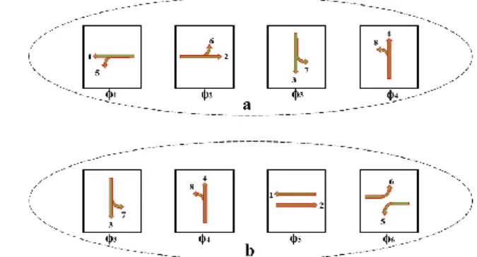
The proposed algorithm relies on a theory of combination without repetition. Two modes of phase configuration for an arterial road are used in this work as illustrated in Fig. 1. The mode 2 is used when the traffic flows from the two opposed directions of the main road approaching an intersection at the same time, otherwise, mode 1 is used. Mode 1 includes ϕ1, ϕ2, ϕ3, and ϕ4 with a 4! = 24 possible combinations. Mode 2 is ϕ3, ϕ4, ϕ5, and ϕ6 with same possible combinations.
The total possible combination of the two modes is 48. There is no need to coordinate the side road corresponding to ϕ3 and ϕ4. Consequently, there is no effect to coordinate the arterial between the sequence of ϕ1 → ϕ2 → ϕ3 → ϕ4 and ϕ1 → ϕ2 → ϕ4 → ϕ3.
Moreover, there is a strict requirement for ϕ5 and ϕ6 to follow each other. Accordingly, the possible combinations are reduced to 26. Definitely, the situation is different when considering an urban traffic network. In addition, these possible combinations are visible phase arrangements for a four edges arterial intersection.
Fig. 1. The phase configuration of proposed method (a) Mode 1 and (b) Mode 2.
The objective here is to perform coordination between neighbouring intersections based on the selection of visible phase arrangement that provides the minimum waiting time, as well as reduces the possibility of vehicles’ stop at the intersection. Many steps followed to implement this algorithm.
Firstly, since the structure of intersections is fixed, the
combination of visible phases is also fixed and can be determined in advance based on (6)
1 2 3 [ , , , ..., ],
p k
C c c c c (6)
where ck is the individual combination within k (visible
phase arrangement).
Secondly, the algorithm searches through the combination
of visible phase arrangements to find the set of phase order that yields the minimum difference between the start of the phase and the remaining time of vehicle (from the preceding intersection) to reach the stop line belonging to phase.
The algorithm uses the following expression to find the set of phase ordering:
1 2 3 [ , , , ..., k],
. . 1| |, m k r i r i i d
p v (8)where m, pr.i, and vr.i are the number of phases at the
intersection, the remaining time of ith phase to turn to green
and the remaining time of the on head vehicle that departed from neighbouring intersection to reach the stop line of ith
phase respectively.
The vr.i is comprised of remaining waiting time at the
neighbouring intersection plus the travel time between the two intersections
.i ,
r i i
v rt tt (9)
where rti represents the remaining time of the corresponding
phase at the preceding intersection to be switch to green signal and tti is the travel time between the preceding and
successive intersections.
The tti is a function of vehicle speed and distances
between intersections . i a l tt S (10)
Although the distance l is fixed, the tti is variable due to
the variability of the average vehicle speed Sa on the edge
depends on the traffic state and is calculated as in (10).
D. The Adjustment of Green Time
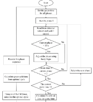
The optimal cycle and phase split are estimated based on the data measured during the previous cycle. The estimated parameters are executed in the current cycle. During the cycle execution, the traffic condition change takes place and that can lead to a difference between the calculated and actual optimal cycles. Fuzzy logic is applied continuously at each cycle to overcome this variation. The steps of performing the proposed algorithm are shown in Fig. 2.
Fig. 2. The flowchart of the proposed method.
The proposed fuzzy logic is intended to adjust the phase green time during its execution. It contains three inputs, namely RQL, FR, and RT_GP and one output denoted by END. The RQL is the Remaining Queue Length for the lane
group of the current green phase. The Flow Rate (FR) is an input that denotes the passing rate of the green phase. The third input denotes the remaining time of the current green phase. The output Extend, No change or Decrease (END) of the fuzzy logic is used to extend, shorten or keep no change the remaining time of the current green phase. Figs. 3–5 below illustrate the memberships of the three inputs, while Fig. 6 illustrates the output of the proposed fuzzy system.
Fig. 3. The remaining queue length fuzzy membership.
Fig. 4. The remaining time of green phase fuzzy membership.
Fig. 5. The flow rate of fuzzy membership.
Fig. 6. The extending, no changing or shortening fuzzy membership. The proposed fuzzy logic system comprises forty-eight fuzzy rules. Some of these rules are illustrated in Table I. There is a risk of starvation for some roads if the fuzzy system extends the current green phase too long. To prevent this phenomenon, the maximum extension of the estimated phase green time is limited by a fixed rate depend on estimated value of the phase. In this work, the rate of 1.4 and the rate of 1.2 for the major and minor roads are
suggested, respectively.
TABLE I. SOME EXAMPLES OF THE FUZZY LOGIC RULES.
R1 If RQL is Short and RT_GP is Short, and FR is Zero, then END is NM
R2 If RQL is Short and RT_GP is Medium, and FR is low, then END
is NS
R3 If RQL is Medium and RT_GP is Long, and FR is High, then
END is Zero
R4 If RQL is Medium and RT_GP is Long, and FR is Medium, then END is NS
R5 If RQL is Long and RT_GP is Short, and FR is Zero, then END
is PM
R6 If RQL is Long and RT_GP is Medium, and FR is Zero, then
END is PS
IV. CYCLIC BACKPRESSURE ALGORITHM
The backpressure algorithm is originally applied to the wireless communication networks to maximize the network throughput [20]. The basic idea of backpressure is to assess the pressure on downstream nodes while determining the traffic control on the upstream node.
In this section, the backpressure method suggested in [21] is discussed to compare it with our proposed method. Commonly in the backpressure algorithm, the road network is modelled as a standard queued network by a directed graph G = (N, J), where N = {N1, N2, N3, …, Nn} is a set of
nodes representing roads with queuing vehicles and J = {j1,
j2, j3, …, jm} is a set of junctions representing the
intersections in the network. It is assumed that there are links at junction ji that provide transfers of vehicles from
node to node in one-to-one connection with an ordered pair of elements in N. The signalized junction is modelled as a local controller to manage the conflicting movement of a junction. For every junction ji, there are I(ji) and O(ji)
indicating the inputs and outputs nodes, respectively. There exists at least a link l ∈ ji pointing from Na input to Nb output
nodes.
Every local controller maintains an internal queue for every input/output nodes, and controller work enables transferring vehicles from an input to an output of the junction. Each junction may serve different combinations of
I(ji) simultaneously in a single phase. Let P = {p1, p2, p3, …,
pk} be the set of all possible phases through a junction ji.
Furthermore, we assume that with every possible movement (Na, Nb) through a junction, there is a rate Xab(t), in which
vehicles can flow through the junction. Xab(t) is equal to the
number of vehicles that can move from node Na to Nb if a
phase pk is activated, where pk ∈ p. Xab(t) and Rbc are
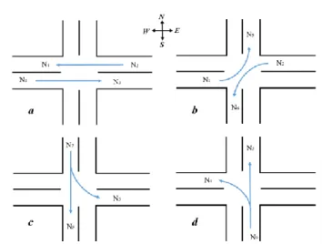
assumed to be known and constant over time based on the simulated traffic flows. Figure 7 illustrates the phase configuration used in four roads intersection in arterial road network under study.
There are two types of vehicle arrival to the intersection in traffic networks. The vehicles can arrive exogenously and/or endogenously at each intersection. A vehicle exogenously enters the network from terminal nodes, then travels along one or more nodes endogenously in the arterial network and leaves the network at a certain node. Vehicle moves endogenously from upstream to the downstream junction. Thus, for each vehicle at the junction, there is an associated entering and exiting pair of nodes. Due to the
routing of vehicles, there are several queues at node Na, and
Qab(t) denotes the number of vehicles at node Na waiting to
leave into node Nb within slot t. The queue at Nb is equal to
( ).
bc
bQ t
Fig. 7. The phase configuration of backpressure method (a) east to west and west to east straight movement, (b) east to south and west to north left-turn movement, (c) north to south straight and north to east left-left-turn movement, (d) south to north straight and south to west left-turn movement.
In the original backpressure, all vehicles queued on Na
generate the pressure of phase p. In the work proposed in [21], the pressure of phase p is generated only by vehicles queued on Na waiting for moving to Nb. Furthermore, it is
different from the original backpressure in such that it is considered as the average queue at downstream node Nb.
The queue length Qab is calculated as the number of vehicles
that stopped at the input node Na∈ I(ji) waiting for moving
to node Nb ∈ O(ji). The average queue at the node is
calculated as bc bc( ),
c C R Q t
where Rbc represents theproportion of the vehicle leaving Nb and entering Nc. As
standard in queuing network control, the time is slotted, and at beginning of each time slot t, the control decision is
determined. Here, the time slot t is equal to cycle time C. The weight at every junction ji for each phase pk ∈ P is
calculated as in (11). It is a difference between queue length
Qab at the input node Na and average queue length
( )
bc bc
c C R Q t
at the output node Nb( ) ( ) ( ) ab c C bc bc , ab a b R Q t Q t W t x x
(11)where xa and xb are the capacity of node Na and Nb,
respectively.
For each phase pk∈P, the total pressure release allowed
by pk is computed by (12)
,
( k) max(0, ab( ) ab( k)).
a b
P p
W t X p (12)It is equal to the sum of weights through each link of the junction weighted by the rate Xab(t). Xab(t) is considered a
saturation rate if Na and Nb belong to pk, and zero otherwise.
The optimization horizon is divided into intervals or cycles of periods C. Within each cycle, there exists Ce(n)
remaining effective green time as in (2). The extra green time is added to the minimum green time calculated proportionally to the pressure of each phase as in (13) and (14): ( ) , ( ) k k p s s p P p F P p
(13) ( ), k k p p e g F C n (14)where Fpk is the fraction of phase pk.
The total green time split of phase pk is calculated as in
(15)
,
k k
p p m
G g G (15)
where the Gpk is the effective green time of phase pk
executed in the next cycle, k represents the number of phases at intersection.
V. SIMULATION AND SCENARIO SETUP
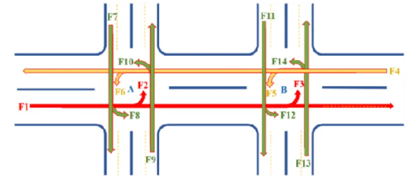
The arterial road network is adopted for two connected intersections as illustrated in Fig. 8. All roads are
bidirectional with four lanes in each direction. The lanes in arterial roads are assigned as following; the most left lane is dedicated for the left turn, the right two lanes are dedicated for the straight movement, and the third lane is sheared between left turn and straight movements. For simplicity, all right turn traffic movements in the road network are considered equal to zero.
There are some assumptions considered to obtain the simulation:
1. The vehicles only enter and exit to/from the arterial road network at edge nodes;
2. All intersections have the same loss time L due to idle times during switching between phases;
3. All intersections have four phases.
The Three different traffic volumes are generated for 3 hours as shown in Table II. F1, F4, F7, F9, F11, and F13 represent the input volumes for the arterial road network. F2, F3, F5, F6, F8, F10, F12, and F14 represent the left turn volumes. For example, in the first hour, the volume from west to east (F1) band of the arterial is 2100 vehicles/hour and the volume from east to west (F4) band is 2000 vehicles/hour.
Fig. 8. The arterial road network under study.
The maximum speed of all vehicles is determined based on the lane maximum speed. The maximum speed of all lanes is set to 50 km/h. The time between two phases (loss time) is set to 3 seconds and represented by the yellow signal for all phases at each intersection.
The tti is considered to be 32 s corresponding to the
400 m distance between two intersections and speed of 50 km/h plus the loss time.
TABLE II: THE APPLIED VOLUMES TO AN ARTERIAL ROAD
Flows F1/ F2/F3 F4/F5/F6 F7/ F8 F9/ F10 F11/ F12 F13/ F14 1st hour 2100/400/400 2000/420/ 420 600/ 400 630/ 420 600/ 400 630/ 420 2nd hour 1050/200/200 1000/210/ 210 300/ 200 315/ 210 300/ 200 315/ 210 3rd hour 1575/300/300 1500/315/ 315 450/ 300 473/ 315 450/ 300 473/ 315 The vehicle that has speed less than 1 km/h is assumed the stopped vehicle. In other word is assumed as the vehicle waiting on the queue.
The total split phase green times (including 3 seconds loss time) for non-optimized fixed time control are set to 20s, 20s, 45s and 15s for ϕ3, ϕ4, ϕ5, and ϕ6 respectively. The cycle time for both a backpressure and fixed time methods is fixed and set to 90 seconds. In the backpressure method, the capacity of the roads is computed based on the lane length
and the vehicle length with a minimum gap between vehicles. The SUMO has a default vehicle length of 5 m and a minimum gap of 2.5 m. As consequence, the capacity of any lane is its length in meters divided by 7.5. The simulation is conducted based on the above condition and the results are obtained.
VI. THE OBTAINED SIMULATION RESULTS
This section is dedicated to comparing the performance of proposed coordinated adaptive fuzzy logic based control methods with a fixed-time traffic control and the cyclic backpressure method.
The proposed methods have been implemented in a widely recognized microscopic, space continuous, and time discrete open source Simulation of Urban Mobility (SUMO) road traffic simulation package
[22]
. SUMO has a lot of supporting tools, such as NETEDIT to edit or build the road networks graphically and NETCONVERT to convert and import road networks from different sources.The number of simulated vehicles for the arterial road network is generated based on Table II. The simulation is performed in a duration of 10800 seconds (3 hours).
During this interval, the 14761 vehicles were passed through the arterial. The simulation results are illustrated in Tables III-V, which represent the average of waiting time, travel time, and speed with their standard deviation,
respectively.
TABLE III. THE AVERAGE WAITING TIME OF ARTERIAL ROAD.
The control method
The average waiting time (second) SD of average waiting time (second) Fixed Time 77.06 68.36 Cyclic Backpressure 63.19 51.37
Isolated Fuzzy Based 52.64 41.44
Coordinated Fuzzy Based 50.70 39.94
TABLE IV. THE AVERAGE TRAVEL TIME OF ARTERIAL ROAD.
The control method
The average travel time (second) SD of average travel time (second) Fixed Time 152.70 110.49 Cyclic Backpressure 130.97 65.62
Isolated Fuzzy Based 119.98 58.92
Coordinated Fuzzy Based 117.80 55.97
TABLE V. THE AVERAGE TRAVEL SPEED OF ARTERIAL ROAD.
The control method
The average travel speed (km/h) SD of average travel speed (km/h) Fixed Time 22.16 10.93 Cyclic Backpressure 22.58 10.11
Isolated Fuzzy Based 24.15 9.38
Coordinated Fuzzy Based 24.60 9.39
Based on the obtained results, it is obvious that the proposed method in both cases over performs the backpressure based and fixed time control methods. Although the isolated fuzzy based method presents a similar average of waiting time compared to coordinated fuzzy based method, its total queue length is longer and with high variation as illustrated in Fig. 9 and Fig. 10.
Fig. 9. The total queue lengths of coordinated fuzzy logic based control method.
Fig. 10. The total queue lengths of isolated fuzzy logic based control method.
The variation of total queue length for the backpressure method is close to the variation obtained from coordinated fuzzy based method. However, its queue length is still long as depicted in Fig. 11. The total queue lengths obtained from the fixed time control method are considered the worst with longest queue and highest variation. Generally, the proposed method outperforms the other methods in terms of average waiting time, travel time, travel speed, and queue lengths.
Fig. 11. The total queue lengths of cyclic backpressure control method.
Fig. 12. The total queue lengths of fixed time control method. VII. CONCLUSIONS
In this paper, a decentralized adaptive signal control strategy based on fuzzy logic and modified Webster optimal cycle formula is proposed. In this strategy, the information, such as traffic demands, the remaining time of coordinated phases, and queue lengths are exchanged between local and neighbouring intersections to maintain coordination between successive intersections. In this work, we attempt to perform the coordination through the reordering the phase sequence to adjust the offset between two intersections. To perform this, the remaining time of coordinated phase and the travel time are used. The proposed methods are compared with fixed time control method and backpressure strategies. The performance enhancement in terms of average waiting time is about 34 % and 18 % compared to the fixed time and backpressure based methods, respectively. The obtained results indicate that our methods in both isolated and coordinated situations present better performance and can be implemented in the real field. To accomplish good results, we recommend that the mathematical model calculating the speed of vehicles based on the existing density of the road must be used instead of fixed travel time.
ACKNOWLEDGMENT
Technical University RAC-LAB and MOSAS group for their valuable technical support to accomplish this work.
CONFLICTS OF INTEREST
The authors declare that they have no conflicts of interest. REFERENCES
[1] J. C. Chedjou and K. Kyamakya, “A review of traffic light control systems and introduction of a control concept based on coupled nonlinear oscillators”, in Recent Advances in Nonlinear Dynamics
and Synchronization. Springer, 2018, pp. 113–149. DOI: 10.1007/978-3-319-58996-1_6.
[2] A. Aljaafreh, N. Al-Oudat, and M. Saleh, “Adaptive traffic-signal control using discrete event simulation model”, International Journal
of Computer Applications, vol. 101, no. 12, pp. 7–12, 2014. DOI:
10.5120/17737-8910.
[3] F. V. Webster, Traffic Signal Settings. London, H. M. Stationery Office, 1958.
[4] A. Y. Zakariya and S. I. Rabia, “Estimating the minimum delay optimal cycle length based on a time-dependent delay formula”,
Alexandria Engineering Journal, vol. 55, no. 3, pp. 2509–2514, 2016.
DOI: 10.1016/j.aej.2016.07.029.
[5] L. Dimitriou, T. Tsekeris, and A. Stathopoulos, “Adaptive hybrid fuzzy rule-based system approach for modeling and predicting urban traffic flow”, Transportation Research Part C: Emerging
Technologies, vol. 16, no. 5, pp. 554–573, 2008. DOI:
10.1016/j.trc.2007.11.003.
[6] D. Andriukaitis, A. Laucka, A. Valinevicius, M. Zilys, V. Markevicius, D. Navikas, R. Sotner, J. Petrzela, J. Jerabek, N. Herencsar, and D. Klimenta, “Research of the Operator’s Advisory System Based on Fuzzy Logic for Pelletizing Equipment”, Symmetry, vol. 11, no. 11, p. 1396, 2019 DOI: 10.3390/sym11111396.
[7] A. C. Soh, L. G. Rhung, and H. M. Sarkan, “MATLAB simulation of fuzzy traffic controller for multilane isolated intersection”,
International Journal on Computer Science and Engineering, vol. 2,
no. 4, pp. 924–933, 2010. DOI: 10.1.1.302.933.
[8] H. Garg and E. G. Kaushal, “Traffic lights control system for Indian cities using WSN and Fuzzy control”, International Research Journal
of Engineering and Technology, vol. 4, no. 7, pp. 2587–2592, 2017.
[9] D. Kermanian, A. Zare, and S. Balochian, “Coordinated signal control for arterial intersections using fuzzy logic”, Open Engineering, vol. 3, no. 3, pp. 436–445, 2013. DOI: 10.2478/s13531-013-0101-1. [10] P. Balaji and D. Srinivasan, “Type-2 fuzzy logic based urban traffic
management”, Engineering Applications of Artificial Intelligence, vol. 24, no. 1, pp. 12–22, 2011. DOI: 10.1016/j.engappai.2010.08.007.
[11] J.-H. Lee and H. Lee-Kwang, “Distributed and cooperative fuzzy controllers for traffic intersections group”, IEEE Transactions on
Systems, Man, and Cybernetics, Part C (Applications and Reviews),
vol. 29, no. 2, pp. 263–271, 1999. DOI: 10.1109/5326.760570. [12] G. Shen and X. Kong, “Study on road network traffic coordination
control technique with bus priority”, IEEE Transactions on Systems,
Man, and Cybernetics, Part C (Applications and Reviews), vol. 39,
no. 3, pp. 343–351, 2009. DOI: 10.1109/tsmcc.2008.2005842. [13] G.-j. Shen and Y.-y. Yang, “A dynamic signal coordination control
method for urban arterial roads and its application”, Frontiers of
Information Technology & Electronic Engineering, vol. 17, no. 9, pp.
907–918, 2016. DOI: 10.1631/fitee.1500227.
[14] S. Hao, L. Yang, L. Ding, and Y. Guo, “Distributed cooperative backpressure-based traffic light control method”, Journal of Advanced
Transportation, vol. 2019, 2019. DOI: 10.1155/2019/7481489.
[15] J. Gregoire, X. Qian, E. Frazzoli, A. de La Fortelle, and T. Wongpiromsarn, “Capacity-aware backpressure traffic signal control”, IEEE Transactions on Control of Network Systems, vol. 2, no. 2, pp. 164–173, 2015. DOI: 10.1109/tcns.2014.2378871. [16] A. Di Febbraro, D. Giglio, and N. Sacco, “A deterministic and
stochastic Petri net model for traffic-responsive signaling control in urban areas”, IEEE Transactions on Intelligent Transportation
Systems, vol. 17, no. 2, pp. 510–524, 2016. DOI: 10.1109/tits.2015.2478602.
[17] A. Jovanović, M. Nikolić, and D. Teodorović, “Area-wide urban traffic control: A Bee Colony Optimization approach”, Transportation
Research Part C: Emerging Technologies, vol. 77, pp. 329–350,
2017. DOI: 10.1016/j.trc.2017.02.006.
[18] J. Gao, Y. Shen, J. Liu, M. Ito, and N. Shiratori, “Adaptive traffic signal control: Deep reinforcement learning algorithm with experience replay and target network”, 2017. arXiv: 1705.02755. [19] S. Chen and D. J. Sun, “An improved adaptive signal control method
for isolated signalized intersection based on dynamic programming”,
IEEE Intelligent Transportation Systems Magazine, vol. 8, no. 4, pp.
4–14, 2016. DOI: 10.1109/mits.2016.2605318.
[20] L. Tassiulas and A. Ephremides, “Stability properties of constrained queueing systems and scheduling policies for maximum throughput in multihop radio networks”, IEEE Transactions on Automatic Control, vol. 37, no. 12, pp. 1936–1948, 1992. DOI: 10.1109/9.182479. [21] A. Kouvelas, J. Lioris, S. Alireza Fayazi, and P. Varaiya, “Maximum
pressure controller for stabilizing queues in signalized arterial networks”, Transportation Research Record: Journal of Transportation Research Board, vol. 2421, no. 1, pp. 133–141, 2014.
DOI: 10.3141/2421-15.
[22] D. Krajzewicz, J. Erdmann, M. Behrisch, and L. Bieker, “Recent development and applications of SUMO-Simulation of Urban Mobility”, International Journal On Advances in Systems and
Measurements, vol. 5, no. 3&4, pp. 128–138, 2012. This article is an open access article distributed under the terms and conditions of the Creative Commons Attribution 4.0 (CC BY 4.0) license (http://creativecommons.org/licenses/by/4.0/).