Selçuk-Teknik Dergisi ISSN 1302-6178 Journal of Selcuk-Technic
Özel Sayı 2018 (ICENTE’17) Special Issue 2018 (ICENTE'17)
Abstract
Design of structures that are inspired by the Nature is gaining attention in the latest year and many studies on the lattices of the materials are being conducted. And for designing, beams and truss structures are widely used elements. Thus, when designing new structures, getting inspired by those lattices and making use of those beams and trusses might prove to be advantageous. Maintaining the estimated lifetime of the structures is also an essential factor. So, it is essential to determine the characteristics of the structures such as the deflection, stresses and more. When determining those structures, finite element analysis can be used effectively. In this study, the lattice inspired models were constructed. Inverted L-frames, inverted U-frames and 3D frames were designed by using those models. Then to analyze those structures, finite elements method was used. The frames were subjected to four different input forces which were generated by using their total weight multiplied by 10, 20, 50, 100 coefficients. The results demonstrated that these designed structures can be used in many areas such as aviation, space, construction. Also, those structures can be used as the core part of the sandwich composites.
Keywords: Lattice of metals, finite element method, dynamic analysis, inspired design
DYNAMIC ANALYSIS OF STRUCTURES WHICH ARE INSPIRED BY LATTICES OF METALS
Serkan GÜLER1, *, Murat YILDIZ1
1Iskenderun Technical University, Faculty of Engineering and Natural Sciences, Department
of Mechanical Engineering, Hatay, Turkey
Selçuk-Teknik Dergisi ISSN 1302-6178 Journal of Selcuk-Technic
Özel Sayı 2018 (ICENTE’17) Special Issue 2018 (ICENTE'17)
METALLERİN KAFES YAPILARINDAN ESİNLENMİŞ YAPILARIN DİNAMİK ANALİZİ
Özet
Son yıllarda doğadan esinlenerek oluşturulan yapıların tasarımı dikkat çekmekte ve malzemelerin kafes yapılarıyla ilgili birçok çalışma yapılmaktadır. Yine bu tasarımlarda kirişler ve kafes sistemler yaygın olarak kullanılan elementlerdir. Bu sebeplerden, yeni yapılar tasarlarken materyallerin kafes yapılarından esinlenmek ve yapı elemanları olarak kiriş ve kafes sistemleri oluşturmak mantıklı olabilmektedir. Yapıların beklenen yaşam sürelerini koruyabilmek de önem verilmesi gereken bir durumdur. Bu sebepten yapılarda meydana gelen deformasyonları, gerilmeleri ve diğer benzeri karakteristik özellikleri tespit etmek bir gerekliliktir ve sonlu elemanlar yöntemi bu özelliklerin analizinde başarılı bir şekilde kullanılmaktadır. Bu çalışmada malzemelerin kafes yapılarından esinlenilerek yapılar modellenmiştir. Bu modeller kullanılarak Tersine L tipi iskelet yapılar, tersine U tipi iskelet yapılar ve 3B iskelet yapılar oluşturulmuştur. Bu iskelet yapılar, kendi ağırlıklarının 10, 20, 50 ve 100 katsayıları ile çarpılarak elde edilen dört farklı etki kuvvetine maruz bırakılmışlardır. Sonuçlardan bu tür yapıların havacılık, uzay, inşaat gibi birçok alanla kullanılabileceğine kanaat getirilmiştir. Ayrıca bu tür yapıların sandviç kompozit yapıların çekirdek kısmında da kullanılabilmesi mümkün görülmektedir.
Anahtar kelimeler: Kafes yapılar, sonlu elemanlar yöntemi, dinamik analiz, esinlenmiş tasarım
1. INTRODUCTION
With constant advancements in technology, new ways are being tested on designing new structures. Thanks to the intriguing engineering systems in nature that researchers have encountered while working on their studies, new structures that are inspired by nature are being designed in the recent years. Lattice-inspired and bio-inspired structures are getting
Selçuk-Teknik Dergisi ISSN 1302-6178 Journal of Selcuk-Technic
Özel Sayı 2018 (ICENTE’17) Special Issue 2018 (ICENTE'17)
popular nowadays and are likely to be applicable in many areas such as construction, aviation, marine, space, and more.
Many studies related to lattices are being carried out. Usage and manufacturing of lattice structures have grown thanks to their lightweight and mechanical efficiency ratio. Lattices that are produced using additive manufacturing are composed of beams [1,2]. In their work, Yan et al. investigated the manufacturability and performance of advanced and lightweight stainless steel cellular lattice structures fabricated via selective laser melting [3]. Mahshid et al. investigated the effect of cellular lattice structures on the strength of workpieces additively manufactured. Authors conducted studies both numerically and experimentally. Numerical studies were performed using DEFORM-3D simulation system based on the finite element method [4]. Lee and McClure developed a numerical model for simulating behaviour of lattice steel tower structures. They presented static large deformation analysis of a lattice steel tower structure using finite element analysis and compared the numerical results with full-scale test. 2-node three-dimensional beam elements proposed in their previous work was used in the static finite element analysis [5]. Guo et al. proposed 3D periodic multilayer lattice materials such as the square, the quadrate, the tetrahedron and the hexagon in order to supply load-carrying necessities of a composite material. Authors obtained static structural simulation results using BEAM189 element in ANSYS, the static mechanical properties of the four multilayer lattice materials were analysed [6]. Sun et al. designed a regular hexahedral unit, produced the lattice structure composed of the Ti–6Al–4V units. After that, they obtained the experimental fracture load and the compression deformation of them through compression tests, then conducted a simulation of the unit and the lattice structure through ANSYS (static) to analyse the failure point [7]. Stankovic et al. developed a generalized optimality criteria method for the optimization of discrete, multimaterial, additively manufactured mesoscale lattice structures for maximum performance in a constrained volume. The generalized optimality criteria method for multimaterial optimization of discrete lattice structure
Selçuk-Teknik Dergisi ISSN 1302-6178 Journal of Selcuk-Technic
Özel Sayı 2018 (ICENTE’17) Special Issue 2018 (ICENTE'17)
continuum model for periodic truss structures suitable for representing long-wavelength wave propagation and verifies it against the full Bloch wave theory and detailed finite element simulations. The FE simulations were run with ALE3D, an arbitrary Lagrangian– Eulerian finite element code developed at Lawrence Livermore National Laboratory [9]. Messner developed a method for optimizing the mesostructure of lattice-structured materials. These materials are periodic arrays of slender members resembling efficient, lightweight macroscale structures like bridges and frame buildings [10]. Syam et al. examined the use of additively manufactured strut-based lattice structures to improve the mechanical vibration isolation properties of a structure. Finite element modelling had been used to determine the theoretical static and dynamic mechanical properties of both the single cell and the array configuration of the lattice structures [11].
Beams and truss structures are common elements in constructing buildings, frame, etc. They are frequently used in the engineering systems [12,13,14,15]. And for analyzing engineering systems, the Finite Element Method (FEM) is a widely used method [15,16,17,18,19,20]. In this method, structures are meshed out and mathematical models which involve differential equations [21] that have huge degrees of freedom are calculated. In the past, equation solving was a difficult task but now that computers are capable enough to process high amount of data in short time, finite element method can be used as the primary solving method [15].
In this study the structures that are inspired by the lattices of materials were designed and analyzed dynamically. For these kinds of structures, suitable designs are important to retain their estimated working life. Hence, it is a must to determine the characteristics of those structures i.e. the deflections, stresses and more. And, the finite element is a capable method to determine those characteristics [15]. So, ANSYS finite element software which featured beam finite elements that are based on the Timoshenko beam theory was used to analyze the structures.
Selçuk-Teknik Dergisi ISSN 1302-6178 Journal of Selcuk-Technic
Özel Sayı 2018 (ICENTE’17) Special Issue 2018 (ICENTE'17)
2. FINITEELEMENTMODELING
There are many materials on the world and four of them were considered. Their lattice structures were inspired by to design the cell models. Those materials are Cu, TiO2,
FeS, ZnSe and their lattice structures are given in Figure 1.
Figure 1. Lattices of the materials: (a) Cu [22], (b) TiO2 [23], (c) FeS [24], (d) ZnSe [25]
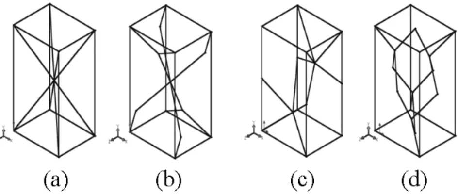
SolidWORKS was used to design the lattice inspired cells and a lattice database was created in IGES format. A labeling style in which the models were named as Li where L is
abbreviation of lattices and i represents the number of the lattices that stored in the database. Those cell models (line models) are given in Figure 2 and their dimensions are given in Figure 3
Selçuk-Teknik Dergisi ISSN 1302-6178 Journal of Selcuk-Technic
Özel Sayı 2018 (ICENTE’17) Special Issue 2018 (ICENTE'17)
Figure 3. Dimensions of lattices and section
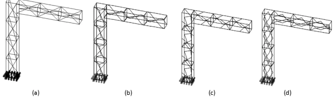
ANSYS is a world-known finite element solving software and thus was preferred in this study. The IGES files that held the cell models were imported into ANSYS. Finite element models of inverted-L, inverted-U frames and 3D frames were constructed by using the cell models. As an example, the inverted L-frames that are composed of L1, L2,L3 and
L4 are given in Figure 4.
Figure 4. L-frames: (a) L1 (b) L2 (c)L3 (d) L4
The finite element models of frames were generated by using only one of the lattice models every time and in whole 12 frames were generated. For the inverted L frames, three models in the direction of the y-axis and two models in the direction of x-axis were used. For the inverted L frames, 4 cell models in the direction of the y-axis and 3 cell models in the direction of x-axis were used. For the inverted U frames, 5 cell models in the direction of the y-axis for the both of the columns were used and 3 cell models were placed in the direction of x-axis to connect them. And in order construct 3D frames, 8 cell models in the direction of the y-axis were used for the columns and 5 and 6 cell models in both of the z-axis and x-z-axis, respectively, to connect those columns together.
b (μm)
1250
h (μm)
2500
t (μm)
1000
s (μm)
50
Selçuk-Teknik Dergisi ISSN 1302-6178 Journal of Selcuk-Technic
Özel Sayı 2018 (ICENTE’17) Special Issue 2018 (ICENTE'17)
BEAM44 elements were used in ANSYS models. BEAM44 is a uniaxial element with tension, compression, torsion, and bending capabilities [26].
The material properties of lattices were defined by pm = [E, ρ, υ, β] where E is
modulus of elasticity (GPa), ρ is density (kg/m3), υ is Poisson’s ratio and β is material damping ratio. pm = [113.8, 4430, 0.342, 0.0001] for TI-6AI-4V material and designing
was constructed as linear elastic isotropic model in this study.
With the intention of accomplishing the finite element models of these frame structures successfully, the modeling macro files were created as a first step. Then, the
solution macro files which are for generating the natural frequencies of the frame structures
were created. In the model macro files, lines were allocated for beams. Afterwards, material properties and section were defined for the beams. Cell dimensions were 1250x2500x1000 µm and assigned section dimensions were 50x50 µm as shown in Figure3. Thus, all lines were meshed out by in according to these sections and material properties. The structures were fixed at points which can be seen over in Figure 5. Lastly, transient dynamic analyses were performed and pulse (impact), step and trapezoidal responses of these frame structures were obtained by using the solution macro files.
3. DYNAMICANALYSISRESULTS
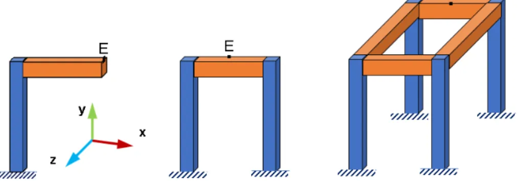
In these analyses, forces were implemented as inputs that are pulse (impact), step and trapezoid forces (see Figure 5) in the direction of z-axis on the “E” point that can be observed in the Figure 6 and from this point the deflection outputs were obtained in the direction of z-axis as well.
Selçuk-Teknik Dergisi ISSN 1302-6178 Journal of Selcuk-Technic
Özel Sayı 2018 (ICENTE’17) Special Issue 2018 (ICENTE'17)
Figure 5. Implemented forces: (a) Pulse (b) Step (c) Trapezoidal
Each frame was subjected to four kinds of input forces which were generated by multiplying their total weight with kf= [10, 20, 50,100] coefficients, respectively. Total
weights of the frames are given in the format of Wi where W means weight and i represents
the number of the frames. The magnitude of forces (Fi) was calculated by using Equation 1.
Fi=kfWi (1)
t is time step of the simulation and ts is simulation time and was calculated by using
Equation 2,
t =1/(20fn) (2)
where fn is natural frequency of the frames at direction of excitation.
In the Figure 5c, ta, tm, and td are acceleration, motion and deceleration time of force
inputs correspondingly.
Selçuk-Teknik Dergisi ISSN 1302-6178 Journal of Selcuk-Technic
Özel Sayı 2018 (ICENTE’17) Special Issue 2018 (ICENTE'17)
For the inverted L-frames, the E point was on the top-middle point on the face that positioned on the free end and oriented towards x-axis. For the inverted U-frames the E point was on the top-middle point on the face that positioned on the horizontal beam and oriented towards z-axis except for L1-U-frames where the E point in the volume center of
the middle cell lattice model. For the inverted 3D-frames the E point was on the top-middle point on the face that positioned on the rear horizontal beam and oriented towards z-axis except for L1-3D-frames where the E point in the volume center of the middle cell lattice
model.
3.1. Results of Inverted L-Frames
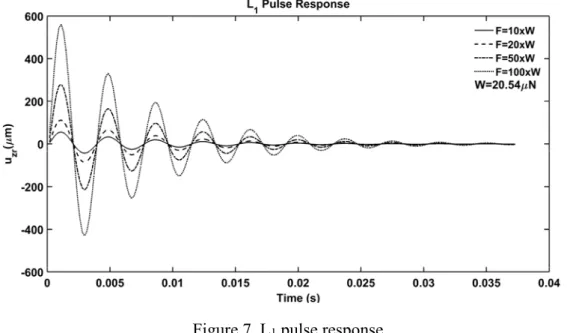
Their weights are given as Wi = [20.54, 20.40, 21,06, 21.13] μN. Pulse, step and
trapezoidal responses of the frames are given in the figs.
Figure 7. L1 pulse response
It can be deduced from the Figure 7 that deflections are 56.06, 112.1, 280.3 and 560.6 µm correspondingly to the applied forces. The maximum deflection of L1-frame was
Selçuk-Teknik Dergisi ISSN 1302-6178 Journal of Selcuk-Technic
Özel Sayı 2018 (ICENTE’17) Special Issue 2018 (ICENTE'17)
Figure 8. L2 pulse response
It can be inferred from the Figure 8 that deflections are 56.83, 113.7, 284.1 and 568.3 µm correspondingly to the applied forces. The maximum deflection of L2-frame was
exhibited at the force that is exact 100 times of its weight.
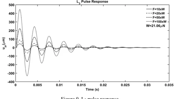
Figure 9. L3 pulse response
It can be shown from the Figure 9 that deflections are 44.7, 89.4, 223.5 and 447.0 µm correspondingly to the applied forces. The maximum deflection of L3-frame was exhibited
Selçuk-Teknik Dergisi ISSN 1302-6178 Journal of Selcuk-Technic
Özel Sayı 2018 (ICENTE’17) Special Issue 2018 (ICENTE'17)
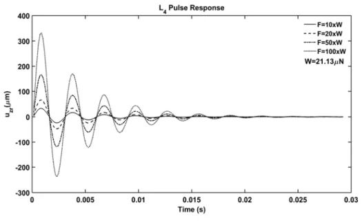
Figure 10. L4 pulse response
It can be shown from the Figure 10 that deflections are 44.7, 89.4, 223.5 and 447.0 µm correspondingly to the applied forces. The maximum deflection of L4-frame was
exhibited at the force that is exact 100 times of its weight.
Figure 11. L1 step response
Selçuk-Teknik Dergisi ISSN 1302-6178 Journal of Selcuk-Technic
Özel Sayı 2018 (ICENTE’17) Special Issue 2018 (ICENTE'17)
Figure 12. L2 step response
It can be seen from the Figure 12 that deflections are 370.3, 740.6, 1852.0 and 3703.0 µm correspondingly to the applied forces. The maximum deflection of L2-frame was shown
at the force that is exact 100 times of its weight.
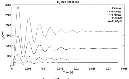
Figure 13. L3 step response
It can be observed from the Figure 13 that deflections are 291.9, 583.7, 1459.0 and
2919.0 µm correspondingly to the applied forces. The maximum deflection of L3-frame was shown at the force that is exact 100 times of its weight.
Selçuk-Teknik Dergisi ISSN 1302-6178 Journal of Selcuk-Technic
Özel Sayı 2018 (ICENTE’17) Special Issue 2018 (ICENTE'17)
Figure 14. L4 step response
It can be observed from the Figure 14 that deflections are 217.9, 435.8, 1090.0 and
2179.0 µm correspondingly to the applied forces. The maximum deflection of L4-frame was shown at the force that is exact 100 times of its weight.
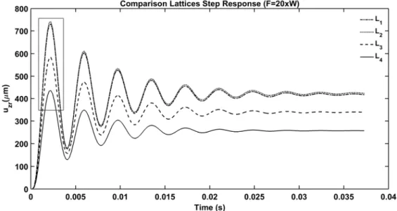
Figure 15. Comparison the step responses of lattices
Selçuk-Teknik Dergisi ISSN 1302-6178 Journal of Selcuk-Technic
Özel Sayı 2018 (ICENTE’17) Special Issue 2018 (ICENTE'17)
According to Figure 16, it is clear that the robust structure is L4-frame due to the fact that it
has the minimum amplitude under the excited force.
Figure 16. Zoomed vie of comparison the step responses of lattices
The trapezoidal inputs were conducted as another excitation type for the structures. The responses were obtained by applying forces that are exact 20 times of their weight. As one can see in Figure 17, L4-frame was the most robust structure, and the results show same
Selçuk-Teknik Dergisi ISSN 1302-6178 Journal of Selcuk-Technic
Özel Sayı 2018 (ICENTE’17) Special Issue 2018 (ICENTE'17)
Figure 17. Comparison the trapezoidal responses of lattices
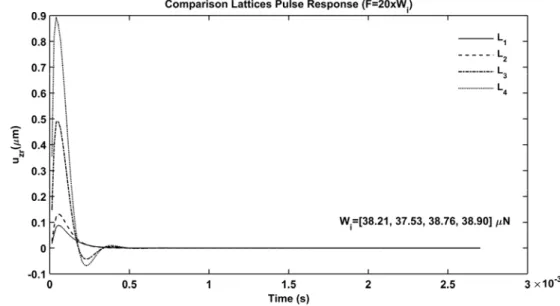
3.2. Results of Inverted U-Frames
Their weights are given as Wi = [38.21, 37.53, 38.76, 38.90] μN. The pulse, step and
trapezoidal inputs were conducted as excitation force type for the structures. Comparison of pulse, comparison of step and comparison of trapezoidal responses of the frames are given in the Figure 18, Figure 19 and Figure 20, respectively.
Selçuk-Teknik Dergisi ISSN 1302-6178 Journal of Selcuk-Technic
Özel Sayı 2018 (ICENTE’17) Special Issue 2018 (ICENTE'17)
Figure 19. Comparison the step responses of lattices
Figure 20. Comparison the trapezoidal responses of lattices
The responses were attained by applying forces that are exact 20 times of their weight. As one can see in Figure 18, Figure 19 and Figure 20, L1-frame was the most
robust structure and the results show same tendency as the other responses as well.
Selçuk-Teknik Dergisi ISSN 1302-6178 Journal of Selcuk-Technic
Özel Sayı 2018 (ICENTE’17) Special Issue 2018 (ICENTE'17)
Their weights are given as Wi = [180.57, 175.89, 181.73, 182.41] μN. The pulse, step
and trapezoidal inputs were performed as excitation force type for the structures. Comparison of pulse, comparison of step and comparison of trapezoidal responses of the frames are given in the Figure 21, Figure 22 and Figure 23, respectively.
Figure 21. Comparison the pulse responses of lattices
Selçuk-Teknik Dergisi ISSN 1302-6178 Journal of Selcuk-Technic
Özel Sayı 2018 (ICENTE’17) Special Issue 2018 (ICENTE'17)
Figure 23. Comparison the trapezoidal responses of lattices
The responses were computed by applying forces that are exact 20 times of their weight. As seen in Figure 21, Figure 22 and Figure 23, L1-frame was the most robust
structure and the results show same tendency as the other responses as well.
4. CONCLUSION
In this work, lattice inspired cell models were generated and by using those cell models, three different structures such as inverted L-frames, inverted U-frames and 3D-frames were constructed in ANSYS software. The 3D-frames were subjected to four different input forces which were their total weight multiplied by 10, 20, 50 and 100 coefficients. The analysis results showed that the frames can withstand to the forces that can be much greater than their own weight.
Still, it is recommended to confirm the results with actual experimental data. As a future study, manufacturing of the designed structures and conducting experimental studies are planned.
Selçuk-Teknik Dergisi ISSN 1302-6178 Journal of Selcuk-Technic
Özel Sayı 2018 (ICENTE’17) Special Issue 2018 (ICENTE'17)
REFERENCES
[1] Chougrani L, Pernot JP, Véron P, Abed S. Lattice structure lightweight triangulation for additive manufacturing. CAD Computer Aided Design 2017; 90: 95–104.
[2] Królikowski M, Grzesiak D. Technological Restrictions of Lightweight Lattice Structures Manufactured by Selective Laser Melting of Metals. Advances In Manufacturing Science And Technology 2014; 38(2): 75-82.
[3] Yan C, Hao L, Hussein A, Young P, Raymont D. Advanced lightweight 316L stainless steel cellular lattice structures fabricated via selective laser melting. Materials and Design 2014; 55: 533–541.
[4] Mahshid R, Hansen HN, Højbjerre KL. Strength analysis and modeling of cellular lattice structures manufactured using selective laser melting for tooling applications. Materials and Design 2016; 104: 276–283.
[5] Lee PS, McClure G. Elastoplastic large deformation analysis of a lattice steel tower structure and comparison with full-scale tests. Journal of Constructional Steel Research 2007; 63: 709–717.
[6] Guo R, Liu R, Jiang W, Chen K, Zhang J, Huang F, Sun X. Numerical Analysis on Static Mechanical Properties of the Periodic Multilayer Lattice Material. Engineering 2011; 3(12): 1149-1154.
[7] Sun J, Yang Y, Wang D. Mechanical properties of regular hexahedral lattice structure formed by selective laser melting. Laser Physics 2013; 23(6).
[8] Stanković T, Mueller J, Egan P, Shea K. A Generalized Optimality Criteria Method for Optimization of Additively Manufactured Multimaterial Lattice Structures. J. Mech. Des. ASME 2015; 137(11): 111405-111405-12.
[9] Messner MC, Barham MI, Kumar M, Barton NR. Wave propagation in equivalent continuums representing truss lattice materials. International Journal of Solids and Structures 2015; 73–74: 55–66.
Selçuk-Teknik Dergisi ISSN 1302-6178 Journal of Selcuk-Technic
Özel Sayı 2018 (ICENTE’17) Special Issue 2018 (ICENTE'17)
[11] Syam, W.P., Jianwei, W., Zhao, B., Maskery, I., Leach, R., 2017, Design of mechanically-optimised lattice structures for vibration isolation, Proceedings of 17th International euspen Conference, Hannover-Germany, 55-56.
[12] Matlock H, Grubbs BR. Development of Methods for Computer Simulation of Beam-Columns and Grid-Beam and Slab Systems. The University of Texas; 1967.
[13] Kiper, G., Soylemez, E., 2009, Deployable space structures, 4th International Conference on Recent Advances in Space Technologies, Istanbul-Turkey, 131-138. [14] Xiang HJ, Shi ZF, Wang SJ, Mo YL. Periodic materials-based vibration attenuation in
layered foundations: experimental validation. Smart Materials and Structures 2012; 21: 112003-112003-10.
[15] Karadeniz H. Stochastic Analysis of Offshore Steel Structures: An Analytical Appraisal. Springer-Verlag; 2012.
[16] Bobby S, Spence SMJ, Bernardini E, Kareem A. Performance-based topology optimization for wind-excited tall buildings: A framework. Engineering Structures 2014; 74: 242–255.
[17] Huang J, Shi Z, Huang W, Chen X, and Zhang Z. A periodic foundation with rotational oscillators for extremely low-frequency seismic isolation: analysis and experimental verification. Smart Materials and Structures 2017; 26: 035061-035061-11.
[18] Ren Y, Yu Y, Zhao B, Fan C, Li H. Finite Element Analysis and Optimal Design for the Frame of SX360 Dump Trucks. Procedia Engineering 2017; 174: 638–647.
[19] Güler S, Karagülle H. Finite element analysis of structures with extruded aluminium profiles having complex cross sections. Latin American Journal of Solid and Structures 2016; 13: 1499–1514.
[20] Wu JJ, Finite element analysis and vibration testing of a three-dimensional crane structure. Measurement 2006; 39: 740–749.
[21] Rao SS. Mechanical Vibrations 3rd Ed. Prentice Hall; 2011.
[22] Isolated 3D model of a crystal lattice of copper, Dreamstime.com, https://thumbs.dreamstime.com/z/isolated-3d-model-crystal-lattice-copper-8059539.jpg [Access Date: 27 June 2017].
Selçuk-Teknik Dergisi ISSN 1302-6178 Journal of Selcuk-Technic
Özel Sayı 2018 (ICENTE’17) Special Issue 2018 (ICENTE'17)
[23] Rutile unit cell 3D balls, Wikimedia.org,
https://commons.wikimedia.org/wiki/File:Rutile-unit-cell-3D-balls.png, [Access Date: 27 June 2017].
[24] Iron (II) sulfide unit cell 3D balls, Wikimedia.org, https://commons.wikimedia.org/wiki/File:Iron(II)-sulfide-unit-cell-3D-balls.png,
[Access Date: 27 June 2017].
[25] Sphalerite unit cell 3D balls, Wikimedia.org,
https://commons.wikimedia.org/wiki/File:Sphalerite-unit-cell-3D-balls.png, [Access Date: 27 June 2017].
[26] ANSYS. Theory Reference for The Mechanical APDL and Mechanical Applications. ANSYS Release 15.0; 2013.