Asymmetric transmission in prisms using
structures and materials with isotropic-type
dispersion
Funda Tamara Gundogdu,1,* Andriy E. Serebryannikov,1,2 A. Ozgur Cakmak,1,3 and Ekmel Ozbay1
1Nanotechnology Research Center - NANOTAM, Bilkent University, 06800 Ankara, Turkey 2Faculty of Physics, Adam Mickiewicz University, 61-614 Poznań, Poland
3Center for Nanotechnology Education and Utilization, Pennsylvania State University, University Park, PA 16802,
USA
Abstract: It is demonstrated that strong asymmetry in transmission can be
obtained at the Gaussian beam illumination for a single prism based on a photonic crystal (PhC) with isotropic-type dispersion, as well as for its analog made of a homogeneous material. Asymmetric transmission can be realized with the aid of refraction at a proper orientation of the interfaces and wedges of the prism, whereas neither contribution of higher diffraction orders nor anisotropic-type dispersion is required. Furthermore, incidence toward a prism wedge can be used for one of two opposite directions in order to obtain asymmetry. Thus, asymmetric transmission is a general property of the prism configurations, which can be obtained by using simple geometries and quite conventional materials. The obtained results show that strong asymmetry can be achieved in PhC prisms with (nearly) circular shape of equifrequency dispersion contours, in both cases associated with the index of refraction 0 and n 1 n . For the 1 comparison purposes, results are also presented for solid uniform non-magnetic prisms made of a material with the same value of n . It is shown in zero-loss approximation that the PhC prism and the ultralow-index material prism ( 0 ) can replace each other in some cases without n 1 affecting the scenario of asymmetric transmission. Moreover, the PhC prism and the solid dielectric prism can show the same scenario at n . 1 Possible contributions of scattering on the individual rods and diffraction on the wedge to the resulting mechanism are discussed. Analogs of unidirectional splitting and unidirectional deflection regimes, which are known from the studies of PhC gratings, are obtained in PhC prisms and solid uniform prisms, i.e. without higher diffraction orders.
©2015 Optical Society of America
OCIS codes: (050.5298) Photonic crystals; (230.5480) Prisms; (120.7000) Transmission; (120.5710) Refraction; (260.2030) Dispersion; (230.1360) Beam splitters.
References and links
1. A. Mandatori, M. Bertolotti, and C. Sibilia, “Asymmetric transmission of some two-dimensional photonic crystals,” J. Opt. Soc. Am. B 24(3), 685–690 (2007).
2. A. E. Serebryannikov, T. Magath, and K. Schuenemann, “Bragg transmittance of s-polarized waves through finite-thickness photonic crystals with a periodically corrugated interface,” Phys. Rev. E Stat. Nonlin. Soft Matter Phys. 74(6), 066607 (2006).
3. A. Cicek, M. B. Yucel, O. A. Kaya, and B. Ulug, “Refraction-based photonic crystal diode,” Opt. Lett. 37(14), 2937–2939 (2012).
4. R. Singh, E. Plum, C. Menzel, C. Rockstuhl, A. K. Azad, R. A. Cheville, F. Lederer, W. Zhang, and N. I. Zheludev, “Terahertz metamaterial with asymmetric transmission,” Phys. Rev. B 80(15), 153104 (2009). 5. J. Shi, X. Liu, S. Yu, T. Vu, Z. Zhu, H. F. Ma, and T. J. Cui, “Dual-band asymmetric transmission of linear
6. J. Xu, C. Cheng, M. Kang, J. Chen, Z. Zheng, Y.-X. Fan, and H.-T. Wang, “Unidirectional optical transmission in dual-metal gratings in the absence of anisotropic and nonlinear materials,” Opt. Lett. 36(10), 1905–1907 (2011).
7. S. Cakmakyapan, A. E. Serebryannikov, H. Caglayan, and E. Ozbay, “Spoof-plasmon relevant one-way collimation and multiplexing at beaming from a slit in metallic grating,” Opt. Express 20(24), 26636–26648 (2012).
8. M. Stolarek, D. Yavorskiy, R. Kotyński, C. J. Zapata Rodríguez, J. Łusakowski, and T. Szoplik, “Asymmetric transmission of terahertz radiation through a double grating,” Opt. Lett. 38(6), 839–841 (2013).
9. C. E. Rüter, K. G. Makris, R. El-Ganainy, D. N. Christodoulides, M. Segev, and D. Kip, “Observation of parity– time symmetry in optics,” Nat. Phys. 6(3), 192–195 (2010).
10. L. Feng, M. Ayache, J. Huang, Y.-L. Xu, M.-H. Lu, Y. F. Chen, Y. Fainman, and A. Scherer, “Nonreciprocal light propagation in a silicon photonic circuit,” Science 333(6043), 729–733 (2011).
11. S. Fan, R. Baets, A. Petrov, Z. Yu, J. D. Joannopoulos, W. Freude, A. Melloni, M. Popović, M. Vanwolleghem, D. Jalas, M. Eich, M. Krause, H. Renner, E. Brinkmeyer, and C. R. Doerr, Comment on “Nonreciprocal light propagation in a silicon photonic circuit,” Science 335(6064), 38 (2012).
12. S. Fan, R. Baets, A. Petrov, Z. Yu, J. D. Joannopoulos, W. Freude, A. Melloni, M. Popović, M. Vanwolleghem, D. Jalas, M. Eich, M. Krause, H. Renner, E. Brinkmeyer, and C. R. Doerr, “Response on Comment on ‘Nonreciprocal light propagation in a silicon photonic circuit’,” Science 335(6064), 38 (2012). 13. D. Jalas, A. Yu. Petrov, M. Eich, W. Freude, S. Fan, Z. Yu, R. Baets, M. Popović, A. Melloni, J. D.
Joannopoulos, M. Vanwolleghem, C. R. Doerr, and H. Renner, “What is — and what is not — an optical isolator,” Nat. Photonics 7(8), 579–582 (2013).
14. A. E. Serebryannikov, A. O. Cakmak, and E. Ozbay, “Multichannel optical diode with unidirectional diffraction relevant total transmission,” Opt. Express 20(14), 14980–14990 (2012).
15. E. Colak, A. E. Serebryannikov, A. O. Cakmak, and E. Ozbay, “Experimental study of broadband unidirectional splitting in photonic crystal gratings with broken structural symmetry,” Appl. Phys. Lett. 102(15), 151105 (2013).
16. S. Xu, C. Qiu, and Z. Liu, “Acoustic transmission through asymmetric grating structures made of cylinders,” J. Appl. Phys. 111(9), 094505 (2012).
17. A. E. Serebryannikov, T. Magath, K. Schuenemann, and O. Y. Vasylchenko, “Scattering of s-polarized plane waves by finite-thickness periodic structures made of ultralow-permittivity metamaterials,” Phys. Rev. B 73(11), 115111 (2006).
18. A. E. Serebryannikov and E. Ozbay, “Unidirectional transmission in non-symmetric gratings containing metallic layers,” Opt. Express 17(16), 13335–13345 (2009).
19. A. E. Serebryannikov, E. Ozbay, and S. Nojima, “Asymmetric transmission of terahertz waves using polar dielectrics,” Opt. Express 22(3), 3075–3088 (2014).
20. T. Xu and H. J. Lezec, “Visible-frequency asymmetric transmission devices incorporating a hyperbolic metamaterial,” Nat. Commun. 5, 4141 (2014), doi:10.1038/ncomms5141.
21. M. Beruete, A. E. Serebryannikov, V. Torres, M. Navarro-Cía, and M. Sorolla, “Toward compact millimeter-wave diode in thin stacked-hole array assisted by a dielectric grating,” Appl. Phys. Lett. 99(15), 154101 (2011). 22. I. Bulu, H. Caglayan, and E. Ozbay, “Highly directive radiation from sources embedded inside photonic
crystals,” Appl. Phys. Lett. 83(16), 3263–3265 (2003).
23. M. Bayindir, C. Kural, and E. Ozbay, “Coupled optical microcavities in one-dimensional photonic bandgap structures,” J. Opt. A, Pure Appl. Opt. 3(6), S184–S189 (2001).
24. B. Temelkuran, E. Özbay, J. P. Kavanaugh, G. Tuttle, and K. M. Ho, “Resonant cavity enhanced detectors embedded in photonic crystals,” Appl. Phys. Lett. 72(19), 2376–2378 (1998).
25. C. Lu, X. Hu, H. Yang, and Q. Gong, “Ultrahigh-contrast and wideband nanoscale photonic crystal all-optical diode,” Opt. Lett. 36(23), 4668–4670 (2011).
26. C. Wang, X. L. Zhong, and Z. Y. Li, “Linear and passive silicon optical isolator,” Sci. Rep. 2(9), 674 (2012). 27. A. Cicek, O. A. Kaya, and B. Ulug, “Refraction-type sonic crystal junction diode,” Appl. Phys. Lett. 100(11),
111905 (2012).
28. C. Wang, C.-Z. Zhou, and Z. Y. Li, “On-chip optical diode based on silicon photonic crystal heterojunctions,” Opt. Express 19(27), 26948–26955 (2011).
29. C. Lu, X. Hu, Y. Zhang, Z. Li, X. Xu, H. Yang, and Q. Gong, “Ultralow power all-optical diode in photonic crystal heterostructures with broken spatial inversion symmetry,” Appl. Phys. Lett. 99(5), 051107 (2011). 30. J. H. Oh, H. W. Kim, P. S. Ma, H. M. Seung, and Y. Y. Kim, “Inverted bi-prism photonic crystals for one-sided
elastic wave transmission applications,” Appl. Phys. Lett. 100(21), 213503 (2012).
31. B. Gralak, S. Enoch, and G. Tayeb, “Anomalous refractive properties of photonic crystals,” J. Opt. Soc. Am. A 17(6), 1012–1020 (2000).
32. X. Ao and S. He, “Negative refraction of left-handed behavior in porous alumina with infiltrated silver at an optical wavelength,” Appl. Phys. Lett. 87(10), 101112 (2005).
33. Q. Wu, E. Schonbrun, and W. Park, “Image inversion and magnification by negative index prisms,” J. Opt. Soc. Am. A 24(10), A45–A51 (2007).
34. K. Oya, T. Nakazawa, S. Kittaka, K. Tsunetomo, K. Kintaka, J. Nishii, and K. Hirao, “Ultrasmall demultiplexer by use of one-dimensional photonic crystal,” Opt. Lett. 30(2), 192–194 (2005).
35. N. Garcia, M. Nieto-Vesperinas, E. V. Ponizovskaya, and M. Torres, “Theory for tailoring sonic devices: diffraction dominates over refraction,” Phys. Rev. E Stat. Nonlin. Soft Matter Phys. 67(4), 046606 (2003). 36. E. D. Palik, ed., Handbook of optical constants of solids, Vol. I (Academic, 1985).
37. B. T. Schwartz and R. Piestun, “Total external reflection from metamaterials with ultralow refractive index,” J. Opt. Soc. Am. B 20(12), 2448–2453 (2003).
38. R. W. Ziolkowski, “Propagation in and scattering from a matched metamaterial having a zero index of refraction,” Phys. Rev. E Stat. Nonlin. Soft Matter Phys. 70(4), 046608 (2004).
39. C. Monzon, D. W. Forester, and P. Loschialpo, “Exact solution to line source scattering by an ideal left-handed wedge,” Phys. Rev. E Stat. Nonlin. Soft Matter Phys. 72(5), 056606 (2005).
40. X. Yu and S. Fan, “Anomalous refraction at photonic crystal surfaces,” Phys. Rev. E Stat. Nonlin. Soft Matter Phys. 70(5), 055601(R) (2004).
1. Introduction
Asymmetric transmission, a Lorentz reciprocal phenomenon that may appear in the structures made of linear, isotropic, passive materials, has extensively been studied in the last decade [1–8]. The interest in this phenomenon has been stimulated by the attempts to find new operation regimes with strong directional selectivity that might be realized with the aid of conventional materials. It can be obtained with the aid of diffraction on volumetric structures [1,2], polarization conversion [4,5], or diffraction on thin structures with slits and corrugations that may support surface waves [6–8]. In other words, asymmetric transmission may appear due to different mechanisms that can lead to the appearance of new transmission channels. Breaking spatial inversion symmetry has been considered as the necessary condition for obtaining such channels.
Strong directional selectivity without breaking time-reversal symmetry can also be obtained in the parity-time framework [9,10]. Sometimes, asymmetric transmission related (reciprocal) effects are mistakenly mixed with optical isolation, a purely nonreciprocal regime, that led to the discussions regarding what is achievable in the reciprocal structures, e.g. see [10–13]. Initially, diffraction inspired asymmetric transmission has often been associated with the nonsymmetric structures known as photonic crystal (PhC) gratings [1,2,14–16] and nonsymmetric gratings made of an ultralow-index material (ULIM) [17–19]. Later, metamaterials have been utilized in order to obtain more compact performances [20,21]. Generally, asymmetric transmission requires different coupling conditions at the front-side and the back-side incidence and, in particular, the possibility of blocking some of the transmission channels that depends on the side of illumination. Wideband blocking of transmission through some of the channels can be achieved in the grating-type structures due to specific properties of PhCs and ULIMs. It is connected with the ability of PhCs to modify the dispersion properties and, thus, control propagation of electromagnetic waves in certain directions that has been the focus of interest since 90s [22–24].
PhC prisms represent another big class of the structures, in which either geometrical features or simultaneously geometrical and dispersion features allow one obtaining the strongly pronounced asymmetric transmission [3,25–30]. In these structures, the possibility of choosing directions of the prism interfaces gives an additional degree of freedom, while the contribution of higher diffraction orders to the resulting mechanism is generally not required. The emphasis has been put on the operation regimes connected with the effect of anisotropic-type dispersion of the Floquet-Bloch modes for one or both of the stacked PhC prisms. In particular, diodes based on stacks of two PhC prisms with different dispersion properties have been proposed [3,25]. At the same time, from the studies of nonsymmetric gratings, it is well known that strong asymmetry is also possible at simpler, i.e. isotropic-type dispersion, if equifrequency dispersion contours (EFCs) are narrower than in air. This remains true for both PhC and ULIM based nonsymmetric gratings [17–19,21]. It is noteworthy that in PhC gratings and prisms dispersion of isotropic and anisotropic type can co-exist in the neighboring bands, enabling different regimes of directional selectivity and, thus, opening a perspective route to multifunctional devices. The ULIM based structures promise some advantages like ultra-wideband one-way transmission [19]. However, in contrast with the PhC based structures they do not allow obtaining different regimes of directional selectivity in one configuration. Moreover, the problem of losses can be significant when ULIMs are used, since these artificial materials contain metallic components. Hence, PhC prisms that utilize the bands with isotropic-type dispersion invoke a detailed study, whereas results for
ULIM prisms might be useful for the comparison purposes. This is reasonable also because the other regimes, which have been already demonstrated in PhC prisms, like superprism and negative refraction, might be obtained in the same structure, e.g. see [31–34].
In this paper, we study diffraction on the prisms based on two-dimensional PhCs in the operation regimes connected with isotropic-type dispersion. The emphasis will be put on demonstration of the general concept. It will be shown that a strong difference between the forward- and backward-incidence cases can be achieved for a sole PhC prism when EFCs correspond to a small positive (ultralow) index of refraction, 0 . In order to clarify the n 1 dominant physics in the scenarios of asymmetric transmission observed in PhC prisms, comparison will be done with the solid uniform prisms that are made of a non-magnetic ULIM with the same value of n as that obtained from the EFC analysis for the PhC.
Moreover, strong asymmetry in transmission will be demonstrated for sole (not stacked) PhC prisms and sole solid prisms for EFCs corresponding to a positive index larger than unity. In particular, the appearance of asymmetric transmission in solid prisms made of a dielectric material with n will be demonstrated. In contrast with the known PhC prism based 1 structures for asymmetric transmission, in which a stack of two different prisms and anisotropic-type dispersion are utilized, we demonstrate here that strong directional selectivity can be obtained using a single prism and isotropic-type dispersion. Furthermore, incidence on the prism corner (wedge) will be exploited as an important counterpart of the resulting mechanism, when the opposite incidence direction corresponds to the middle of its longer interface. The possible effects of periodicity of the PhC prism interfaces and suppression of refraction by other phenomena will be discussed. In [35], it has been shown by Garcia et al. that diffraction at the edges can dominate over refraction in a finite-size acoustic crystal being a few wavelengths large. In our case, zero-order refraction and reflection remain the basic effects leading to the desired asymmetry in transmission. For the sake of definiteness, we consider under asymmetric transmission directional selectivity arising in a multichannel (multiport) transmission system, so that 90 bending rather than transmission
through the prism from one half-space to another is sufficient. Simulation results are obtained for the Gaussian-beam incidence on the prism shaped structures by using the Finite-Difference Time-Domain (FDTD) method through Lumerical, a commercial software program that is especially appropriate for simulations of optical structures. CST Microwave Studio, a solver based on the finite integration method, has been used to calculate the dispersion of Floquet-Bloch modes of the PhC.
2. Results and discussion
2.1 Directional selectivity at the inclined interface
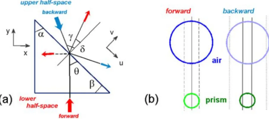
Schematics showing the basic features of the prism geometry and asymmetry in coupling at the forward-case and backward-case illumination are presented in Fig. 1. Possible directions of the outgoing transmitted and reflected beams are shown in Fig. 1(a) in the case when EFCs for the prism are narrower than for the surrounding air, as occurs at 0 . Throughout the n 1 paper, we assume that 45. For the purposes of numerical study, we also assume
that 45, i.e. the forward-case and the backward-case illumination directions are opposite
to each other. However, may be not fixed when analytical estimates are investigated.
stands for the angle of deflection of the outgoing beam (at the forward-case illumination) from the normal to the exit (here - inclined) interface.
The principal difference in coupling at the inclined interface in these two cases is demonstrated in Fig. 1(b). At the forward-case illumination, the wave is incident from the prism side, so that it should be coupled to the outgoing wave in air at any incidence direction, see the left plot in Fig. 1(b). Hence, the coupling of the wave incident at 45 is ensured. At
near-zero tangential wave numbers ( kU) may be coupled to a wave propagating inside the prism,
see the right plot in Fig. 1(b). Thus, the wave incident from air on the inclined interface at 45 is either coupled or not, depending on the prism performance. If coupling is possible only at the forward-case illumination, asymmetric transmission takes place. Note that the EFCs for the prism may have a non-circular shape in (kU,kV)-plane, but they must be
narrower than in air. On the other hand, the asymmetric regimes achievable for the circular EFCs look more interesting, because they can be realized by using conventional isotropic materials.
The prism configurations, which are the focus of this paper, represent either a PhC prism or a solid uniform prism made of a material with 0 . The considered PhC prisms n 1 consist of the rods made of a dielectric material with permittivity 11.4 on air background. In fact, they represent the finite-extent structures based on the same infinite PhC. Thus, the different scenarios of asymmetric transmission that are presented in this paper can be obtained in one configuration, but within different frequency ranges, which may correspond to either the same or different Floquet-Bloch modes of the infinite PhC. The rods are arranged in a square lattice with the lattice constant a µm. The diameter of the dielectric rods is 1
0.4
d µm. These values are kept constant throughout the paper. The structure is assumed to be illuminated by the s-polarized Gaussian beam, i.e. electric field vector is oriented along the rod axes for the PhC prisms and along the corresponding direction for the solid prisms. Furthermore, we refer to the PhC prism interfaces that are obtained by cutting a PhC along ΓX and ΓM directions of the first Brillouin zone as the ΓX and ΓM interfaces. These interfaces have periods of L a and L 2a, respectively.
Fig. 1. Schematics of (a) prism configuration illuminated from the lower and the upper half-space; thick and thin arrows - directions of the incident and outgoing beams, respectively; (b) coupling scenarios at the inclined interface illuminated from the prism side (forward case) and from the upper (air) half-space (backward case); circles - EFCs in (kU,kV)-plane; straight lines – examples of construction lines: solid lines - coupling is possible, dashed lines - coupling is formally possible in the limiting case, and dotted lines - coupling is impossible.
In the simulations, we use the value of 11.4 for the rods. It is taken from the range, to which several materials applicable at the infrared do belong. Si is commonly used for fabrication that is the fundamental step in realization of practical devices. This material has the permittivity of 11.76 to 12.11 at the frequency range that extends from 50THz to 215THz (wavelength of 6 µm to 1.4 µm) [36]. It may be considered as a real material for all the cases presented in this paper. Si is (almost) lossless in the frequency range extending from 64THz to 209THz, which corresponds to our designs. Thus, the use of zero-loss approximation in simulations is possible. Besides, GaAs ( 10.24-11.42 at 50THz-215THz) and InP ( 9.48-10.11 at 50THz-215THz) [36] may also be considered as possible options for future fabrication. Since results for solid uniform prisms should be used only for the comparison
purposes, we do not consider here details of performance of the corresponding artificial materials.
2.2 Case of very narrow equifrequency dispersion contours at 0 n 1
First, we consider the case corresponding to lower-frequency part of the fourth lowest band of the PhC, where EFCs show a nearly circular shape and are substantially narrower than in air, see Fig. 2(e). In particular, the value of n0.22 corresponds to f 179THz (ka3.75,
/
k c). Depending on whether magnetic properties are shown by the PhC or not, the considered PhC may be associated with (but are not equivalent to) either ULIM with the same value of n [37] or epsilon-near-zero (ENZ) material with 0.05 [38]. It is noteworthy that ULIMs represent a more general class of artificial materials that also includes ENZ materials. Thus, we also consider the case of a solid uniform prism made of a homogeneous material with n0.22. For such a prism, ultrarefraction is expected to appear similarly to one of the
cases studied in [31]. To demonstrate the basic features of asymmetric transmission, we first consider the case when the longer side (hypotenuse) and the shorter sides of the PhC prism represent ΓX and ΓM interfaces, respectively. The PhC prism is illuminated normally to the lower (here - ΓM) interface in the forward case and at the angle of 45 to the upper (here - ΓX) interface in the backward case.
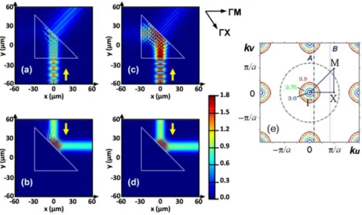
Fig. 2. Electric field distribution at 179 THz (ka3.75): for PhC prism at (a) forward-case (here - ΓM interface) illumination and (b) backward-case (here - ΓX interface) illumination, and for non-magnetic ULIM prism with n0.22 at (c) forward-case (here - shorter-side) illumination and (d) backward-case (here - longer-side) illumination; yellow arrows in plots (a)-(d) show directions of beam incidence; (e) EFCs in (kU,kV)-plane and construction lines: solid lines - EFCs for PhC at ka3.6 (dark-blue line), ka3.675 (blue line), ka3.75 (green line), ka3.825 (orange line), ka3.9 (brown line); dashed circle - EFC for the surrounding air at ka3.75; A and B - construction lines at ka3.75 for the inclined interface in forward case and backward case, respectively.
Results for field distribution, which are obtained at the Gaussian beam illumination, are presented in Fig. 2. In the forward case in Fig. 2(a), the injected beam refracts at the exit interface according to Snell's law that leads to the outgoing beam propagating in quasi-normal direction, i.e. arcsin( sin ) 8.9n . Generally, coupling always occurs for transmission
from the medium with a smaller value of n to the medium with a larger value of n , see the left plot in Fig. 1(b) and Fig. 2(e). Thus, a Floquet-Bloch mode of the PhC is coupled to the outgoing wave in the forward case. In the backward case in Fig. 2(b), perfect rightward reflection is observed, since the maximal angle of incidence (with respect to the incidence interface), at which coupling would be possible at n0.22, is max12.7. This is substantially smaller than the incidence angle of 45, see Fig. 2(e). Hence, there is no
transmission from the upper to the lower half-space, whereas the forward-case transmission is accompanied by the deflection of the outgoing beam. Thus, asymmetry in transmission is
evident. This scenario is associated with single-beam unidirectional deflection, a regime that
has earlier been studied in PhC gratings [14], ULIM gratings [18,19], and metamaterial slabs with one-side corrugations [21]. In contrast with the above-mentioned structures, in the studied prisms this regime is obtained without new transmission channels. It appears only due to inclining the ΓX interface. Clearly, the absence of coupling of zero and higher orders at the inclined interface in the backward case can be considered as the necessary condition of
asymmetric transmission. However, although asymmetry can also appear when the backward-case transmission is not vanishing, this backward-case looks less interesting than that in Fig. 2.
The scenario observed in the field maps in Figs. 2(a) and 2(b) is in good agreement with predictions based on the analysis of EFCs and construction lines shown in Fig. 2(e). Indeed, the construction line denoted by A crosses the EFCs of the PhC and air, leading to coupling and, thus, quite strong field above the prism. In turn, the construction line denoted by B does not cross the EFC of the PhC and, hence, there is no coupling and no field inside the prism. It is noteworthy that 0 n 0.4 in the ka -range used in Fig. 2(e).
Clearly, coupling of the wave incident from the upper half-space could be obtained by choosing the periodicity of the inclined interface such that the order m is coupled. The 1 minimal value of SL a/ , at which such a coupling is possible at fixed values of ka , , and n (i.e. at least if the outgoing wave has the diffraction angle of / 2) is given by
)]Smin2/[ka(sinn . (1) In turn, the minimal among the possible values of Smin is formally achieved at / 2, so
that )] 1 ( [ 2 min / ka n S . (2)
At ka3.75 and n0.22, Eq. (2) gives Smin1.37. To compare, for a ΓM interface, we have L 2a and, hence, S 2. Thus, coupling may occur in the considered case for the ΓM interface, provided that angle of incidence is large enough (also when 45). In turn,
for 45, Eq. (1) leads to 181 2
min .
S , i.e. a larger corrugation period is required than that of the ΓM interface. Finally, the downward propagation of the beam inside the PhC prism owing to the coupling of the order m at 1 45 in the backward case requires that
3.04 )] 1 ( sin [ 2 min minS~ / ka n
S . Moreover, this order will be the sole coupled order for 45, if sin (1 n)n(sin . Note that the above given estimates are obtained from 1)
a simple analysis of the EFCs, but its details are omitted here.
To compare, Figs. 2(c) and 2(d) present the results for a solid prism made of an ULIM with n0.22. Clearly, higher diffraction orders cannot appear in this case, because the interfaces are not corrugated. The comparison of Fig. 2(a) with Fig. 2(c) and Fig. 2(b) with Fig. 2(d) shows that the number and directions of the outgoing beams are the same. This means that refraction and reflection remain the basic effects, while scattering on the individual rods and diffraction on the entire structure insignificantly contribute to the
resulting mechanism of directional selectivity. Note that the ultrarefraction scenario in Figs. 2(a) and 2(c) is, in fact, the same as that shown in Fig. 11, in [31], where it has not been considered in connection with asymmetric transmission. It is important that the outgoing beams at the forward-case and the backward-case illumination do not interfere with each
other, i.e. two processes are entirely independent. This feature is expected to be general for
asymmetric transmission. Earlier, such independence of two processes has been found in the PhC gratings [14] and thin metallic gratings with a slit that may support surface waves [7]. For the prisms, it can be obtained without higher diffraction orders and surface waves.
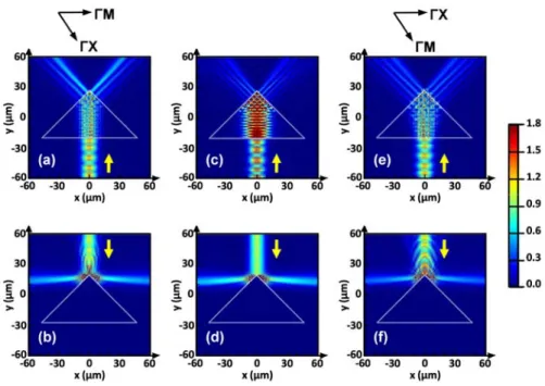
Fig. 3. Electric field distribution at 179 THz (ka3.75): for PhC prism at (a) forward-case (here - ΓM interface) illumination and (b) backward-case (wedge) illumination; for non-magnetic ULIM prism with n0.22 at (c) forward-case (here – longer-side) illumination and (d) backward-case (wedge) illumination; for PhC prism at (e) forward-case (ΓX - interface) illumination and backward-case (wedge) illumination; yellow arrows show directions of beam incidence.
Now, we change the PhC prism structure so that the longer and shorter sides have the ΓM and ΓX interfaces, respectively. Such a structure is obtained by stacking two prisms from Fig. 2 along one of their shorter sides. The second modification compared to Fig. 2 concerns incidence for the both PhC and ULIM prisms. Now, the Gaussian beam is incident in the forward case at the middle of the ΓM interface, while the backward-case illumination corresponds to the 90 corner between the shorter sides of the prism. This modification can
be considered as the shift of the illumination area while stacking two identical prisms as proposed above. The results are presented in Fig. 3. The field distribution looks very similar to the case when two field maps from Figs. 2(a)-2(d) would properly be combined in line with that how the corresponding prisms are stacked. Accordingly, the asymmetric transmission scenario differs from that in Fig. 2, whereas the dominant role of reflection and refraction in the resulting mechanism remains. Indeed, similarly to Fig. 2, all directions of the outgoing beams for the two opposite incidence directions do not coincide, being mainly determined by Snell's law. This enables the co-existence of two processes in two virtual multichannel circuits that may operate independently of each other. Although diffraction at the wedge is weak, fine structure of the outgoing waves can be affected by internal reflections from the left and right shorter side of the wedge. There are no qualitative differences between the cases of
PhC prism in Figs. 3(a) and 3(b) and ULIM prism in Figs. 3(c) and 3(d). It is noteworthy that dual-beam splitting with the angle between the beams that is close to 180 can be realized at
the backward-case (wedge) illumination. To compare, Figs. 3(e) and 3(f) present the field distribution in the cases, which differ from Figs. 3(a) and 3(b) only in that the longer and the shorter sides of the PhC prism now have ΓX and ΓM interfaces, respectively. From the comparison of Fig. 3(a) with Fig. 3(e) and Fig. 3(b) with Fig. 3(f), it follows that there is not important how the interfaces are located with respect to the Brillouin zone boundaries. This is, however, quite expectable, because higher diffraction orders remain evanescent and do not affect the number and directions of the outgoing beams.
2.3 Case of moderately narrow equifrequency dispersion contours at 0 n 1
Next, let us consider the frequency range, in which EFCs of the PhC can be close to circular ones but simultaneously take new features that indicate disappearance of a pure isotropic-type dispersion. This occurs, for instance, for the same PhC and the same band as in Figs. 2(a), 2(b), 3(a) and 3(b) but at larger frequencies. For example, at f 207THz (ka4.335), nearly circular EFCs are located around Γ-point, but additional, smaller circular contours are located around M-point, see Fig. 4(e). Thus, both the former and the latter may contribute to the coupling. The value of n0.59 is obtained from the width of the EFC around Γ-point at
4.335
ka , while the effect of the small EFC near M-point is ignored. Thus, the full equivalence between the PhC prism and the ULIM prism is not achieved in this case. Note that the cases of n0.22 and n0.59 might be not obtainable in one ULIM prism at the same frequencies as for the PhC prism. The results for the PhC prism at ka4.335 and for the ULIM prism at n0.59 are presented in Fig. 4.
The maximal angle of incidence (with respect to the normal to the illuminated interface), at which coupling of the incident beam to a wave propagating inside a prism is possible at
0.59
n , is max36.2. For the PhC prism, coupling is also possible within a narrow
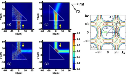
frequency range at larger values of , which correspond to the small EFC around M-point. Asymmetric transmission in Fig. 4 is well pronounced for both the PhC prism and the ULIM prism. However, on contrary to the case of n0.22 in Fig. 2, the scenarios observed for these two structures show significant differences. In case of the PhC prism in Figs. 4(a) and 4(b), the incident beam injection into the prism occurs due to the EFC located around Γ-point in the forward case [see the construction line A in Fig. 4(e)] and due to that around Μ-point in the backward case [see the construction line B in Fig. 4(e)]. However, scattering on the rods results in that the field is spread over a wide area inside the PhC prism. This behavior is associated with an open resonator. In the backward case, it leads to that the zero-order beam reflected at the ΓX interface is the sole outgoing beam, while there is no outgoing beam in the forward case. Thus, asymmetry appears in the considered multichannel transmission system without transmission through the prism.
In the case of the ULIM prism, the scenario is different. It might look like that the differences between Figs. 4(a) and 4(c), on one hand, and between Figs. 4(b) and 4(d), on the other hand, are connected with the small EFC around M-point. However, this EFC can affect penetration into the PhC prism only in the backward case in Fig. 4(b). In turn, in the forward case in Fig. 4(a), the field is spread inside the prism only due to scattering on the rods, because the EFC located around Γ-point should provide coupling at both incidence and exit (inclined) interfaces. At the same time, in the forward case in Fig. 4(c), we observe transmission from the lower to the upper half-space, similarly to Fig. 2(c). Since the incident beam characteristics are kept the same, the observed differences between Figs. 4(a) and 4(c) cannot be explained in terms of a finite angular spectrum. Moreover, in Fig. 4(c), there is no significant reflection from the inclined interface. Hence, the asymmetry manifestations strongly depend on whether the PhC prism or the ULIM prism is considered.
Fig. 4. Electric field distribution at f 207THz (ka4.335) for PhC prism at (a) forward-case (here - ΓM interface) illumination and (b) backward-forward-case (here - ΓX interface) illumination, and for non-magnetic ULIM prism with n0.59 at (c) forward-case (here – normal, shorter-side) illumination and (d) backward-case (here – inclined, longer-side) illumination; (e) EFCs in (kU,kV)-plane and construction lines: solid lines - EFCs for PhC at
25 4.
ka (dark-blue line), ka4.3 (blue line), ka4.335 (green line), ka4.375 (orange line), ka4.425 (brown line); dashed circle - EFC for the surrounding air at ka4.335; A and B - construction lines at ka4.335 for the inclined interface in forward case and backward case, respectively.
According to Eq. (1), coupling of the order m may occur at 1 ka4.335, 45,
and n0.59 when Smin1.12. The downward propagation of the beam inside the PhC prism owing to the coupled order m at 1 45 requires that
5 )] 1 ( sin [ 2 min minS~ / ka n
S . Note that 24.7 in the forward case when 45.
In turn, the beam incident from the upper half-space can be coupled only at 36.2. This
comparison illustrates that the PhC prism and ULIM prism cannot always replace each other, even if higher diffraction orders are evanescent and zero-loss approximation is applied.
Next, Fig. 5 presents the results for the PhC prism and the ULIM prism at f 207THz (ka4.335), when the longer and shorter sides of the PhC prism are associated with ΓX and ΓM interfaces, respectively. For the solid ULIM prism, we again take n0.59. Similarly to Figs. 2 and 3, the PhC prism in Figs. 5(a) and 5(b) is obtained by stacking two half-prisms from Figs. 4(a) and 4(b) along one of their shorter sides, while the illumination area is shifted. Accordingly, all the features observed in Figs. 5(a) and 5(b) are inherited from Figs. 4(a) and 4(b). In particular, the open-resonator type field distribution in Figs. 5(a) and 5(b), blocked transmission in Fig. 5(b), and two symmetrically outgoing beams in Fig. 5(a) should be noticed. A detailed analysis that is required to fully understand all details of the possible effect of the wedge is beyond the scope of this paper. In this concern, the studies of diffraction on the left-handed material wedge [39] and total internal reflection at the inclined interface of the PhC [40] should be mentioned and suggested for the use as entry point. Since higher diffraction orders do not contribute to the asymmetric transmission in Figs. 5(a) and 5(b), the use of ΓX and ΓM interfaces at the longer side and the shorter sides of the PhC
prism, respectively, does not lead to a change in the number and directions of the outgoing beams (not shown), like in the situation illustrated in Fig. 3 for a smaller value of ka .
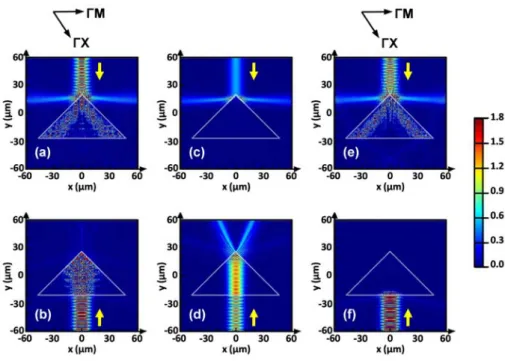
Fig. 5. Electric field distribution for (a) backward-case (here - wedge) illumination and (b) forward-case (here - ΓM interface) illumination for PhC prism at 207 THz (ka4.335); (c) backward-case (here - wedge) illumination and (d) forward-case (here – normal, longer-side) illumination for non-magnetic ULIM prism with n0.59 at 207 THz; (e) and (f) same as (a) and (b) but at 209 THz (ka4.4); yellow arrows show directions of beam incidence.
Similarly to the case of the PhC prism, the basic features observed for the ULIM prism in Figs. 5(c) and 5(d) are inherited from the stacked ULIM half-prisms, see Figs. 4(c) and 4(d). Correspondingly, transmission through the prism occurs only in the forward case. Variations in frequency may lead to a significant modification of the EFC, coupling, and field distribution, although the resulting scenario of asymmetric transmission remains the same. An example is presented in Figs. 5(e) and 5(f) for the same PhC prism as in Figs. 5(a) and 5(b) at
209
f THz (ka4.4). One can see that the only significant difference compared to the case of ka4.335 is that now there is no significant field inside the prism at the forward-case illumination.
2.4 Case of moderately narrow equifrequency dispersion contours at n 1
Finally, we consider the case when the EFCs of the PhC are circular but wider than in air, i.e., they correspond to a dielectric with n , see Fig. 6. For the PhC prism, the case of 1 n 1 can be obtained, for instance, at the upper edge of the lowest band. Field distribution is presented in Fig. 6 for f 64THz (ka1.34), at which the EFCs of the PhC correspond to
1.68
n , while /a 0.213 and /d 0.085. Accordingly, the solid uniform prism is assumed to be made of a dielectric material with n1.68.
Fig. 6. Electric field distributions at 64 THz (ka1.34): for PhC prism at (a) forward-case (here - normal, ΓX interface) illumination and (b) backward-case (here - wedge) illumination, and for solid dielectric prism with n1.68 at (c) forward-case (here - normal, longer-side) illumination and (d) backward-case (here - wedge) illumination; yellow arrows show directions of beam incidence; (e) EFCs in (kx,ky)-plane and construction lines: solid lines - EFCs for the PhC at ka1.1 (dark-blue line), ka1.225 (blue line), ka1.34 (green line),
45 1.
ka (orange line), ka1.575 (brown line); dashed circle - EFC for the surrounding air at 34ka1. ; A and B - construction lines at ka1.34 for the inclined interface in forward case and backward case; thick straight dashed line schematically shows the inclined (here - ΓM) interface at x0.
It is seen that transmission through the prisms tends to vanish in the forward case, while two symmetrically outgoing beams appear in the backward case. Thus, asymmetry in transmission is evident. There is no principal difference in the field maps for the PhC prism and the solid dielectric prism. In the backward case, refraction at the sides of the wedge is the main effect contributing to the resulting mechanism. For the PhC prism, scattering on the individual rods and diffraction on the wedge are not expected to contribute significantly. This is a reason why two identical beams appear inside the prism. Each of the beams is connected with a part of the illuminated area at either the right or the left side of the wedge. At the exit interface, the angular separation of the two beams is enhanced, because the exit medium (air) is less dense. In terms of the beam directions, the scenario observed in Fig. 6 looks identical to transmission-mode unidirectional splitting that has been studied earlier for the nonsymmetric PhC gratings [14,15]. However, now higher orders do not contribute, whereas asymmetry in transmission is achieved due to orientation of the prism interfaces. In the forward case in Figs. 6(a) and 6(c), the incident beam penetrates into the prisms but is very weakly transmitted to the upper half-space. Indeed, transmission is blocked owing to the (nearly) total internal reflections at the wedge [40]. In fact, reflections from the wedge's left and right sides lead to that the beam energy can be directed back to the source. Analysis of reflections at the wedge is omitted here. It is noteworthy that for the PhC prism refraction and reflection features, which are observed at the wedge for both forward-case and backward-case illumination, are in good agreement with the predictions based on the EFCs results, see Fig. 6(e). Indeed, since the construction line A crosses the EFC for the PhC but does not cross the EFC for air, there is no coupling at the inclined interfaces in the forward case. In turn, the construction line B crosses the EFCs for both the PhC and air that enables coupling at the parts of the inclined interfaces, which are located near the wedge, in the backward case.
3. Conclusions
To summarize, we studied directional selectivity arising when the Gaussian beam is incident on a single PhC prism and a single solid uniform prism at two opposite directions. Compared to the earlier studies of asymmetric transmission in prism based configurations, incidence on the corner (wedge) was utilized as a counterpart of the considered mechanism, in which refraction and reflection play the main role. The scenarios of asymmetric transmission for the prisms based on a PhC with nearly circular EFCs that correspond to the index of refraction 0 and on an ULIM with the same value of n can be identical. On the other hand, it n 1 can be possible that substantial differences between two prisms regarding field distribution and directional selectivity can appear, when EFCs (slightly) differ and/or scattering on the rods comes into play. The studied scenarios of asymmetric transmission are affected by neither diffraction on the prism wedges nor higher diffraction orders. In particular, the regimes of unidirectional splitting and single-beam unidirectional deflection, which have earlier been studied in the nonsymmetric PhC gratings in the context of the diffraction inspired mechanism of asymmetric transmission, can be obtained in the prism configurations without contribution of higher diffraction orders. Thus, corrugations in the gratings and inclining interfaces in the finite-size prisms can play the same role. What is even more interesting is that the strongly pronounced asymmetry in transmission can be obtained in the PhC prisms when nearly circular EFCs correspond to n , and in the solid uniform prisms 1 made of a dielectric with the same value of n . The obtained results show that Snell's law can be a powerful tool for the qualitative analysis of asymmetric transmission. Different scenarios of asymmetric transmission can be obtained within different bands in one PhC prism, or even within the different parts of the same band. These bands may include those with isotropic-type and anisotropic-isotropic-type dispersion. Generally, PhC prisms might show a wider variety of the operation regimes than uniform prisms. It is noteworthy that all the effects studied in this paper are realized for simple geometries by using quite usual materials. In spite of that nonreciprocal effects cannot be obtained in the framework of the used mechanism, the possibility of obtaining strong directional selectivity is evident. Since zero-loss approximation has been utilized, the PhC prisms that consist of Si or GaAs rods can be rescaled for lower operation frequencies. The next step toward practical realization can be connected with transferring the suggested concept to PhC slabs. For future applications, it can also be important that the selectivity can appear in one configuration together with other regimes known for PhC prisms, e.g. ultrarefraction and negative refraction. Furthermore, more complex geometries can be suggested that are promising from the point of view of advanced functionalities. Some of them are planned to be studied in one of our forthcoming papers.
Acknowledgments
This work is supported by the projects DPT-HAMIT, NATO-SET-193 and TUBITAK under Project Nos., 113E331, 114E374 109A015. A.E.S. thanks TUBITAK for partial support in the framework of the Visiting Researcher Program. One of the authors (E.O.) also acknowledges partial support from the Turkish Academy of Sciences.