2063 IEEE TRANSACTIONS ON MICROWAVE THEORY AND TECHNIQUES, VOL. 40. NO. I I . NOVEMBER 1992
Estimation of
Spurious
Radiation from Microstrip
Etches
Using
Closed-Form Green’s Functions
M . Irsadi Aksun and Raj Mittra, Fellow, IEEE
Abstract-The problem of spurious radiation from electronic packages is considered in this paper by investigating the power radiated from microstrip etches that are excited by arbitrarily- located current sources, and terminated by complex loads at both ends. The first step in the procedure is to compute the current distribution on the microstrip line by using the method of moments (MOM). Two novel contributions of this paper are: (i) employing the recently-derived closed-form Green’s func- tions in the spatial domain that permit an efficient computation of the elements of the MOM matrix; (ii) incorporating complex load terminations in a convenient manner with virtually no in- crease in the computation time. The computed current distri- bution is subsequently used to calculate the spurious radiated power and the result is compared with that derived by using an approximate, transmission line analysis.
I. INTRODUCTION
NE OF THE most commonly-used numerical tech-
0
niques for solving electromagnetic problems is the method of moments (MOM), which is based upon the transformation of an operator equation into a matrix equa- tion [ l ] . Although the MOM is preferred over differential equation methods for the microstrip circuits and radiation problems because it is relatively efficient in terms of com- putation time, MOM is still quite time-consuming to use owing to the oscillatory nature and slow convergence of the integrals involved. One approach to alleviating the above difficulties is to employ closed-form Green’s func- tions in the spatial domain, that can speed up the com- putation of the MOM matrix elements for planar micro- strip structures by several orders of magnitude as com- pared to the Sommerfeld integral or spectral domain method. Closed-form Green’s functions in the spatial do- main have been derived recently for microstrip geome- tries on a thick substrate by Chow et al. [2]-[3], and ex- tended to general microstrip geometries with a substrate and a superstrate of arbitrary thickness by Aksun and Mit- tra[4].
Once the improper and infinite range integrals for the Green’s functions have been expressed in closed- forms, the remaining integrals need be computed only over finite supports associated with the basis and testing functions. In this paper, we present the application of theManuscript received November 14, 1991; revised March 30, 1992. M. I. Aksun was with the Department of Electrical and Computer En-
gineering, University of Illinois at Urbana-Champaign, Urbana, IL 61801,
He is presently with the Department of Electrical and Electronics Engi-
neering, Bilkent University, 06533, Ankara, Turkey.
R. Mittra is with the Department of Electrical and Computer Engineer- ing, University of Illinois, at Urbana-Champaign, Urbana, IL 61801.
IEEE Log Number 9202899.
closed-form Green’s functions to the problem of spurious radiation calculation from an interconnect that is typically modeled as a microstrip line fed by a current source and terminated by complex loads at both ends. Our objective is to compute the current distribution on the line and the level of spurious radiation, as functions of the length of the line and the load impedances, under the assumption that both the location of the current source and the com- plex load impedances terminating the line are arbitrary.
The current distribution on a microstrip line is calcu- lated in Section I1 of this paper by using the Galerkin’s method in the spatial domain that incorporates the closed- form Green’s functions in the MOM matrix computation. We begin by presenting a brief description of the appli- cation of the MOM and the derivation of a set of linear equations for computing the current distribution on a mi- crostrip line fed by a localized current source. Since the current density on the line is expanded in terms of basis functions in the context of MOM, the choice of these func- tions is important from the point of view of the conver- gence of the integrals involved [5], and we include a brief discussion of this issue in this section. Next, we compute the current distributions for various lengths and load impedances and compare these results with those calcu- lated by using an approximate transmission line (TL) model for the problem.
In Section 111, the level of spurious radiation, which is defined as the radiated power crossing the plane parallel to the plane of the microstrip line, is calculated by making use of the current distribution obtained in the previous section. The results for the radiated power for some rep- resentative termination impedances are given as functions of the line length of the microstrip etch.
11. CURRENT DISTRIBUTION ON A MICROSTRIP LINE TERMINATED BY COMPLEX LOADS
Fig. 1 shows the geometry of a microstrip line fed by an arbitrarily-located current source and terminated by complex impedances at both ends. The substrate is as- sumed to be infinitely wide in the x- and y-directions with a thickness dl and a relative permittivity c r l . The super- strate above is air for this example.
A . Formulation of the Problem
The electric field along the line can be expressed in terms of the surface current density J and the vector and scalar Green’s functions, Gtx and Gq, respectively, as fol-
2061 IEEE TRANSACTIONS ON MICROWAVE THEORY AND TECHNIQUES, VOL. 40. NO. 1 1 . NOVEMBER 1992
n
Location of the current sourceil
V
Fig. 1 . Geometry of a microstrip line terminated by complex loads
lows:
i a
Ex = -jw G!,
*
J ,
+
- (Gq*
v
J ) , (1) J w axwhere
*
implies convolution. The derivation of the closed form expressions for the Green’s functions have been de- scribed in detail in [4] and will be omitted here. In the above equation we have assumed that the y-component of the current density is negligible, which is justified be- cause the width of the microstrip line w is much smaller than the wavelength in the dielectric medium. Next, we express the x-directed current density in terms of the basis functions asJAX, Y) =
c
InJxn(X7 Y)+
JdX, Y) (2) where I , is the unknown coefficient of the basis function and J , is the basis function associated with the current source. The choices of these basis functions will be de- tailed in the next section from the convergence point of view. Upon substituting (2) into ( l ) , and testing the re- sulting equations with the basis functions J,,, i.e., fol- lowing the Galerkin’s procedure with a suitable definition of inner product, we obtain the following algebraic equa- tion for coefficients I, for each m :( 3 )
The number of equations, i.e., m , must be commensurate with the number of unknowns n , or additional conditions must be imposed in order that the resultant matrix is square and the solution for the coefficients I,, is unique.
B. Choices of Basis Functions
It is well-known that the choice of the basis and testing functions plays an important role in determining the rate of convergence of the integrals associated with the mo- ment method matrix ( 3 ) . An improper choice can lead to non-convergent integrals [5] and, consequently, erro- neous results [ 6 ] . After a thorough examination of the convergence of the integrals involved in the MOM matrix, the basis and testing functions must satisfy the following criteria [5]: (i) In the direction of the polarization of the current, the sum of the order of the differentiability of the basis and testing functions must be equal to or greater than one; (ii) in the orthogonal direction of the polariza- tion of the current, any piecewise continuous function or
even functions with singularities of the order of less than one are admissible.
In view of the above criteria, the basis functions, apart from those that represent the source and load currents, are chosen to be rooftops, which are triangular functions in the longitudinal direction, uniform in the transverse di- rection, and are defined mathematically as
(m
-
l)h, 5 x I (m+
l)h, elsewhereJxm(x, Y) =
(4) where 2h, is the support of the basis functions (see Fig. The source and load contributions to the current density on the microstrip line are taken into account by employing suitable basis functions for them and relating them to the other equations. The basis functions for the current dis- tribution associated with the source and loads are given
W ) ) .
by W -h, I x I 0, JyI 5 - 2 0 elsewhereL
o
elsewhereI
AKSUN A N D MITTRA: ESTIMATION OF SPURIOUS RADIATION FROM MICROSTRIP ETCHES
tions Jxm, as in (4), (3) can be rewritten as
I - I
‘ 2 4
x=x, x=X,
I.M-1 ‘Nrcl
(C)
Fig. 2 . Basis functions representing the current density (a) on the line, (b) at the source, and (c) at the load terminals.
and are plotted in Fig. 2(b) and (c), respectively. These basis functions have been chosen to be compatible with the rooftops (4), which have already been employed to represent the current density on the microstrip line. How- ever, these functions are piecewise continuous while the rooftops are piecewise differentiable. Consequently, the integrals corresponding to the basis functions of the source and loads in (3) would be divergent unless we impose cer- tain constraints that render them convergent. We will ad- dress this question next.
The problem with using piecewise continuous functions as basis functions for the current density is that, upon dif- ferentiation, they give rise to infinite, nonphysical charge density distributions. However the integrals containing these basis functions and their derivatives do become con- vergent once these singularities are removed. This prompts
us
to examine the question whether or not it is legitimate to ignore the impulse functions arising from the differentiations of the piecewise-continuous basis func- tions.For the source basis function (5a), the principle of con- servation of charge at the junction x = 0, where the cur- rent-carrying probe is connected to the microstrip line, implies that the charge density cannot be singular. We can similarly argue that the divergence of the current at the load terminals must be finite. In view of this, we conclude that the singularities in the derivatives of the source and load basis functions are non-physical and should therefore be ignored wherever they appear as a result of differentia- tion of the current.
If we choose the basis functions given above, and ig- nore the singularities generated by taking the divergence of the current, we can justify the step of integration by parts in (3). Then, by transferring the derivatives in front
of the convolution integrals in (3) over to the basis func-
~
2065
m = - N I , * * , N , (6) In the above equation the number of equations ( N ,
+
N ,+
1) is two less than the number of unknowns (NI+
N,.+
3). However, we can supplement these missing con- ditions by enforcing the necessary boundary conditions at the load terminals. The procedure for doing this is de- tailed in the next section.Each of the inner-product terms in (6) is a four-dimen- sional integral, provided that the closed-form Green’s functions are used. Since the numerical integration of a four-dimensional integral is quite expensive, even though this integration is required to be carried out only over a finite range, the convolution over the Green’s function and the basis function is transferred to the two basis functions involved in each term. If the basis functions have been chosen such that their convolution can be performed an- alytically, which is the case for the choice of the basis functions given in (4), (5a), and (5b), the inner products in (6) are reduced to double integrals over finite domains. C. Supplemental Equations for the Load Basis
Functions
In order to relate the coefficients of the load basis func- tions to those of the other basis functions, we need to im- pose two boundary conditions, each of which is related to the complex load impedances at the two ends. Since, at the terminations, the load impedance and the terminal current are related by the voltage difference between the line and the ground plane, these voltages can be expressed in terms of the impedances of the loads, the coefficients of the load basis functions, and the coefficients of the other basis functions used in the representation of the current on the microstrip line.
Here, we will investigate two different approaches to deriving the supplementary equations, the first of which is based on a rigorous definition of voltage in terms of field components, while the second employs a transmis- sion line analysis using the current and voltage waves.
In the rigorous approach, the voltages at the load ter- minals is defined by
dz E,,(x = -xI, y = 0,
z )
(7a)I
2066 IEEE TRANSACTIONS ON MICROWAVE THEORY A N D TECHNIQUES, VOL. 40, NO. I I , NOVEMBER 1992 where El is the spatial domain representation of the
z-polarized electric field in the substrate. The z-component of the electric field in the spectral domain can be obtained in terms of the basis functions on the microstrip line and the z-directed current on the probe as
where
-
implies Fourier transform and superscript E de- notes electric field, i.e., the Green's functions in (8) are for the electric fields. It should be noted that the z-directed current on the probe is employed in the calculation of the z-polarized electric fields, although it has not been used for the calculation of the current distribution on the line (see (6)). The x-polarized electric field, which is used to obtain (6), is the secondary field for the z-directed cur- rent. At this point, it becomes obvious that there are two major disadvantages of using this rigorous approach to obtain the relationship between the load impedances and the coefficients of the basis functions. The first of these is the need to use the probe current which requires a good model for the source connection [7], while the second is the necessity to apply the computationally-expensive step of inverse Fourier transform of the z-polarized electric field (8) for each of the basis functions in order to obtain its spatial domain representation. In view of this, we pro- pose a simple and computationally efficient approach based on the transmission line analysis to relate the load impedances to the surface current density on the line.In the transmission line analysis, it is well-known that the total voltage V ( x ) and total current Z(x) on the line are related by the following first-order differential equations:
where Y = j/3/Z, and Z = jPZ, are the series impedance
and shunt admittance per unit length of the line, respec- tively. The characteristic impedance 2, and propagation constant
/3
of the line are calculated by using empirical formulas based on a quasi-static analysis [8]. If the deriv- atives in (9a) and (9b) are approximated by finite differ- encing and the resulting equations are related to each other for the load terminals at x = x 1 and x = xrr the following equations are obtained (see Fig. 2 ( a ) and 2(c)):where V ( - x l ) / Z ( - x l ) = -ZLl and V(x,)/Z(x,) = ZLr are employed. Note that (loa) and (lob) are dependent upon the finite-difference approximation; for example, here we have used central differencing for (9a) and forward differ- encing for (9b) to obtain (loa).
By using the (loa) and (lob) together with the equa- tions given in (6), the current distribution on the micro- strip line terminated by the complex load impedances ZLl and Z,, is obtained. The current distribution on a trans- mission line fed by a unit amplitude current source at x = 0 is also calculated in closed-form by using the T L ap- proach [9], and is given by
1 2 1
-
r
Lrr
Ll e -j2k(xi + x d 1 + e -j2kxrr
Lri
- -1
-x, 5 x 5 0 O 5 x s x r (1 1)where F L l and
rLr
are the voltage reflection coefficients defined on the load terminals x =-xI
and x = x r , re- spectively. The results that are obtained by the MOM and the transmission line approach (1 1) are presented and compared in the next section.D . Results and Discussions on the Current Distribution The following parameters have been chosen for the ex- amples given below: the dielectric constant of the medium
E , ] = 4.0; the ratio of the width of the microstrip line w to the thickness d l of the substrate = 4.0; the thickness of the substrate d l = 8.0 mils (0.203 mm); and the fre- quency of operation = 1.0 GHz. The current source is located at 1 cm away from the left edge, and has a mag- nitude of 2A.
The current distribution on a line can often be predicted intuitively for standard terminations e.g. a match, open- circuit or a short-circuit. This prompts us to use these cases as examples of our calculations. As expected, the magnitude of the current distribution becomes zero at the ends of the line while the phase shows a standing wave type of behavior and, as shown in Fig. 3(a) and (b), it switches between 0" and 180". Excellent agreement is observed between the current distributions calculated by the TL approach and the MOM for a microstrip line ter- minated at both ends by matched loads, open or short cir- cuits, excepting in the vicinity of the resonance for the last two cases. This behavior is attributable to the differ- ence in the resonant lengths of the line predicted by the
MOM and the T L approaches. As an example of a com- plex termination, we have chosen a resistance of 20 K in parallel with a 8 pF capacitance, which represents the typ- ical input impedance of a TTL circuit. The current distri- butions for this termination have been calculated by using both the TL and the MOM approaches, and are exhibited in Fig.
4.
It is observed that the magnitude of the current calculated by the TL approach is slightly different from that of the MOM, because, as mentioned above, the length2067 AKSUN A N D MITTRA: ESTIMATION OF SPURIOUS RADIATION FROM MICROSTRIP ETCHES
I I I I I 200 I I I I I . - c = s c I
--
150-- ~~ 8 b-
- - o - n . -MOM ~ y -5
loo-- .. v) 5 0 - 1 .. as
0 - - . z I I I I I 1 --50 I I I I I 1 I I I I 1 1 I 1 . 50 I I I I I 0 - = b , , 2 .--
Ye
e
n -50 - = a - -MOM:
--o-n.--
U -100 - *--
a--
, I--
k
-150 - = n r . I I I I I -2M) I I I I I I IA study of the current distributions for different lengths of the line leads us to conclude that, in general, the T L
approach predicts the current distribution reasonably well, Once the current distribution on the microstrip line has provided that the frequency of operation is not too close been derived, whether by using the T L approach or the to the resonant frequency of the resonator represented by MOM, the field distribution produced by the line currents the truncated line. However, as we will see in the next can be readily calculated, both in the near and far-field section, the spurious radiated power is the highest at res- regions, by using the field representations in terms of ap-
onance. propriate Green's functions. The spurious radiated power
2068 IEEE TRANSACTIONS ON MICROWAVE THEORY AND TECHNIQUES, VOL. 40. NO. 1 1 . NOVEMBER 1992 can then be obtained through the integration of the Poyn-
ting vector over a closed mathematical surface, e . g . , a rectangular box enclosing the microstrip line.
A . Formulation of the Problem
In this section, we will calculate the spurious radiation defined as the total power crossing a plane parallel to the plane of the substrate. The total power is expressed as
P = ; R e
ss
ds.
E x H* S=
;
Re51
dw dy (E,H; - E,H.F) (12)S
Since the calculation of the field components requires the evaluation of a convolution integral for each basis func- tion that is used to represent the current density on the microstrip line, implementing (12) in the spatial domain becomes computationally expensive. Therefore, the field components used in (12) are transformed into the spectral domain and the total power is expressed in terms of the transform quantities as
m
--OD
where the electric field in the spectral domain can be ob- tained by multiplying the spectral domain Green's func- tions by the Fourier transform of the current distribution on the microstrip line, which has been obtained in the pre- vious section. Thus, the total power radiated can be writ- ten as
P = Re
[$
ij
dk, dk, [(GfXjr)(GKJr)* - mwhere the Green's functions are obtained by the using im- mittance approach [lo], and given by
GE,
=12'
cos24
+
Zh
sin' 4le -Jkgz f o r z>
0(1 5a) Gf, = [(Z' -
2 " )
sin4
cos4
le -jkg: forz
>
0I
-41
0 10 20 30 40 50
Length (cm)
Fig 6 Radiated power as a function of the length of the line for matched
termination on both ends
where YTEO, YTM0 and YTEI, YTMl are wave admittances in the free space and in the dielectric medium, respectively;
4
= tan-' (k,/k,); and, -12'
=Z h =
YTM0 - j Y T M i cot (kzidi) '
(16) - 1
YTEO - ~ Y T E I cot ( k i d , )
Since the value of
z
is greater than zero, the Green's func- tions (15a)-( 15d) become decaying functions for a bulk of the spectral components, and this leads to the rapid convergence of the double integral (14).B. Results and Discussions
In this part of the study, the length of the line is con- sidered to be the independent variable while the spurious radiated power is viewed as the dependent one. The di- electric constant of the medium is = 4 . 0 , the width of the line w to the thickness of the substrate dl ratio is 4.0, and the thickness of the substrate is d l = 8.0 mils (.203 mm). The current source is again located 1 .O cm from the left edge of the microstrip line; however, its amplitude is normalized to 1 mA for the calculation of spurious ra- diated power.
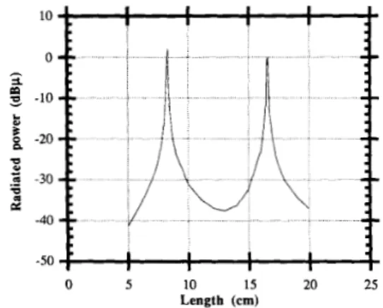
The spurious power, as defined by Equation (14), is calculated for a microstrip line terminated by matched loads, open circuits and short circuits at both terminals and, a matched load on the left and a complex load of 8 pF//20 KQ on the right terminal. The results are given in Figs. 6 , 7, 8, and 9, respectively. The radiation from a microstrip line terminated by a pair of matched loads is very small (see Fig. 6) as compared to those terminated by other loads. The highest radiation occurs for the open- circuited and the short-circuited transmission lines of res- onant lengths. The radiated power has a sharp peak around the resonance length of the line, and it becomes essen- tially negligible for off-resonance lengths. For the com- bination of matched and complex load terminations, Fig. 9, the total radiated power is slightly larger than that of matched load termination case shown in Fig. 6 .
2069
AKSUN AND MITTRA: ESTIMATION OF SPURIOUS RADIATION FROM MICROSTRIP ETCHES
0 5 10 15 20 25 Length (em)
Fig. 7 . Radiated power as a function of the length of the line for open- circuit termination at both ends.
10 0
*
-10 -20 -30 .9 -40 a-
b-
E
s
z
-50 -60 I I I I I I I! : ~
I I It
0 5 10 15 20 25 Length (cm)Fig. 8. Radiated power as a function of the length of the line for short- circuit termination at both ends.
-36 -37 2 -38
-
-39-
B
g
-40 0 ) n4
-413
-42 -43 -44 0 .- 0 5 10 15 20 25 Length (cm)Fig. 9. Radiated power as a function of the length of the line for a matched load and a complex load Z, = (20 K//8 pF) terminations.
IV. CONCLUSIONS
The current distribution on a microstrip line, which is fed by a current source at an arbitrary location and ter- minated by complex loads at both ends, has been com- puted by using the closed-form representations of the spa- tial domain Green’s functions.
It has been found that the use of closed-form spatial domain Green’s functions in the context of the method of
moments formulation reduces the computation time sig- nificantly as compared to the conventional formulation in the spectral domain. For instance, in a numerical experi- ment with 40 roof-top basis functions, the computation time for the current distribution is on the order of 50-60
CPU sec on the DECstation 5000/200 system when the closed-form Green’s functions in the format given in [41 are used, whereas it takes on the order of 10 CPU mins. on Cray/YMP for the same calculation using the spectral domain approach. The method described is quite general and is useful for arbitrary geometrical disposition of the microstrip etches, e.g., arbitrary bends, and not just straight sections.
The investigation of the radiation leakage from a mi- crostrip line terminated by complex loads has shown that the highest radiation occurs when the length of the line is near resonance, and the terminations are either open or short circuits. It is also observed that a matched load ter- mination at one of the terminals of the microstrip inter- connect reduces the radiation leakage significantly, as compared to the radiation levels for other terminations that can cause resonances to occur.
ACKNOWLEDGMENT
This work was supported in part by the Joint Services Electronics Program under Grant NO00 14-90-5- 1270. Support from the National Center for Supercomputing Applications at the University of Illinois for computer time on the Cray/YMP supercomputer is also acknowl- edged.
REFERENCES
[ l ] R. F . Harrington, Field Computafion by Moment Method. New York, MacMillan, 1968.
[ 2 ] Y . L. Chow, J . J . Yang, D. H. Fang and G . E . Howard, “Closed-
form spatial Green’s function for the thick substrate.” IEEE Trans.
Microwave T h e o q Tech., vol. 39, pp. 588-592, Mar. 1991.
[3] Y. L. Chow and J . J . Yang, “Modeling of electromagnetic fields in layered media by the simulated image technique,” Directions in Elec-
tromagnetic Wave Modeling, H . L. Bertoni, and L. B. Felsen, Eds., New York: Plenum, 1991.
[4] M. 1. Aksun and R. Mittra, “Deviation of closed-form Green’s func-
tions for a general microstrip geometry,” accepted for publication in
IEEE Trans. Microwave Theory Tech.
[ 5 ] -, “Choices of basis and testing functions for the method of mo- ments in electromagnetic problems.” submitted for publication. [6] R . A. York, R. C . Compton, and B. J . Rubin,” Experimental veri-
fication of the 2-D rooftop approach for modeling microstrip path an- tennas,” IEEE Trans. Antennas Propagat., vol. 39, pp. 690-694, May 1991.
171 J . T . Aberle and D . M. Pozar, “Analysis of infinite arrays of probe- fed rectangular microstrip patches using a rigorous feed model,” Proc.
Inst. Elec. Eng.. vol. 136, pp. 110-1 19, Apr. 1989.
[8] H. Sobol, “Application of integrated circuit technology to microwave frequencies,” Proc. IEEE, vol. 59, pp. 1200-121 I , Aug. 1971.
191 C. T . Tai, Dyadic Green’s Functions in Electromagnetic Theory. San Francisco: Intemational Textbook 1971.
[ l o ] T. Itoh, “Spectral domain immittance approach for dispersion char- acteristics of generalized printed transmission lines,” IEEE Trans.
Microwave Theory Tech., vol. MTT-28, pp. 733-736, July 1980.
M. Irsadi Aksun, for a photograph and biography, see this issue, p. 2062.
Raj Mittra (S’54-M’57-SM’69-F’7 l ) , for a photograph and biography, see this issue, p . 2062.