L .W .E ! ! û 9 t Ü ^ t R 2 \ Ù ü 9ήΧΐ!
ur:-\ Γ^‘'5í^
T -/C 7 S ^ 2
LASER WAVELENGTH UPCONVERSION
WITH
OPTICAL PARAMETRIC OSCILLATORS
USING
SIMULTANEOUSLY PHASE-MATCHED CRYSTALS
A DISSERTATION
SUBMITTED TO THE DEPARTMENT OF ELECTRICAL AND ELECTRONICS
ENGINEERING
AND THE INSTITUTE OF ENGINEERING AND SCIENCES
OF BILKENT UNIVERSITY
IN PARTIAL FULFILLMENT OF THE REQUIREMENTS
FOR THE DEGREE OF DOCTOR OF PHILOSOPHY
By
Tolga Kartaloglu
September 2002
В069064
Т КI certify th at I have read this thesis and that in my opinion it is fully adequate, in scope and in quality, as a thesis for the degree of Doctor of Philosophy.
Assoc. Prof. Dr. Orhan Aytiir (Supervisor)
I certify that I have read this thesis and th at in my opinion it is fully adequate, in scope and in quality, as a thesis for the degree of Doctor of Philosophy.
Prof. Dr. Abdullah Atalar
I certify th at I have read this thesis and th at in my opinion it is fully adequate, in scope and in quality, as a thesis for the degree of Doctor of Philosophy.
İÎ/.:i
i\
I certify that I have read this thesis and that in my opinion it is fully adequate, in scope and in quality, as a thesis for the degree of Doctor of Philosophy.
I certify that I have read this thesis and that in my opinion it is fully adequate, in scope and in quality, as a thesis for the degree of Doctor of Philosophy.
Approved for the Institute of Engineering and Sciences:
Prof. Dr. Mehmet
ABSTRACT
LASER WAVELENGTH UPCONVERSION W ITH OPTICAL
PARAMETRIC OSCILLATORS USING SIMULTANEOUSLY
PHASE-MATCHED CRYSTALS
Tolga Kartaloglu
Ph.D. in Department of Electrical and Electronics Engineering
Supervisor: Assoc. Prof. Dr. Orhan Aytiir
September 2002
In this thesis, we present our work on optical parametric oscillators that employ a single nonlinear crystal that is simultaneously-phase-matched for second-harmonic or sum-frequency generation in order to obtain frequency upconversion of laser radiation. We achieved simultaneous phase matching of optical parametric amplification together with second harmonic generation or sum frequency generation in bulk KT10P 04 and KTi0 As04 crystals, and in an aperiodically-poled LiNbOs crystal. We demonstrated very efficient frequency conversion of pulsed and continuous-wave lasers to higher frequencies with power conversion efficiencies reaching 40%. In addition, we present our work on an intracavity-doubled optical parametric oscillator that employs a periodically- poled K T10P 04 crystal for optical parametric amplification and an intracavity (3- Ba2B04 crystal for second harmonic generation. In this thesis, we also introduce a method for designing aperiodic grating structures for simultaneous phase matching in poled nonlinear crystals. In contrast to periodic grating structures, a grating structure designed using our method allows one to achieve simultaneous quasi-phase matching of two arbitrarily chosen nonlinear interactions with freely adjustable coupling coefficients.
K eyw ords; nonlinear frequency conversion, optical parametric oscillators, para metric devices, second harmonic generation, sum frequency generation, quasi-phase matching, aperiodically-poled.
ÖZET
AYNI ANDA FAZ UYUMU SAĞLANMIŞ KRİSTALLER
KULLANARAK OPTİK PARAMETRİK OSİLATÖRLER İLE
LAZER DALGABOYU YUKARI-ÇEVRİMİ
Tolga Kartaloğlu
Elektrik ve Elektronik Mühendisliği Doktora
Tez Yöneticisi: Doç. Dr. Orhan Aytür
Eylül 2002
Bu tezde, lazer ışımasının frekans yukarı çevrimi elde etmek amacı ile ikinci harmonik veya toplam frekans üretimi için aynı anda faz uyumu sağlanmış tek bir doğrusal olmayan kristal kullanan optik parametrik osilatörler üzerine çalışmalarımızı sunmaktayız. Kütle halinde KTİOPO4 ve KTİOASO4 kristallerinde ve periyodik olmayacak şekilde kutuplanmış LiNbOs kristalinde, ikinci harmonik üretimi veya toplam frekans üretimi ile birlikte optik parametrik yükseltmenin aynı anda faz uyumunu sağlamayı başardık. Deneysel olarak %40’a varan güç dönüşüm verimi ile, yüksek frekanslara darbeli ve sürekli-dalga lazerlerin çok verimli frekans dönüşümünü gösterdik. Bunlara ek olarak, ikinci harmonik üretimi için kovuk içi ^ -B a2BÛ4 kristali ve optik parametrik osilasyon için periyodik şekilde kutuplanmış KTİOPO4 kristali kullanan kovuk-içi-katlanrnış optik parametrik osilatörürnüzü de sunmaktayız. Bu tezde, ayrıca, kutuplanmiş doğrusal olmayan kristalerde aynı anda faz uyumu sağlanmak için periyodik olmayan parmaklık yapısı tasarlamak için bir yöntemi tanıtmaktayız. Periyodik parmaklık yapıların aksine, bizim yöntemimiz ile tasarlanmış parmaklık yapıları serbestçe ayarlanabilen birleştirme katsayıları ile keyfi seçilmiş iki doğrusal olmayan etkileşimin aynı anda görünüşte faz uyumunu başarmaya izin vermektedir.
A n a h ta r K elim eler: doğrusal olmayan frekans dönüştürme, optik parametrik osilatörler, parametrik cihazlar, ikinci harmonik üretimi, toplam frekans üretimi, görünüşte faz uyumu sağlama, periodik olmayan kutuplama.
ACKNOWLEDGMENTS
I would like to thank Assoc. Prof. Dr. Orhan Aytiir for his supervision, special guidance, suggestions, and encouragement through the development of this thesis.
Special thanks to Prof. Dr. Abdullah Atalar, Prof. Dr. Hayrettin Köymen, Prof. Dr. Ekmel Ozbay, and Assoc. Prof. Dr. Feza Arikan for reading and commenting on the thesis.
During this long journey. Kahraman Güçlü Köprülü has been a close friend. We shared most problems since our undergraduate days. I am grateful to Hakkı Tunç Bostancı, Uğur Oğuz, Ayşegül Şahin, Murat Akgül, Lütfiye Durak, Ayhan Bozkurt, Ercan Solak ( “tertip”). Ziya Gürkan Figen, and Vakur Ertürk for making my life at Bilkent University more pleasant with their friendship.
I would like to express my thanks to our department secretary Mürüvet Parlakay and laboratory technicians Ergün Hırlakoğlu and Ersin Başar for their help during my presence at the department of Electrical Engineering.
It is a pleasure to express my special thanks to my mother, father, and brother for their sincere love, support, and encouragement.
I would also like to express my thanks to the Turkish Scientific and Technical Research Council for their partial support of this work under Grand No. EEEAG-118 and Grand No. 197E050.
C ontents
1 Introduction 1
2 Optical Parametric Interactions 11
2.1 Nonlinear M aterials... 11
2.2 Second-order Nonlinear Polarization... 13
2.3 Coupled-Mode E q u atio n s... 14
2.4 Parametric In teractio n s... 17
2.4.1 Sum-frequency Generation and Phase M a tc h in g ... 19
2.4.2 Difference-frequency Generation 21 2.4.3 Second Harmonic Generation 22 2.4.4 Optical Parametric O scillation... 23
2.5 Simultaneously Phase-matched Interactions... 26
3 Phase Matching 30 3.1 Biréfringent Phase M atch in g ... 30
3.2 Quasi-Phase M a tc h in g ... 32
3.3 Calculation of Phase Matching Curves 35 3.4 Simultaneous Phase M a tc h in g ... 39
3.4.1 Simultaneous Phase Matching with B P M ... 39
3.4.2 Simultaneous Phase Matching with Periodic Q P M ... 40
3.4.3 Simultaneous Phase Matching with Aperiodic Q P M ... 41
3.5 Aperiodic Grating Design M e th o d ... 43
4 Overview of Experimental Work 47 4.1 Optical Parametric O scillators... 47
4.1.1 Continuous-wave Optical Parametric O scillato rs... 48
4.1.2 Femtosecond Optical Parametric O s c illa to rs... 50
4.1.3 SHG and SFG with Optical Parametric O s c illa tio n ... 51
4.2 Simultaneous Phase M a tc h in g ... 52
4.2.1 Simultaneous Phase Matching with КТЮ РО4 ... 52
4.2.2 Simultaneous Phase Matching with KTi0 As04 54 4.2.3 Periodically-Poled КТЮ РО4 C r y s t a l ... 56
4.2.4 ;0-B a2BO4 C r y s t a l ... 56
4.2.5 Aperiodically-Poled LiNbOs Crystal Design 57 4.3 Experimental D evices... 60
4.3.1 Continuous-wave Argon-ion L a s e r ... 60
4.3.2 Femtosecond Laser S o u r c e ... 60
4.3.3 Laser O p tic s... 60
4.4 Measurement Techniques and Instruments 61 5 Femtosecond Experiments 63 5.1 Self-doubling KTP O P O ... 63
5.2 Self-doubling KTA Ο Ρ Ο ... 69 5.3 Sum-frequency-generating KTP O P O ... 74
5.4 PP-K TP OPO and SHG with BBO Crystal 82
5.5 Self-doubling APLN O P O s ... 87
6 Continuous-wave Experiments 91
6.1 Continuous-wave Ti:sapphire L a s e r ... 92
6.2 Continuous-wave Self-doubling KTA OPO 92
6.3 Continuous-wave Self-doubling APLN O P O s ... 97
7 Conclusion 103
Appendix 107
A Miller’s Rule Factor 107
List of Figures
2.1 Change in photon flux densities for = 0,1,10 and 50... 19
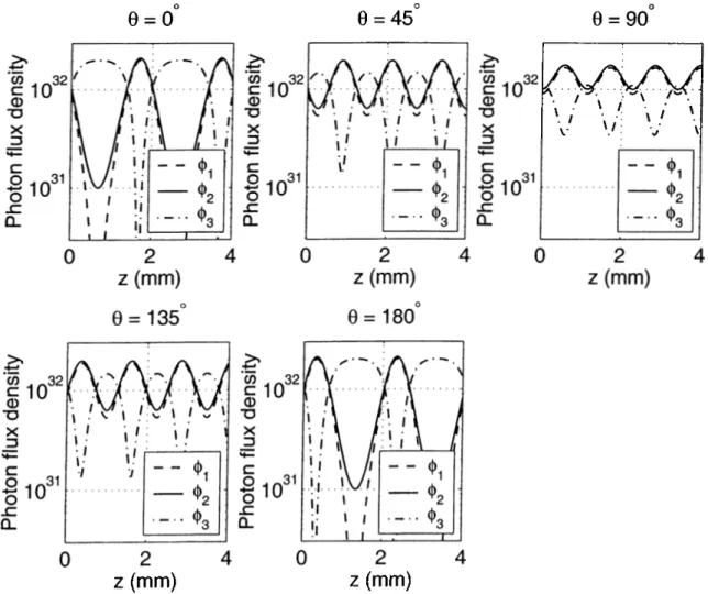
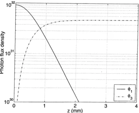
2.2 Change in photon flux densities for various phase angles. 21 2.3 Change in photon flux densities for SHG... 23
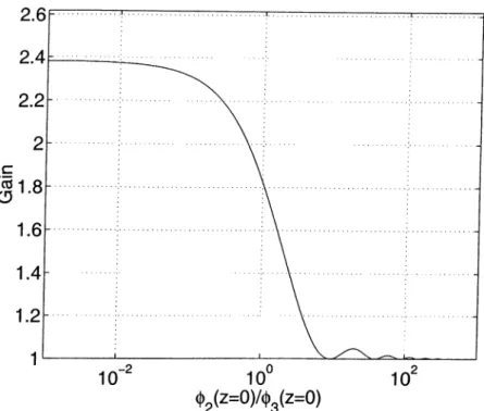
2.4 Gain saturation with the increase in the signal input... 24
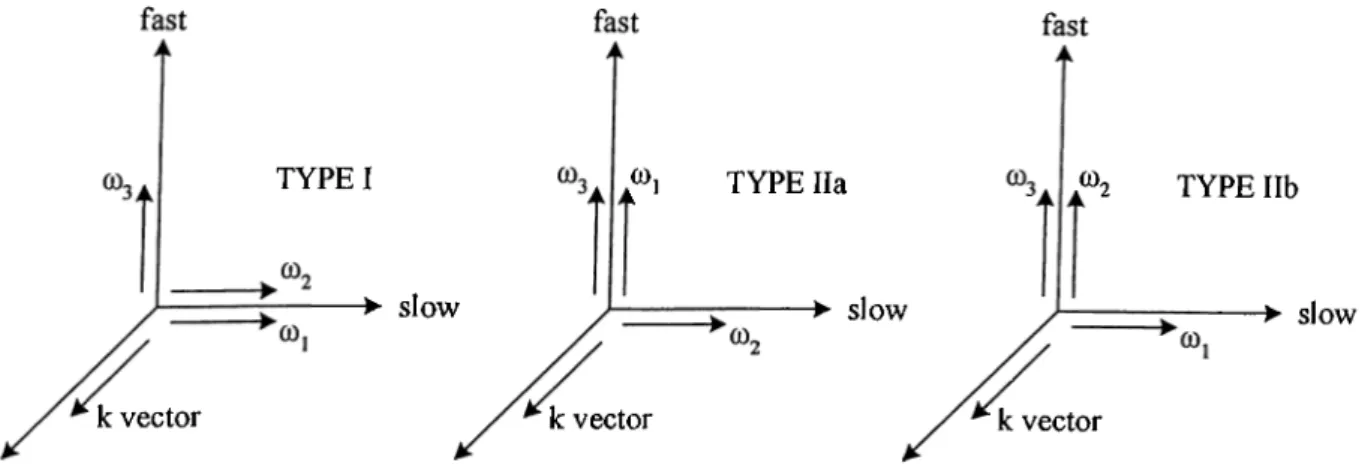
3.1 Directions of polarizations for type-I and type-II phase matching. 31 3.2 A phase-matched parametric amplification... 34
3.3 The direction of the first wavevector... 36
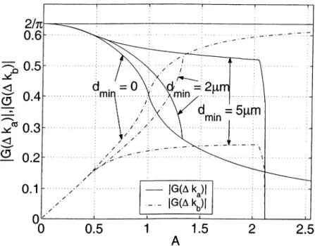
3.4 |G(A^a)| and 1G(AA:6)| for dmin = 0) 2^m, and 5^m ... 45
3.5 |G(AA:a)|^ + \G{Akb)\'^ for d^m = 0, 2/xm, and 5/xm... 45
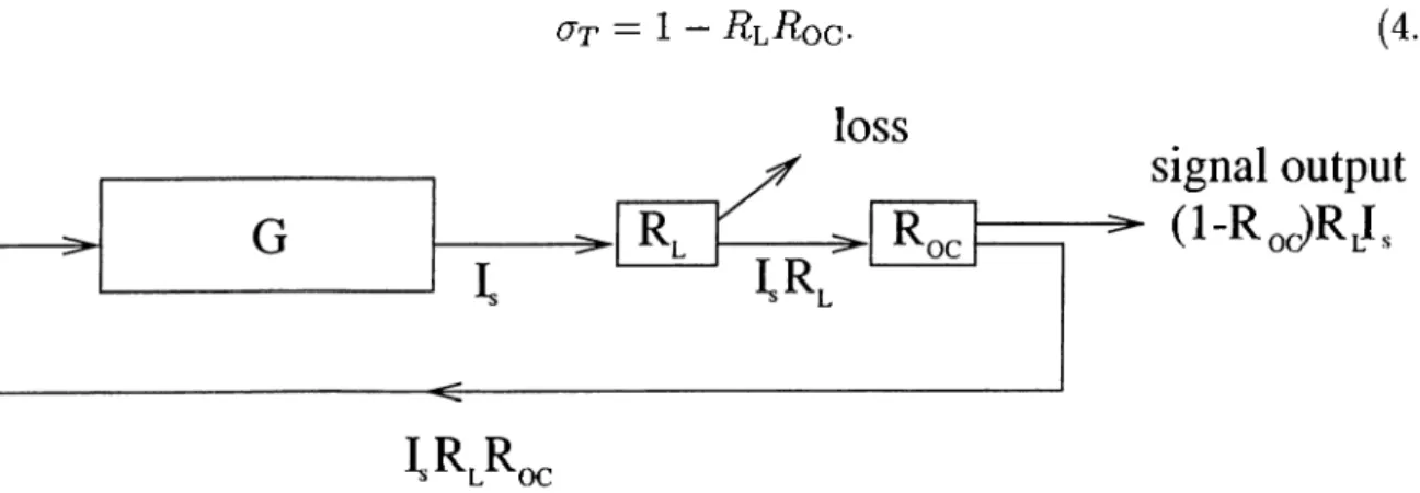
4.1 Schematic of an OPO. 47 4.2 A model of an OPO... 48
4.3 Synchronous pumping... 50
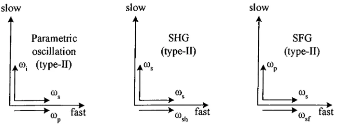
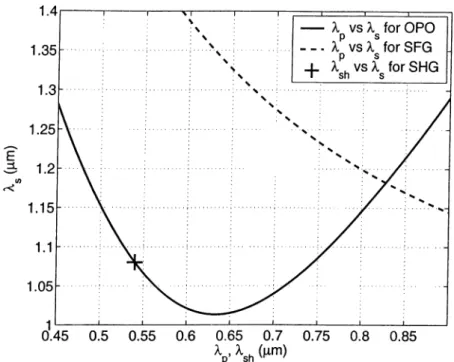
4.4 Phase matching configurations for SHG and SFG... 52
4.5 The phase matching curves for KTP. 53 4.6 Phase matching configurations for SHG. 54 4.7 The phase matching curves for KTA... 55
4.8 Lengths of domains as functions of domain number... 57 4.9 Expanded diagram illustrating a segment of the first grating... 58 4.10 Magnitude of the normalized Fourier transform |^(ΔΑ:)| for the gratings. 58 4.11 Mirror power calibration... 61
5.1 Self-doubling OPO setup. 64
5.2 Self-doubling OPO output power at 540 nm as a function of a polarization rotation angle... 65 5.3 Self-doubling OPO output power at 540 nm as a function of input pump
power... 66 5.4 Spectrum of the self-doubling OPO output at 540 nm. 67 5.5 Calculated tuning curves for the self-doubling O PO ... 67 5.6 Experimental setup of the SD-OPO... 69 5.7 SD-OPO output power at 575 nm as a function of polarization rotation. . 71 5.8 SD-OPO output power at 575 nm as a function of input pump power. . . 72 5.9 Spectrum of the SD-OPO output... 72 5.10 Autocorrelation traces of the SD-OPO output... 73 5.11 The experimental setup for the SF-OPO... 74 5.12 Power conversion efficiency as a function of polarization rotation. 76 5.13 The pump depletion and the intracavity signal power... 77 5.14 Optimum polarization rotation angle and maximum power conversion
efficiency as functions of pump power... 78 5.15 Power conversion efficiencies as functions of the group delay... 79 5.16 Calculated tuning curves for the SF-OPO... 80
5.17 Autocorrelation trace and spectrum of the sum-frequency output beam. . 81
5.18 The intracavity-doubled OPO setup. 83 5.19 Conversion efficiency and pump depletion versus pump power... 84
5.20 Measured second-harmonic output wavelength and power versus cavity length detuning... 85
5.21 Femtosecond self-doubling OPO setup... 87
5.22 Signal and second-harmonic spectra for the second grating {β — 0.72). . . 88
5.23 Power conversion efficiency as a function of the pump power... 88
6.1 Tirsapphire laser setup... 91
6.2 Continuous-wave SD-OPO setup... 93
6.3 Pump spectrum with and without optical parametric oscillation... 95
6.4 Signal spectrum with and without SHG... 95
6.5 Second-harmonic spectrum. 96 6.6 Continuous-wave SD-OPO setup... 97
6.7 The intracavity Ti:sapphire laser powers for β = 0.39, 0.50, 0.61 and 0.72. 98 6.8 The intracavity signal power Pg for β — 0.39, 0.50, 0.61 and 0.72. 99 6.9 The second-harmonic output powers for β = 0.39, 0.50, 0.61 and 0.72. . . 99
6.10 Pump wavelength tuning... 100
6.11 Temperature tuning...100
List o f A bbreviations
APLN aperiodically-poled lithium niobate (LiNbOs) BBO beta-barium borate (/?-Ba2B04)
BPM biréfringent phase matching cw continuous-wave
DBS dichroic beamsplitter
DFG difference-frequency generation GVD group velocity dispersion
GVM group velocity mismatch HWP half-wave plate
KTA potassium titanyl arsenate (KTi0 As04) KTP potassium titanyl phosphate (KTi0 P 04) OC output-coupler
OPO optical parametric oscillator
PP-K TP periodically-poled potassium titanyl phosphate QPM quasi-phase matching
QWP quarter-wave plate
SD-OPO self-doubling optical parametric oscillator
SF-OPO sum-frequency generating optical parametric oscillator SFG sum-frequency generation
SHG second harmonic generation THG third harmonic generation Tiisapphire titanium rsapphire
Chapter 1
Introduction
Ever since the invention of the laser by Maiman [1] in 1960, there has been a great deal of interest in the development of coherent light sources at new frequencies, since laser sources have broad applications in both research and industry. In addition, continuous frequency tunability is a benefit because there are various applications that need a range of frequencies to be spanned. Unfortunately, lasers cannot generate every desired frequency. Therefore, to obtain a new coherent source, frequency conversion of an available laser source to another frequency is important and if possible, tunability of this new source is an advantage.
In general, the response of optical materials to light is not linear. High intensity optical beams provided by lasers enable us to observe this nonlinearity. The field of nonlinear optics investigates this kind of interaction of light with materials. Optical materials that show high nonlinear response are called nonlinear materials.
By means of nonlinear optical processes, frequency conversion of lasers is possible. Second harmonic generation (SHG), sum frequency generation (SFG), optical parametric generation, and optical parametric amplification are widely used processes of nonlinear optics caused by second-order nonlinearity in a material. Using SHG or SFG, the frequency of laser light can be converted to a higher frequency (upconversion). On the contrary, an optical parametric oscillator (OPO) based on an optical parametric amplifier provides tunable conversion to lower frequencies (downconversion). Tunable
upconversion is possible by using two nonlinear processes one after another, i.e., upconversion followed by tunable downconversion or vice versa. We discovered that it is possible to achieve these two processes simultaneously within the same nonlinear material for efficient conversion [2]. As a result, we investigated simultaneous processes for upconversion and performed various experiments on OPOs employing these processes [3]-[10]. In this thesis, we present our work on these OPOs.
The field of nonlinear optics began in 1961 with the first example of frequency conversion. This was frequency doubling of a ruby laser using a quartz crystal by Franken [11]. Due to the nonlinear response of the crystal, a light beam at twice the frequency (second harmonic) of the laser beam was generated. The system was not tunable and the efficiency was less than one part per billion because a condition known as the phase matching condition was not satisfied in this experiment.
In addition to a nonlinear response, an efficient nonlinear interaction requires a means of achieving the phase matching condition. This condition states that phases of the interacting waves must be matched over an interaction distance of many optical wavelengths. Therefore, this condition is a requirement of momentum conservation. The early research on nonlinear optics led to an understanding of methods to achieve this condition. Two methods that are widely employed today are the use of birefringence to offset dispersion [12], [13] and the use of a periodic modulation of the sign of the nonlinear coefficient to periodically reset the optical phase [14]. The former method is referred to as biréfringent phase matching (BPM) and the later method is now referred to as quasi-phase matching (QPM).
In 1962, Armstrong et al. [14], Kingston [15], and Kroll [16] proposed and analyzed the idea of tunable light generation by parametric amplification and parametric generation. Three years later in 1965, Wang and Rachetti [17] achieved the first experimental demonstration of parametric gain using a material that shows second-order nonlinearity. In the same year, Giordmaine and Miller [18] achieved the first parametric oscillation. They used a Q-switched Nd:CaW04 laser frequency-doubled to the green in LiNbOa, to pump a monolithic LiNbOa tunable parametric oscillator.
Miller, a material showing second-order nonlinearity was used to interact three optical waves whose frequencies are related by uz = u>i + u>2 [14]-[16]. SFG, SHG, difference
frequency generation (DFG), and optical parametric amplification and generation are different types of second-order nonlinear interactions of three optical waves, and are collectively referred to as three-wave mixing processes. They are also called three photon optical parametric processes. For example, in the SFG process, the nonlinearity in the material causes two photons at different frequencies to be combined to produce a single photon whose frequency is the sum of the frequencies of the initial two photons. As a result, three photons at different frequencies are involved in a SFG process. A SHG process is a special case of SFG in which the frequencies of the initial two photons are same.
Optical parametric amplification and DFG are the same processes. In the optical parametric amplification process, initially there are two photons. One of them is at a higher frequency than the other and is called a pump photon. The other one is at a lower frequency and is called a signal photon. In the process, the pump photon splits into two photons at lower frequencies with the influence of the signal photon. As a result, a new photon whose frequency is the difference of the frequencies of the pump and the signal photons, called an idler photon, and a photon identical to the signal photon are created. As a result, in addition to the generation of an idler photon at the difference frequency, the number of signal photons is increased.
Generation of new photons with optical parametric amplification does not necessarily require an initial signal photon. Spontaneous parametric generation of two photons from a pump photon is also possible. In the spontaneous parametric generation process, the pump photon at frequency Up breaks down into a signal and an idler photon at lower frequencies lOs and respectively. Energy and momentum are conserved in the process.
These correspond to the relation of the frequencies, ujp — tOs + u>i, and the matching of the wavevectors, kp = k* -h kj, of the waves corresponding to the pump, the signal and the idler photons. The wavevector matching, i.e. conservation of momentum, formulates the phase matching condition.
frequency. On the other hand, optical parametric generation can achieve tunable conversion to a band of frequencies. For this purpose, an OPO can be constructed by simply adding optical feedback around a parametric generator-amplifier, just like in a laser. However, in contrast to most lasers, OPOs are truly tunable sources of coherent radiation because they employ optical parametric generation where tunable virtual energy levels are involved in the process.
An OPO is analogous to an optically pumped three-level laser. The frequency of the pump beam determines the top energy level. The mid-energy level is determined by the frequency of the signal and the idler beams that satisfy the phase matching condition. These energy levels are virtual and non-resonant in contrast to lasers. Continuous tuning of the OPO is achieved by externally changing the phase matching condition. Since the phase matching condition depends on the refractive indices and the frequencies of the light beams, the frequencies can be changed by adjusting the refractive indices. To do this, one can change the temperature of the material (temperature tuning) or change the propagation direction of the light beams (angle tuning).
Most of the characteristics of OPOs are determined by their pump sources. An OPO pumped by a continuous-wave (cw) laser generates a continuous-wave output. Its resonator size can be as small as the length of the nonlinear gain medium. However, Q-switched lasers provide pulsed outputs. Pulse widths are on the order of 10 ns with low repetition rates. Although the duration of the pulses are short, their peak powers are so high th at there are many efficient OPOs designed to operate with Q-switched lasers [19]. In these OPOs, each laser pulse starts a new oscillation, generating a new output pulse because the OPO cavity length is much smaller than the pump pulse length, and a signal pulse resonating inside the cavity can build up by multiple passes within a single pump pulse.
Mode-locked lasers also provide pulsed outputs. These sources produce short pulses with high repetition rates. Pulse widths are on the order of lOOfs-lOOps. Although they have high peak powers like Q-switched lasers, a single pulse from a mode-locked laser is not enough to produce an oscillation in an OPO, because the duration of these pulses are not long enough for oscillations to build up. Therefore, a method called “synchronous
pumping” is employed in OPOs pumped by mode-locked lasers. In this method, the cavity length of the OPO is adjusted for a synchronous operation with a mode-locked pump laser, pump pulses always meet and propagate with the intracavity signal pulse in the nonlinear material, while the intracavity signal pulse travels back and forth in the OPO cavity. As a result, each pump pulse gives some energy to the signal pulse. As the signal pulse grows, it saturates the gain of the parametric amplifier and reaches a steady level where energy taken from the pump pulse just compensates for the losses of the signal pulse in the cavity. From this point of view, its operation characteristic is similar to a cw OPO operating in a steady-state condition.
Since 1965, there have been many demonstrations of OPOs with different kinds of lasers as pump sources. A special issue of the Journal of the Optical Society of America Part B in published 1993 [19] covered the achievements made in the field of parametric devices during the previous two decades. Articles on cw parametric devices, pulsed high peak power infrared tunable sources, visible parametric sources, synchronously-pumped picosecond and femtosecond parametric devices, and spectroscopic applications can be found in this issue. A second special issue on parametric devices was also published in 1995 [20]. In this issue, highly efficient devices, frequency control and spectroscopic applications, picosecond and femtosecond synchronously-pumped parametric devices, and parametric amplifiers were covered. An important article in this issue was about the first demonstrations of the quasi-phase-matched OPOs in bulk periodically-poled LiNbOs by Myers et al. [21].
Although QPM was proposed in 1962 together with the idea of BPM, and the first OPO using BPM was demonstrated in 1965, the demonstration of an OPO using QPM has taken much longer. This is due to the fact that until 1994 crystal quality and technology did not allow the control of ferroelectric domains with the required precision in bulk crystals [22]-[24]. The electric field induced domain inversion process, discovered by Yamada et al. [25], results in a crystal structure in which the sign of the nonlinear coefficient is modulated. This process led to a success for bulk crystals in 1994 and quasi-phase-matched second harmonic generation was demonstrated by Burns et al. [26] and Webjorn et al. [27] in the same year.
The field of nonlinear optics also depends on the progress in the laser sources, as well as the improvement of nonlinear optical materials. For example, Rhodamine 6G dye laser is the first laser that pumped a femtosecond OPO [28]. After this, there have been many demonstrations of femtosecond OPOs [29]-[33], especially using titaniumrsapphire (Ti:sapphire) lasers.
Until we have demonstrated efficient frequency upconversion using an optical parametric oscillator pumped by a femtosecond Ti:sapphire laser that employ a single nonlinear crystal which is also phase-matched for second-harmonic generation (SHG) in 1997 [4], tunable frequency conversion of a mode-locked laser to higher frequencies was achieved using two nonlinear crystals; one for parametric oscillation with tunable conversion and one for SHG or SFG for upconversion. In one approach, the OPO is pumped by the frequency-doubled pump laser output [34]. A more widely used approach is to frequency-double the signal (or the idler) beam outside [35] or inside [36], [37] the OPO cavity. For this approach, intracavity operation is usually preferred in order to take advantage of the high intensity of the resonant field. Another approach is SFG with the residual (unconverted in the OPO) pump and the signal or idler. This can also be implemented extracavity or intracavity [38],[39]. These upconversion OPOs have successfully generated tunable ultrafast pulses at visible wavelengths, however mostly with limited conversion efficiencies (~ 10%), with the exception of [38] (25% with SFG, 31% with SHG).
The simultaneous phase matching of two different second-order nonlinear processes within the same crystal opens up many frequency conversion possibilities [40]. Since 1997, we have employed simultaneous phase matching in our OPOs to obtain upconversion [5]-[10]. In addition, there has been a growing interest in the simultaneous phase matching of two different nonlinear interactions within the same second-order nonlinear crystal in recent years [3]-[10], [41]-[68], because simultaneous phase matching allows efficient frequency conversion of two-step interactions. For example, the combination of optical parametric oscillation with SHG in the same second-order nonlinear crystal in one of our experiments results in very efficient frequency conversion reaching 34% [4].
There have been various experimental demonstrations of simultaneously-phase- matched interactions using either BPM [3]-[10], [40], [41] or periodic QPM [44], [46]-[51]. However, simultaneous phase matching occurs by chance for both BPM and periodic QPM i.e., given a pair of source and target frequencies, there is no guarantee that either method will come up with a suitable crystal design.
In simultaneous phase matching, the relative strength of the two processes is also important because this affect the over all conversion efficiency [42], [43]. Unfortunately, neither BPM nor periodic QPM methods allow any room for adjusting this important parameter.
In order to overcome the restrictions of BPM and periodic QPM, a number of groups have recently proposed the use of quasi-periodic or aperiodic poling schemes to achieve simultaneous phase matching with QPM [8],[9],[52]-[68]. In one of these schemes, quasi- periodic grating structure based on Fibonacci sequences is used [52]-[61]. Third harmonic generation (THG) [53], [56], [58], [61] and multiple-peak frequency doubling [54], [55] (phase-matched SHG for a number of distinct discrete frequencies) were experimentally demonstrated using such schemes. However, Fibonacci-based schemes also suffer from the limitation of BPM and QPM and cannot be used to achieve simultaneous phase matching. This limitation was alleviated by an extension of Fibonacci-based schemes that allow independent phase matching of the two interactions [62]-[64]. Two-peak frequency doubling [63] and THG [63], [64] were experimentally demonstrated using these structures. However, neither approach of Fibonacci sequences provides a general mechanism to adjust the relative strength of the two simultaneously phase-matched processes. Aperiodic schemes are solutions to both limitations of BPM and periodic QPM. In one method, aperiodic schemes that are optimized using simulated annealing for maximizing the conversion efficiency were proposed for multiple-peak frequency doubling, tripling, and parametric amplification [65]-[67]. However, this approach does not take pump depletion into account, and cannot be expected to yield accurate results. Another scheme for designing aperiodic grating structures which enables free adjustment of the relative strength of the two processes was proposed [68], but awaits experimental verification. Recently, we have also proposed a method employing aperiodic schemes for QPM and demonstrated the idea with experiments [8], [9].
In this thesis, we present our work on OPOs that employ a single simultaneously phase-matched nonlinear crystal for tunable frequency upconversion of laser radiation. We achieved simultaneous phase matching of optical parametric oscillation together with SHG or SFG in bulk KTi0 P 04 (KTP) and KTi0 As04 (KTA) crystals and an aperiodically-poled LiNbOa crystal (APLN). We demonstrated efficient frequency conversion of pulsed and cw lasers to higher frequencies. In addition, we present our work on an intracavity-doubled OPO that employs a periodically-poled KTP (PP-KTP) crystal for optical parametric amplification and an intracayity ^ -B a 2B04 (BBO) crystal for SHG. In this thesis, we also introduce a method for designing an aperiodic grating structure for poling of nonlinear crystals.
We designed and implemented two phase-matched self-doubling optical parametric oscillators (SD-OPOs) where a single nonlinear crystal is employed for both parametric generation and frequency doubling using BPM. One of our SD-OPO is based on a KTP crystal th at is synchronously-pumped by a femtosecond Tirsapphire laser operating at a wavelength of 745 nm [3],[4]. When pumped at this wavelength, the KTP crystal is phase- matched for parametric generation at a signal wavelength of 1080 nm, corresponding to an idler wavelength of 2400 nm. The singly-resonant OPO cavity consists of highly reflecting mirrors at the signal wavelength. The signal beam is also phase-matched for SHG at the same crystal orientation. W ith proper intracavity polarization rotation, a frequency-doubled output beam at a wavelength of 540 nm is generated. A power conversion efficiency of 34% is achieved in the KTP crystal. To our knowledge, this is the first demonstration of phase-matched optical parametric oscillation and frequency doubling within a single crystal.
Other SD-OPO is based on KTA crystal [10]. The SD-OPO is also synchronously- pumped by the Ti:sapphire laser operating at a wavelength of 796 nm. BPM in the KTA crystal leads to a signal beam at 1150 nm. Simultaneously phase-matched frequency doubling of the intracavity signal beam within the same KTA crystal is also facilitated by intracavity rotation of the signal polarization. The resulting yellow beam at 575 nm exits the cavity via a dichroic beam-splitter. A fixed time delay introduced between the two orthogonally polarized intracavity signal pulses is shown to alleviate temporal pulse overlap problems associated with group velocity mismatch (GVM). The overall
(796 nm to 575 nm) power conversion efficiency of the two step process is 39.4% in KTA crystal. To our knowledge, this is the highest value reported to date for an intracavity frequency-doubled OPO.
We also designed and implemented a synchronously-pumped single-crystal sum- frequency generating OPO (SF-OPO) where the SFG process takes place within the OPO crystal itself [5]-[7]. Our SF-OPO is based on a KTP crystal where BPM is used for both processes. The polarization geometry of the two phase matching conditions necessitates a pump polarization that is at an angle to the fast and slow axes of the biréfringent KTP crystal. Adjusting the group delay between the fast and slow components of the pump to compensate for the GVM in the KTP crystal increases the photon conversion efficiency by more than three fold. We have demonstrated 43% power conversion efficiency from the pump to the sum-frequency beam.
In addition to these simultaneously-phase-matched OPOs, we implemented an intracavity-doubled OPO that employs a periodically-poled KTP (PP-KTP) crystal for optical parametric amplification and a BBO crystal for SHG. Our OPO is synchronously- pumped by a Ti:sapphire laser operating at a wavelength of 760 nm. Quasi-phase matching is achieved with a 24 μνα. poling period in the PP-K TP crystal, resulting in a signal wavelength of 1260 nm and an idler wavelength of 1915 nm. Type-I SHG of the signal beam is achieved in the BBO crystal. The SHG output is tunable over a 90 nm range around 630 nm by changing the cavity length [69]. We achieved maximum conversion efficiency of 15.9%.
In this thesis, we describe a method for designing an aperiodic grating structure to simultaneously phase match two arbitrary second-order nonlinear processes within the same crystal. This method also allows the relative strength of the two processes to be adjusted freely. We performed an experiment based on an aperiodically- poled LiNbOs (APLN) crystal designed using our method [8], [9]. In this crystal, parametric oscillation and SHG are simultaneously phase-matched for upconversion of a femtosecond Ti:sapphire laser to 570 nm. This self-doubling OPO (SD-OPO) provides an experimental verification of our design method.
used in the femtosecond experiments. In these OPOs, we achieve necessary high intensity by designing a pump laser and an intracavity OPO because this design technique is used for various singly-resonant cw OPOs with success [70]-[73]. For this purpose, we implemented a cw Ti:sapphire laser and demonstrated two intracavity singly-resonant cw SD-OPOs.
In Chapter 2, a theoretical background for the interaction of optical waves in a nonlinear material is presented. We also introduce simultaneously-phase-matched interactions in this chapter. In Chapter 3, BPM and QPM methods are described and the calculation of phase matching curves is presented. In addition, we present our aperiodic-grating-structure design method for simultaneous phase matching. Chapter 4 covers information on some common experimental devices, operational principles, and measurement methods. Nonlinear crystals that are used in our experiments are also provided with simultaneous phase matching examples in this chapter. We describe our femtosecond experiments and their results in Chapter 5 and cw experiments and their results in Chapter 6. Finally, remarks and conclusions are provided in Chapter 7.
C hapter 2
O ptical Param etric Interactions
In this chapter, we briefly present the theory of optical parametric interactions as background information. First, we go over the interaction of optical waves with a material th at shows a nonlinear response, and then present the derivation of differential equations (coupled-mode equations) that describe the interaction of three light waves through a second-order nonlinearity. We discuss two important parameters of the coupled mode equations, the “phase mismatch term” and the “effective nonlinear coefficient.” These parameters are related to the physical properties of a nonlinear material, and play an im portant role in the design of experiments. Finally, we present the coupled mode equations of the simultaneously phase-matched interactions that take place in our experiments.
2.1 Nonlinear Materials
Nonlinear behavior of optical materials was observed shortly after the invention of the laser. High intensity optical fields from lasers are necessary to observe such nonlinear behavior in optical materials. The three-wave mixing process is an interaction of three light waves at different frequencies in a material showing second-order nonlinearity. SHG, SFG, and DFG are examples of the three-wave mixing process.
In optical materials, the general relation between the polarization field P (r, i) and
the electric field E(r, t) is nonlinear and dispersive [74]. This relation can be expressed as a power series of the electric field. The dispersion, being a property that states frequency dependence, has a simple expression as a multiplicative function in frequency domain. When we write the polarization field in time domain, this multiplicative function becomes a convolution. Also, all of the coefficients of the power series are expressed in terms of tensor multiplications, because the materials involved are generally anisotropic. As a result, the general relation between P(r, i) and E(r, i) can be written as
(
P(r,i) = ^0
J
- t ' ) ■E{T,t')dt'— OO t t
+eo J j t") : E(r, i')E(r, t")dt'dt" + h.o.t., (2.1)
— OO — OO
where cq is the permittivity of free space, is the linear susceptibility tensor of second = (2)
rank, X is the second-order nonlinear susceptibility tensor of third rank and is the double product defined as
t") : E (r, i')E (r, i") = E (r, t") · - i', t - f ) ■ E (r, ('). (2.2) In this representation, the first term
t
(2.3)
is the linear polarization that is responsible for the refractive index and its dispersion. The next term,
t t
P(2)(r,t) = eo J I f " \ t - t ' , t - t " ) : E { r , t ' ) E { r , f ) d t ' d t " (2.4)
- O O - O O
is the second-order nonlinear polarization term. In this term, the second-order susceptibility tensor relates the electric field to the polarization field in a manner that the square of or product of the components of the electric field vector is involved.
There are also higher order terms (h.o.t.) in the relation between P (r, t) and E (r, t). Values of elements of their nonlinear susceptibility tensors are much smaller compared to values of the elements of the second-order nonlinear susceptibility tensor. However, the higher order terms may be comparable to the second-order term as well as the linear
term if intensity of the electric field is very high. For example, third order nonlinearity in an optical material causes the “optical Kerr effect” and makes the “four wave mixing process” possible. There are also materials in which the second-order nonlinear susceptibility tensor totally vanishes due to a center of inversion symmetry. These are called centrosymmetric materials and their nonlinear response is due to higher order terms. In our case, we are interested in three-wave mixing processes in an optical material showing second-order nonlinearity, and briefly present the theory of these parametric interactions.
2.2 Second-order Nonlinear Polarization
In this section, we investigate how the second-order susceptibility tensor relates three waves of different frequencies. We represent these waves as monochromatic waves, because a simple representation of laser radiation can be made by monochromatic waves. The total electric field E (r, t) of these waves is
E(r,i) = 5;Re[Ei(r)e'·"“] = ^ [Ei(r)ei“'‘ + E.-(r)e^«‘] , (2.5)
i i
where E j(r) is the slowly varying electric field phasor at an angular frequency Ui and i = 1,2,3.
When we consider two electric field phasors at frequencies wi and U2, as a result of second-order nonlinearity, they give rise to a nonlinear polarization phasor
: E i(r)E 2(r) + ieof^^\o;2,a;i) : E 2(r)E i(r). (2.6)
Since, E i(r) and E 2(r) are associated with time dependences and respectively, the second-order nonlinear polarization phasor resulting from their product is associated with a time dependence at the sum frequency a;i+a;2. There are other nonlinear polarization phasors caused by these two electric field phasors but those are at frequencies
= {2)
2ui, 2u2, u i —0)2, UJ2 and 0. Therefore, x can be expressed as a function of three frequencies for which one of them is always related to the other two by a sum or a difference.
Full permutation symmetry property and Kleinman’s symmetry condition [74] state th at we can write
= (2)/ , X =(2), ,
X (^1 + ^2, — X (^1 + 6^2, iU2, iUi).
Hence, the second-order nonlinear polarization phasor takes the form of
p ( 2)(r) = coX^ \oJi + co2,i^i,(^2) '■ E i(r)E 2(r).
(2.7)
(2.8)
An important fact is that although there is no initial electric field at the sum frequency cji + cl>2, there is a polarization field at this frequency and this induced time varying
polarization acts as a source of electromagnetic radiation.
Similarly, when we consider the third electric field phasor with the other two electric field phasors, nonlinear polarizations
e( 2 )
and
^ o X ((^3 - C 0 i , i ü 3 , u i ) : E3(r)EÎ(r)
= (2),
^OX (^3 ~ ^2,^3>^2) ■ E s(r)E 2(r)
are also generated. When the frequencies of these three fields are related by
U>3 = U>i -l· U>2,
(2.9)
(2.10)
(2.11)
the nonlinear polarization phasors in Equations (2.8), (2.9), and (2.10) show that there is a coupling between the three fields through the second-order nonlinearity.
2.3 Coupled-Mode Equations
W ith the addition of the nonlinear polarization terms, one can derive a set of equations (the coupled-mode equations) from Maxwell’s equations to describe second- order nonlinear interactions. Maxwell’s equations for a source free and lossless medium are given by
V X H V D V B 0, - 0, (2.13) (2.14) (2.15) and the constitutive relations for a nonmagnetic medium are
D — cqE + P , B - /ioH,
(2.16) (2.17) where /j,q is the permeability of free space, H is the magnetic field, D and B are the
electric and the magnetic flux densities, respectively. When the linear and the nonlinear parts of the polarization field are separated, the constitutive relation between the electric field and the electric flux density takes the form of
D = D t + PM, (2.18)
where
D¿ — CqE + — co€r ■ E, (2.19)
denotes the linear part of electric flux density and is the relative permeability tensor defined as
f , = T + (2.20)
where T is a three by three identity tensor.
Similar to the derivation of the homogeneous wave equation [75], a nonlinear driven wave equation
o2 o2
Vx[VxE(r,i)l + rt)^Di(r.<) = -,i„g^pW(r,i) (2.21)
is derived by taking the curl of Equation (2.12) and using Equation (2.13). Equation (2.21) differs from the homogeneous wave equation by the right hand side term.
In nonlinear interactions, intensity variation of three waves occur over distances and times that are much larger than the sinusoidal oscillations of their fields. Therefore, a plane wave representation with a slowly varying envelope function can be used for each
of the waves propagating nearly in the same direction. For these waves at frequencies ui, U2, and U3 = u>2 + uji, the electric and the polarization phasors are written as
E i(r) = AiAi{v)e
P f ( r ) =
(2.22)
(2.23) where i = 1,2,3. The unit vectors Sj and a( represent the direction of polarization, Ai{r) and Bi{r) represent the slowly varying envelope functions of the electric field and the second-order nonlinear polarization field, and k* and k( are the wavevectors of the electric field and the nonlinear polarization field.
Relations between the slowly varying envelope functions A (r) and Rj(r) and between the propagation constants kj and k' are found using Equations (2.8), (2.9), and (2.10) as
a ; s , ( r ) = =(2)(<^1 = iOz— ^2i ^ Z i ^2) '■ a3a2^3(r)y4.2(r). (2.24) K B i i i ) = e o x '^ \u2 = W3 -a;i,W 3,a;i) : a3ai^3(r)>li(r). (2.25) a ;B ,(r) = eoX (^3 = Ui +=(2) 0J2,1^1,(^2) : a ia 2y li(r)^ 2(r), (2.26) and
k'l = k3 - k 2. (2.27)
k' = k 3 - k i . (2.28)
K = ki -f k 2. (2.29)
with the frequency condition given in Equation (2.11). Using the definitions in Equations (2.22) and (2.23), the nonlinear driven wave equation can be expressed in frequency domain as
V X {V X [^¿(r)e“^‘'‘''"ai]| - /iocowffr · a i^ i(r)e “·^'''·'· = /iowfa'Rj(r)e“-^''i·'·. (2.30)
By dot multiplying Equation (2.30) with Sj and neglecting the second-order derivatives under the slowly varying envelope approximation.
the wave equations can be approximated by
k i - V ^ i ( r ) =
G/¿2 (2.32)
k 2 · V ^ 2(r) = - j ' ^ A , ( T ) A \ ( x ) e - i ^ ' ^ \
CU2 (2.33)
ic3 -Vyl3(r) = - } ' ^ A , ( x ) A2(v)e’^'‘\
cnz (2.34)
A k = k3 - k 2 - ki (2.35)
where
is the phase mismatch term and kj are the unit vectors in the direction of the wavevectors kj. The constant c = 1/ y/cojlo is the speed of light in free space and represent refractive indices for 2 = 1,2,3. The constants di given by
di = U =(2). (^1 = ^3 - W2) : a3U2,. ^ ^ (2.36) d2 = 2 ^ 2 -X (W2 = W3 - Ui) : a3ai.U =(2), . ^ ^ (2.37) dz = 2 ^ 3 - X {U =(2). 0J3 =(^1 + W2) : a ia 2.. ^ ^ (2.38) are the effective second-order nonlinear coefficients. In a lossless medium, due to full permutation symmetry [74], all three effective nonlinear coefficients are equal and can be given by a single real coefficient
deti — d\ — d2 dz (2.39)
These three coupled equations [see Equations (2.32), (2.33) and (2.34)] with Equation (2.39) constitute the coupled-mode equations governing the interaction of three waves through a material with second-order nonlinearity for monochromatic waves under the slowly varying envelope approximation.
2.4 Parametric Interactions
For plane waves propagating in the ^-direction
where Ai{z) is the slowly varying electric field phasor at an angular frequency Ui and i = 1,2,3, the coupled-mode equations take the form of
dA\{z) .cuideff dz dA2{z) dz dA^jz) dz = - 3 = - 3 = - 3 crii CTl2 cnz —j A k z A3(z)A,(z)e where A k = kz — kz — ki. Further simplification can be made using
(2.41) (2.42) (2.43)
(2.44)
Ai(z) = \l 2huJi ai{z). (2.45)
V niceo / A2(z) = 2hU2 , . (2.46) V «2ceo Az{z) = 3\ . l2huz m z ) , f V nzceo (2.47)
where ai are the normalized field amplitudes such that [cip = <j)i represent the photon fiux densities at each frequency ui. A -90° phase shift is imposed on the field at Uz to remove “j ” from the coupled-mode equations. As a result, the couple mode equations for the normalized fields become
dai{z) dz da2{z) dz dazjz) dz
where the coupling coefficient is defined as
—Kaz{z)a2(z)e~^^^^, (2.48) -Kaz{z)al{z)e~^^'^\ (2.49) Kai{z)a2{z)e^^'''', (2.50) 1 as I 2h ju>iLO20Jz V niU2nz ' (2.51)
The solution of the coupled-mode equations are well known in terms of Jacobi elliptic functions [14]-[16], [76].
Akl = 0 Akl = 1
Akl = 10 AkI = 50
Figure 2.1; Change in photon flux densities for Akl = 0,1,10 and 50.
2.4.1 Sum-frequency Generation and Phase Matching
Figure 2.1 shows examples of the evolution of photon fluxes of the three fields inside a nonlinear material for SFG. To generate this plot, we used a typical value of /c = 2 x 10“ ^^, the material length of / = 4 mm, and Akl = 0, 1,10, and 50. In this example, the initial conditions of the coupled-mode equations are </»3 = 0, (/>2 = 1 x 10^^ photons/m^, and 01 = 0.902· As the fields propagate, 03 starts to grow and reaches a maximum, and 01 and 02 start to decrease and they reach a minimum. In the subplot with Akl = 0, 03 has the largest value, 02 has the minimum value and 0i is totally depleted. This part of the plot is an example of a SFG interaction. After that point, the interaction reverses its direction, back conversion starts, 0i and 02 start to grow and reach their initial values, 03 starts to decrease and reaches its initial value of zero. In this example, for larger A k l values, the SFG interaction stops earlier in the crystal and the number of photons th at are converted from one field to another drops considerably. This example
demonstrates that for efficient transfer of energy between interacting fields, the phase matching condition
AA: = 0 (2.52)
must be satisfied. Such an interaction is said to be phase-matched.
In the transparency range of frequencies, a dispersion curve of the refractive index of a material shows normal dispersion, an increasing behavior with an increase in frequency. This relation together with the frequency condition in Equation (2.11) imply that the phase matching condition is impossible to satisfy [74]. There are two methods used for phase matching despite this. The BPM method uses anisotropic materials. These materials show two different values of refractive index for a single direction of propagation for two orthogonal eigenvectors of polarization direction of an electric field, an effect known as birefringence. In BPM, selection of refractive index values from two different dispersion curves makes it possible to phase match a given interaction [12], [13], [74]. However, QPM method employs periodic phase corrections. In this method, every time the terms in the coupled-mode equations introduces a —tt phase shift, a correction of 7T phase is applied by reversing the sign of the nonlinear coefficient along the z axis [14],[77|,[78].
In the BPM method, phase matching is possible for three different polarization geometries. In all of there geometries, the third field with the highest frequency must be polarized along the eigenvector that results in smaller refractive index values. Otherwise, phase matching is impossible because of the same reason for isotropic materials. In one of these geometries, the polarization directions of the first and the second fields are the same, and are perpendicular to the polarization direction of the third field. This geometry is called type-I phase matching. In the remaining two geometries, the polarization directions of the first and the second fields are orthogonal to each other and one of them is in the same direction with the polarization direction of the third field. These two geometries are called type-II phase matching. Similar classification can be extended to the QPM case. However, in contrast to BPM, we need not restrict the polarization direction of the third field to the eigenvector with smaller refractive index values.
2.4.2 Difference-frequency Generation
The subplot with AA: = 0 in Figure 2.1 is also an example of DFG. The point at which back conversion starts corresponds to the starting point of the DFG interaction because the condition of the photon fluxes at that point is equivalent to an initial condition of the coupled-mode equations for DFG at the beginning of the nonlinear material. In this example of DFG, initially 4>i — Q, (¡>2 — 1 x and ^3 = ^(¡>2. As the fields propagate, 4>3 starts to decrease and (¡>2 start to increase, and they generate <f)x. Both (j)i and ^2 get
energy from <f>z· As a result, DFG causes parametric amplification of the second field from its initial condition.
The solution of the coupled-mode equations in terms of Jacobi elliptic functions are phase dependent when all of the initial conditions are nonzero. As a result, when there are three fields at the entrance of the nonlinear material, not only their intensities but
0 = 0
0 = 45
0 = 90
V \ / : v \
z (mm)
z (mm)
also their relative phase, given by
9 - a rg a^{z = 0) - a rg o i{z = 0) - a rg 02(2 - 0), (2.53) effects the evolution of the field intensities. Figure 2.2 shows an example for relative phases of ^ = 0°, 45°, 90°, 135° and 180°. In each subplot, we use the initial conditions (j)x = 0.9</»2 and 03 = 1.102 for a phase-matched (A/: = 0) interaction. Depending on the relative phase, the first and the second fields start to increase (amplification) or start to decrease (deamplification). Maximum conversion is achieved for ^ = 0° and 9 = 180°. In frequency conversion systems, usually one of the fields is missing at the input. This condition results in a phase insensitive interaction in which the missing field adjusts its own phase such th at conversion is maximum [76].
2.4.3 Second Harmonic Generation
SHG is a special case of SFG where a fundamental field at a frequency u: generates a field at 2io. Depending on the phase matching type, the coupled-mode equations of SHG have two different forms. When type-II phase matching is employed, the fundamental field is polarized at a 45° angle to the eigenvectors of the polarization direction. Therefore, there are two orthogonal polarization components along the both eigenvectors. The same coupled-mode equations used in SFG are valid for type-II SHG, because the two fundamental components corresponding to the first and the second fields of SFG with
= u)2 = u are distinguished by their polarization directions.
For the type-I case, there is a degeneracy in which one cannot distinguish the first and second fields from each other, because both their polarizations and frequencies are same. Hence, the normalized coupled-mode equations reduce to
da\(z) dz = - K a3{z)al(z)e where dz 2 ’ A k = ^3 — 2ki. (2.54) (2.55) (2.56)
Figure 2.3: Change in photon flux densities for SHG.
Figure 2.3 shows an example of the evolution of photon flux densities of the fundamental and second harmonic flelds for initial conditions oi(f)\ — l x 10^^ photons/m^ and <^3 = 0 with AA: = 0. Although most of the energy from the fundamental held is converted to the second harmonic held in a short distance, the photon flux of the second harmonic field (/>3 asymptotically reaches total conversion. Therefore, there is no back conversion in type-I SHG.
2.4.4 Optical Parametric Oscillation
In parametric amplification as described in Section 2.4.2, the third field provides energy to the interaction and is called the pump field, the second field (the signal field) is amplified in the process and the first field is generated as an extra output, and is called the idler field. Parametric gain for the signal field is defined as
(j)2{z - 1)
G = (2.57)
(j)2{z = 0) ’
where I is the length of the nonlinear material in which the interaction takes place. Lack of the idler wave at the input and AA = 0 result in
G = 1 -t- msn \ \ / D , m)
Figure 2.4: Gain saturation with the increase in the signal input. where
is called the nonlinear drive,
D = {κΐγφζ{ζ = 0)
m — φζ{ζ = 0)
(2.59)
(2.60)
Φ ζ { ζ
= 0) +
φ2{ ζ= 0)’
and sn(a:,m) and dn(ar, m) are Jacobi elliptic functions [76], [79]. As an example. Figure 2.4 shows the parametric gain G as a function of the ratio of the initial values of the photon flux of the signal and the pump flelds. The initial value of the pump fleld is constant at 03 = 1 X 10®^ photons/m^. The gain starts to saturate and decreases to the limiting value of unity as 02 increases. Gain provided by a parametric amplifler can be used to make an OPO with help of an optical resonator.
When the OPO resonator is singly-resonant, it provides positive feedback only for the signal wave. As a result, only the signal and the the pump waves are nonzero at the input of the parametric amplifler. This situation allows a phase insensitive operation of the OPO.
The steady-state operation point of an OPO is determined by the amplifier gain and the resonator losses. At the limiting value of small signal field (lim 02(^ = 0) —>· 0)), the
Gq = cosh^(-\/D), (2.61) in plane wave theory. Oscillation will not start unless the unsaturated gain can compensate for the resonator losses. The unsaturated gain which can compensate for the resonator losses determines the threshold intensity of the pump field. Above this intensity, the signal field starts to grow and reaches a level where the saturated gain just compensates the resonator losses. As a result, given the nonlinear drive D and the resonator losses, the intensity of the signal field oscillating inside the OPO resonator can be found using Equation (2.58).
In order to reach high gain that compensate more loss, high nonlinear drive D is necessary. In addition to high intensity of pump field and long nonlinear materials, we need high coupling coefficient κ to get this high nonlinear drive D [see Equation (2.59)]. The coupling coefficient [see Equation (2.51)] consists of material dependent parameters of the refractive indices and the effective nonlinear coefficient deff· Although the values of the refractive indices do not change much with the propagation directions and the polarization directions of the three fields, the effective nonlinear coefficient has a strong dependence on these parameters through the second-order nonlinear susceptibility tensor [see Equations (2.36)-(2.39)]. Thus, the effective nonlinear coeflicient is another important parameter, like the phase mismatch, in the design of a device employing a three-wave mixing process.
The solutions of the coupled-mode equations for three-wave mixing show that the phase matching condition represented by Equation (2.52) must be satisfied for efficient transfer of energy between the interacting fields. The effective nonlinear coefficient is also an important parameter. The coupling coefficients, hence the nonlinear drive, depend on the effective nonlinear coefficient. With high values of the effective nonlinear coefficient, one can reach high values of nonlinear drive with less intensity and shorter nonlinear materials.
2.5 Simultaneously Phase-matched Interactions
111 general, various nonlinear interactions take place simultaneously inside a nonlinear material. However only phase-matched interactions can result in considerable exchange of energy between the fields. In the previous section, we considered a single interaction at a time, but it is possible to simultaneously satisfy the phase matching condition for two or more interactions for the same direction of propagation. By this way. One may provide decrease in system complexity and more efficient energy conversion etc. In this thesis, we investigate experimental situations where simultaneous phase matching of optical parametric oscillation together with SHG or SFG is achieved using BPM or QPM [3]-[10].
In order to achieve tunable frequency upconversion of laser radiation, one needs optical parametric oscillation together with SHG or SFG. There are various examples that use two nonlinear crystals for parametric oscillation and SHG or SFG [34]-[39]. The second crystal that is used for SHG or SFG increases the system complexity and in some experiments makes the design of the OPO cavity difficult. In contrast, we use a single nonlinear crystal employing simultaneous phase matching in SD-OPO and SF- OPO experiments in Chapter 5 and 6. As a result, only OPO cavity design is necessary without any further modification. For example, if we compare our femtosecond SD-OPO experiments with our intracavity-doubled femtosecond OPO experiments in Chapter 5, our intracavity-doubled femtosecond OPO experiments has an extra intracavity focus provided with two extra mirrors. In addition to bring some design diflSculties, these extra component and the second crystal also introduces additional loss into the OPO cavity.
Class Rotation OPO SHG
A no type-I
type-II type-I
B yes type-H type-I
C yes type-I
type-H type-H
Class Rotation OPO SFG A none type-I type-H type-H B both type-I type-H type-II type-I type-I
c
pump type-H type-H type-I type-HD signal type-H type-H
Table 2.2: Phase matching geometries for SF-OPO.
Plane wave SD-OPO and SF-OPO interactions were classified and analyzed by Aytiir et al. [42] and Dikmelik et al. [43]. These classifications of SD-OPOs and SF-OPOs are based on the polarization state of the interactions. Tables 2.1 and 2.2 show these classification of SD-OPOs and SF-OPOs. For class-B and class-C SD-OPOs, and class- B and class-D SF-OPOs, a rotation of the polarization of the intracavity signal field is necessary to achieve SHG or SFG. In addition to this, a rotation of the pump polarization is necessary for class-B and class-C SF-OPOs to achieve SFG. In our experiments, we designed SD-OPOs and a SF-OPO based on various nonlinear crystals and demonstrated class-A and class-C SD-OPOs and a class-C SF-OPO [4], [7], [8].
In our class-A SD-OPO, we employ type-I phase matching for both optical parametric oscillation and SHG. The signal and the fundamental fields are the same, and SHG is governed by Equations (2.54) and (2.55). The combined coupled-mode equations are
dai{z) dz da2{z) dz dazjz) dz da^iz) dz (2.62) (2.63) (2.64) (2.65) where «o and Kb are the coupling coefficients of the optical parametric oscillation and SHG interactions, and indices 1, 2, 3, and 6 represents the idler, the signal, the pump, and the second harmonic fields, respectively.
parametric oscillation and SHG. The OPO generates a signal field with a polarization direction along only one of the eigenvectors. To have both fundamental field components, we couple some of the signal field inside the cavity to the other orthogonal polarization by linear polarization rotation element. The combined coupled-mode equations are
dtti (z) = -Kaaz{z)al(z)e = -i^aaz{z)a\{z)e-^^’^‘^^ - KbaQ{z)al{z)e~^^'^»\ daz{z) dz daz{z) dz = Kaax{z)a2{z)e^^’"'^'', = -K,baz{z)a*2{z)e~^^'^^’‘, = Kba2{z)az{z)e^^’^'‘\ (2.66) (2.67) (2.68) (2.69) (2.70) where indices 1, 2, 3, 5, and 6 represents the idler, the signal, the pump, the rotated signal, and the second harmonic fields, respectively.
Our class-C SF-OPO has the same combined coupled-mode equations as the class-C SD-OPO. We again employ type-II phase matching for both optical parametric oscillation and SFG. In this case, our OPO generates a signal field th at is polarized along the same direction with the pump field and for type-II SFG, we need a pump field polarized orthogonal to the signal field and provide this field by coupling some of the pump to the other polarization by an extracavity linear polarization rotation element. As a result, indices 1, 2, 3, 5, and 6 represents the idler, the signal, the pump, the rotated pump and the sum frequency fields respectively.
Although, analytic solutions of the combined coupled-mode equations [see Equations (2.62)-(2.70)] do not exist as in the case of a single interaction [42], [43], the behavior of SD-OPO and SF-OPO interactions can still be characterized by the nonlinear drive of the OPO
D = ( M V 3 ( ^ = 0), (2.71)
and the ratio of the coupling coefficients
Kb β =
Kn
(2.72) which represents how strong those two interaction coupled together. The intensity of the intracavity signal field can be found when the resonator losses and the angle