Scene Representation Technologies
for 3DTV—A Survey
A. Aydın Alatan, Member, IEEE, Yücel Yemez, Member, IEEE, U˘gur Güdükbay, Senior Member, IEEE,
Xenophon Zabulis, Karsten Müller, Senior Member, IEEE, Çi˘gdem Ero˘glu Erdem, Member, IEEE,
Christian Weigel, and Aljoscha Smolic
(Invited Paper)Abstract—3-D scene representation is utilized during scene extraction, modeling, transmission and display stages of a 3DTV framework. To this end, different representation technologies are proposed to fulfill the requirements of 3DTV paradigm. Dense point-based methods are appropriate for free-view 3DTV appli-cations, since they can generate novel views easily. As surface representations, polygonal meshes are quite popular due to their generality and current hardware support. Unfortunately, there is no inherent smoothness in their description and the resulting renderings may contain unrealistic artifacts. NURBS surfaces have embedded smoothness and efficient tools for editing and ani-mation, but they are more suitable for synthetic content. Smooth subdivision surfaces, which offer a good compromise between polygonal meshes and NURBS surfaces, require sophisticated geometry modeling tools and are usually difficult to obtain. One recent trend in surface representation is point-based modeling which can meet most of the requirements of 3DTV, however the relevant state-of-the-art is not yet mature enough. On the other hand, volumetric representations encapsulate neighborhood infor-mation that is useful for the reconstruction of surfaces with their parallel implementations for multiview stereo algorithms. Apart from the representation of 3-D structure by different primitives, texturing of scenes is also essential for a realistic scene rendering. Image-based rendering techniques directly render novel views of a scene from the acquired images, since they do not require any explicit geometry or texture representation. 3-D human face and body modeling facilitate the realistic animation and rendering of human figures that is quite crucial for 3DTV that might demand real-time animation of human bodies. Physically based modeling and animation techniques produce impressive results, thus have
Manuscript received March 10, 2007; revised June 1, 2007. This work was supported in part by the European Commission Sixth Framework Program under Grant 511568 (3DTV Network of Excellence Project). This paper was recom-mended by Guest Editor L. Onural.
A. A. Alatan is with Department of Electrical Engineering, M.E.T.U., 06531 Ankara, Turkey (e-mail: [email protected]).
Y. Yemez is with Department of Computer Engineering, Koç University, 34450 Istanbul, Turkey (e-mail: [email protected]).
U. Güdükbay is with Department of Computer Engineering, Bilkent Univer-sity, Bilkent 06800, Turkey (e-mail: [email protected]).
X. Zabulis is with ITI-CERTH, Thessaloniki 57001, Greece (e-mail: [email protected]).
K. Müller is with Fraunhofer Institute for Telecommunications-Hein-rich-Hertz-Institut, 10587 Berlin, Germany (e-mail: [email protected]).
Ç. E. Erdem is with Momentum A.S¸., TÜB˙ITAK-MAM-TEKSEB, 41470 Kocaeli, Turkey (e-mail: [email protected]).
C. Weigel is with Institute of Media Technology, Technical University of Il-menau, 98684 IlIl-menau, Germany (e-mail: [email protected]).
A. Smolic is with Fraunhofer Institute for Telecommunications, Heinrich-Hertz-Institut, 10587 Berlin, Germany (e-mail: [email protected]).
Color versions of one or more of the figures in this paper are available online at http://ieeexplore.ieee.org.
Digital Object Identifier 10.1109/TCSVT.2007.909974
potential for use in a 3DTV framework for modeling and ani-mating dynamic scenes. As a concluding remark, it can be argued that 3-D scene and texture representation techniques are mature enough to serve and fulfill the requirements of 3-D extraction, transmission and display sides in a 3DTV scenario.
Index Terms—Animation, dense depth map, modeling, MPEG-4, nonuniform rational B-spline (NURBS), octree, point-based mod-eling, polygonal mesh, pseudo-3D, rendering, scene representation, subdivision surfaces, texture, volumetric representation, VRML, X3D, 3DTV.
I. INTRODUCTION
A
3DTV is an end-to-end system for broadcasting 3-D scene information to consumer displays that are capable of pro-viding 3-D perception to viewers. The content input to a 3DTV system may be synthetic (computer-generated) or captured from real scenes, and can be provided in various ways and forms depending on the type of the scene to be transmitted, the de-sired level of realism, the type of the specific application and/or the available bandwidth of the transmission channel. In this re-gard, 3-D scene representation is the bridging technology be-tween content generation, transmission and display stages of a 3DTV system. The requirements of each of these stages for scene representation are often very different one from another; even conflicting in some cases (e.g., rate versus quality) and the employed methods to meet these requirements are quite diverse. Hence, an effective 3DTV system will eventually need to sup-port a large variety of representation techniques existing in the literature, from the most simplistic image-based techniques to the sophisticated geometry modeling based approaches adopted from computer graphics.In this paper, we provide a comprehensive survey of ex-isting techniques and approaches that could be used in a fully functional 3DTV system for scene description, considering the specific requirements that a scene representation methodology needs to fulfill. These requirements include generality,
accu-racy, perceptual quality, level of detail scalability, progressivity, compression, editing, animation and compatibility.
Generality refers to the ability of a representation to deal
with arbitrary topology and geometry. This requirement is essential for 3DTV, since scanned real objects can indeed be of complex shapes. Accuracy and perceptual quality are two other key properties, especially for applications where realism is the main concern. Ideally, a representation would have controllable
smoothness, i.e., the capability to both be smooth and represent fine detail at the same time. Level of detail (LoD) scalability addresses the ability to produce quality-reduced or simplified versions of a 3-D model once its complete description is available. LoD representations enable less powerful rendering engines to render the object at a reduced quality; they are also useful in the editing and animation of detailed 3-D models, as they provide coarse manipulation semantics. Progressivity refers to the problem of progressive transmission and visualiza-tion of highly detailed 3-D models. Note that LoD scalability does not necessarily imply progressivity, which requires an in-cremental LoD representation. Progressive modeling schemes enable a decoder or a viewer to construct a 3-D model from a partial bit stream. Compression addresses space-efficient storage of 3-D models; this also implies efficient transmission during 3DTV broadcast. Although compression is conceptually more related to statistical decorrelation of data, the intrinsic structural compactness of a representation is also an important issue. Editing addresses issues, such as deformability, ease of manipulation and the capability to model time-varying geometry; these issues are all important for virtual reality ap-plications, such as interactive 3DTV applications and computer animation. Finally, compatibility refers to the availability of hardware support to render a specific representation.
The organization of the paper is as follows. In Sections II–IV, we address three ways of representing the geometry of a 3-D scene: dense depth, surface-based and volumetric represen-tations. Much of the discussion is devoted to surface-based representations; the field of computer graphics has a vast litera-ture in this area covering a variety of powerful approaches, such as polygon meshes, nonuniform rational B-spline (NURBS),
subdivision surfaces, and point sets. Section V deals with texture representation schemes; a 3-D scene is characterized not only
by its geometry but also by the texture of the objects that it contains. Alternatively, 3-D views of a scene can be composed directly from its images without using any explicit geometry and texture representation; these so-called pseudo-3D techniques are discussed in Section VI. Section VII addresses the basic tasks involved in object-based dynamic 3-D scene modeling:
representation, animation and rendering. Section VIII addresses
head and body representations as scenes involving humans are common in 3DTV applications. Section IX deals with recent standardization activities aimed at achieving interoperability between different 3-D scene representation technologies. Con-cluding remarks are finally provided in Section X.
II. DENSEDEPTHREPRESENTATIONS
The fundamental representation of a sole point in 3-D space could be obtained by a vector of three dimensions (or four di-mensions in homogeneous coordinates). However, 3DTV appli-cations usually do not require a representation for such a sole point in space. In a typical free-viewpoint TV scenario, the users freely select their viewing angles by generating the desired vir-tual views from the delivered multiview video. Thus, the camera distances (depth) of the scene points, whose projections give the pixel locations on the image, are essential to render an arbitrary view of the scene. Therefore, it is better to examine, not a single point, but a regular dense-depth representation of a scene. The
Fig. 1. Example of AFX DIBR [2]. Copyright © 2005, IEEE, Inc. Reprinted by permission.
distances of the points in a 3-D scene from the camera are stored in a lattice, defined by the reference image of the scene and de-noted, as a depth map.
A. Dense Depth Representations
In 1998, Shade et al. proposed the concept of layered depth images (LDI) [1]. In this approach, a 3-D object (or a scene) is represented by a number of views with associated depth maps, as shown in Fig. 1 [2].
Using appropriate scaling and information from camera cal-ibration, it is possible to render virtual intermediate views, as illustrated in the center image of Fig. 1. The quality of the ren-dered views and the possible range of navigation depend on the number of original views and camera settings. In case of simple camera configurations (such as a conventional stereo-rig or a multibaseline video system), LDI can even be utilized for fully automatic real-time depth reconstruction in 3-D video or 3DTV applications, which could be denoted as depth image-based ren-dering [3], [4].
A data and rendering format for LDI is included in the recent computer graphics extension of MPEG-4. It is called as Anima-tion Framework eXtension (AFX) [5] and makes it easy to use LDI in a standardized way [6]. Thus, LDI or depth image-based rendering method represents an efficient and attractive alterna-tive to classical 3-D mesh representations of 3-D scenes and objects. Since LDI represents a highly attractive representation format for 3-D scenes and objects, the 3 DAV group of MPEG investigates LDI as a standard format for 3DTV applications [7]. Apart from the problem of reliable dense-depth extraction, another serious problem often arises at depth discontinu-ities, such as object boundaries. These boundary effects can be reduced by a technique, called alpha-matting, where over-blending of depth values is used over object boundaries.
Fig. 2. Point-based representation of a dense depth map extracted from multiview video.
Once the discontinuities have been identified over the whole image, alpha-matting technique can be applied over a certain region; this can significantly improve the rendered output [8].
B. Rate-Distortion Optimal Dense Depth Representations
The representation of a 3-D scene by dense depth map(s) will face a bandwidth problem, since in any 3DTV system, this re-dundant information is usually delivered over a capacity-lim-ited channel. Hence, this information should be optimally rep-resented and compressed by minimizing both its rate and distor-tion together. The convendistor-tional strategies encode the available depth field by lossy image or video compression methods [6]; there is also a novel approach for extracting a depth field, whose representation is optimal in the rate-distortion sense [9]. In other words, the depth field is extracted in such a way that the resulting dense representation is easier to compress, yielding minimum distortion compared to the ground-truth depth field.
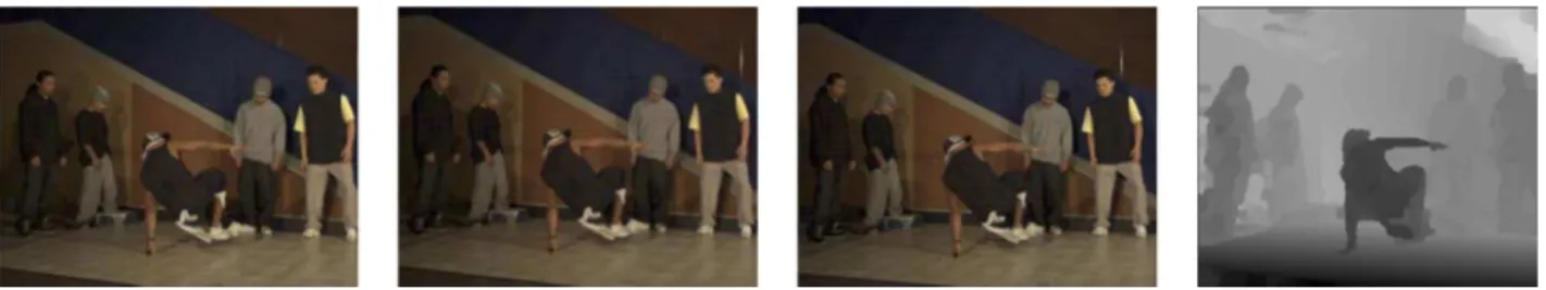
In the literature, the most popular methods for obtaining a dense depth field are approaches based on Markov random field (MRF) [9], [10] and partial differential equations (PDE) [11], [12]. Although these approaches derive from two different hypotheses, they end up with similar formulations, in which a cost function is minimized to arrive at the unknown dense depth field. A typical cost function consists of two terms; one favors intensity similarity for the desired depth values of different views, whereas the other implies smoothness between neighboring depth values. These two terms also approximate the depth distortion and number of bits to encode the resulting depth [9]. Therefore, minimizing such cost functions also yields rate-distortion optimal dense depth representations, addressing the requirements stated in Section I for accuracy and perceptual quality, and for compression. A typical example is shown in Fig. 2.
The multiview dense depth maps can efficiently produce 3-D replica of real scenes. They represent the whole scene with a single surface, making no distinction between separate objects; hence, they are easy to construct and space-efficient but in-capable of modeling the scene semantics. Graphical realism, progressive modeling, level of detail scalability and animation are fundamental functionalities which are hard to achieve using dense depth representations.
III. SURFACE-BASEDREPRESENTATIONS
In this section, we provide a comparative survey of various techniques and approaches which constitute the state-of-the-art in computer graphics for representing 3-D surface geometry.
These representation techniques can address most of the 3DTV requirements stated in Section I, including graphical realism, progressive modeling, level of detail scalability, and animation. We discuss four different surface representation paradigms: polygonal meshes, NURBS, subdivision surfaces, and point-based modeling.
A. Polygonal Meshes
Polygonal meshes are currently the most common 3-D repre-sentations in the manufacturing, architectural and entertainment industries. Polygons are also the basic primitives of hardware rendering technologies. The increasing demand for realism in computer graphics and the developments in 3-D scanning tech-nologies result in more complicated object meshes, containing millions of polygons; these can satisfactorily represent any geo-metric surface detail with almost no topological restrictions. Such complex meshes are very expensive to store, transmit and render; this has led to the development of many mesh simpli-fication and compression techniques resulting in flexible repre-sentations with different levels of detail and progressive quality.
Progressive Meshes: Most of the state-of-the-art mesh
rep-resentation techniques are based upon the progressive meshes (PM) scheme [13]. In the PM scheme, an arbitrary triangular mesh can be stored as a coarser mesh along with a sequence of mesh refinement operations referred to as vertex splits. A vertex split is a local elementary mesh transformation that adds a single vertex to the mesh. The PM representation of a surface defines a
continuous sequence of meshes with increasing accuracy. Each
mesh of the sequence corresponds to a LoD approximation spec-ified by a single vertex split operation.
The PM scheme naturally supports progressive transmission. However, as in all polygon-based representations, there is no inherent smoothness embedded in its description and polygonal artifacts appear along the silhouette boundaries, especially in the case of zooming and/or low resolution representations. One partial remedy to this problem, as proposed by Hoppe in [14], is to incorporate a view-dependent rendering and transmission strategy that can selectively refine a progressive mesh along its silhouette boundaries for a given view angle by making use of the locality of vertex split operations.
Progressive Forest Split Compression: The PM
representa-tion is not well suited for compression; the cost of a vertex split depends heavily on the size of the initial mesh, making the PM scheme impractical for very large meshes. The pro-gressive forest split (PFS) [15] and the compressed propro-gressive meshes (CPM) [16] are basically space-efficient versions of the PM scheme. In both methods, the vertex splits are grouped into
Fig. 3 Progressive time-varying meshes [22]. The 3-D Horse sequence at two levels of detail. Copyright © 2005, ACM, Inc. Reprinted by permission.
batches. In this way, the granularity of the progressive represen-tation is limited while the storage cost per triangle for encoding connectivity changes becomes independent of the initial mesh size.
3DMC coding of MPEG–4 v.2 [17] is mainly based on the PFS scheme, which encodes an arbitrary mesh, as a coarse mesh along with forest splits. The coarse mesh is compressed using topological surgery [18], which was also included in the VRML compressed binary format [19]. In the PFS scheme, the atomic refinement record is a group of vertex splits, that is, a forest split. This causes a compromise between compression and LoD granularity. In this way, the totality of vertex split operations is encoded at a much lower cost, but the resulting number of levels of detail is limited and the geometry cannot be locally refined. A direct consequence of this limitation is that a flexible view-dependent based rendering or transmission scheme cannot be implemented with 3DMC. We should finally note that both PM and PFS schemes have been extended to handle nonmanifold triangulations [20], [21].
Progressive Time-Varying Meshes: When modeling time-varying or deforming surfaces with meshes, it is much more space efficient to use a fixed connectivity for all frames of the animation and to modify only the vertex positions, rather than using a separate mesh for each time instant. However, the use of static connectivity often yields inadequate modeling of a deformable surface. Very recently, a progressive scheme has been proposed, which can efficiently produce incremental LoD approximations for all frames of a time-varying surface [22]. The scheme uses edge splits (or contractions) to refine (or simplify) the geometry of a given mesh. The edge contractions are clustered according to a base hierarchy that produces LoD approximations for the initial frame. The base hierarchy is then incrementally adapted to the geometry of the subsequent frames by using edge swap operations (see Fig. 3). The whole deforming surface can thus be encoded in terms of the initial vertex positions and the base hierarchy along with the swap sequence and the vertex displacements for each frame.
B. NURBS
Many shapes can be described by NURBS surfaces without loss of mathematical exactness. Since they are smooth and easily manipulated, the NURBS representation has long been
a common choice in computer aided design (CAD) or manu-facturing (CAM) and computer animation. A NURBS surface patch is represented by a function of two parameters, u and v, which defines a mapping of a 2-D region into the 3-D Euclidean space. It is usually expressed as the tensor product of some piecewise-polynomial basis functions (B-splines) and specified by a mesh of 3-D control points and two knot vectors (speci-fying the domain) over which the B-spline basis functions are defined. A point on a NURBS surface is given by
(1) where denotes the B-spline basis functions; : degrees (order) of the surface in and directions; : a mesh of control points; : weights. The knot sequences, and , are two nondecreasing sets of real numbers (knots), and partition the parameterization domain into subintervals:
and . The B-spline basis functions
are defined over these knot sequences and can be calculated in a recursive manner. Each knot of a knot sequence is associated to a control point and to a basis function calculated as above.
One of the key characteristics of a NURBS surface is that its shape is primarily determined by the positions of its con-trol points, and hence, the influence of each concon-trol point is local. This property is very desirable because it allows the oper-ator to make localized changes by moving only individual con-trol points, without affecting the overall shape of the surface. The shape of a NURBS surface and its smoothness can be con-trolled by the choice of knot vectors. In the most general case, the knot vectors can be nonuniform in the sense that the interval between two consecutive knots can vary inside a knot vector, yielding a nonuniform representation. The effect of a given con-trol point might also be different relative to another, depending on its weight; this is why NURBS is rational. In this respect, tensor-product uniform B-spline surfaces can be seen, as a spe-cial case of the general class of NURBS representation with uni-form knot vectors and equally weighted control points. A com-prehensive mathematical description of NURBS can be found in [23]; another article [24] provides an intuitive understanding of the functionality of NURBS (in particular curves) in practice.
Topological Limitations: The NURBS representation, as a
tensor product surface, can represent only planar, cylindrical or toroidal topologies. In order to overcome this restriction in prac-tice, a surface of arbitrary topological type is modeled as a net-work of NURBS or B-spline patches that are stitched together. One of the challenges in NURBS modeling is to define a patch-work structure and then merge the resulting patches seamlessly. A common tool to create NURBS models of arbitrary topology is NURBS trimming [25]; this is the most difficult and unreliable part of NURBS modeling, since seamless stitching of patches requires much labor and human intervention.
Surface Fitting: Manual, semi-automated, or automated
techniques can be used to fit NURBS surfaces to scanned 3-D objects of arbitrary topology. Automated techniques use constrained optimization to construct the surface patchwork and the parameterization. However, the automated techniques
Fig. 4. Uniform B-spline surface fitting [29]. Original polygonal mesh painted with patch boundaries, shaded B-spline surface patches (right half of the figure is the original mesh), and displacement mapped B-spline patches. Copyright © 1996, ACM, Inc. Reprinted by permission.
in the literature generally either have severe topological restric-tions [26], [27] or suffer from parameterization distortion and computational complexity [28]. Semi-automated schemes can partially address these drawbacks. Such a scheme is proposed in [29], which allows human interaction in both patch placement and B-spline patch fitting. In this scheme, the user roughly selects the outline of the rectangular patch boundaries by picking up successive vertices of an initial dense triangulation. These boundaries are automatically optimized, smoothed and represented in terms of B-spline curves. A uniform grid of 3-D points is then sampled over each patch and a B-spline surface is fit via unconstrained optimization by using a coarse to fine framework, as demonstrated in Fig. 4.
Smoothness: A NURBS surface has controllable smoothness
within a patch; in other words, the continuity (i.e., -times differentiability at every surface point) can be controlled by the degree of the basis B-spline functions and knot multiplicities. However, obtaining smoothness along patch boundaries is not straightforward. One solution is to define a built-in (tangent-plane) continuity at patch boundaries as in [28], which is visu-ally sufficient for a seamless patchwork structure. This is achiev-able only if uniform B-splines are employed, or if all patches are forced to have the same knot vector and the same order; but these restrictions limit the ability of the general NURBS repre-sentation to deal with fine surface details.
Representing Fine Detail: One of the major drawbacks of
NURBS modeling is its inefficiency in representing fine sur-face details. Local refinement of a NURBS sursur-face necessitates large-scale modification. In order to add a single control point within a patch, an entire column or row of control points must be split to preserve the desired quadrilateral grid structure. This situation may even produce a more global effect, which propa-gates into the whole patchwork structure if, for example, there is a built-in continuity setting. One solution is to make use of dis-placement maps as proposed in [29]; these model and store the fine detail as if it were a kind of texture information, and then map it onto the surface during rendering. The schemes based on displacement maps are also useful to separate fine detail from coarser semantics for animation and editing purposes.
Another possibility for modeling fine detail is to use chical B-splines [26]. However the schemes based on hierchical B-splines are not sufficiently generalized to work with ar-bitrary complexity and topology; they seem to be more efficient in editing and refining computer generated models for which they can provide valuable coarse manipulation semantics.
Fig. 5. Interpolating subdivision [33]. The initial semi-regular coarse mesh and the smooth limit surface obtained by modified Butterfly subdivision. Copyright © 1996, ACM, Inc. Reprinted by permission.
Level of Detail: Theoretically, a NURBS surface has infinite
resolution. In practice however, it is tessellated into either a tri-angular or quadrilateral representation before rendering. This is achieved by stepping through the - and -domains and eval-uating the NURBS equation for points on the surface. Such an evaluation produces a grid of sample points at a desired level of detail; these can then be easily converted into a mesh representa-tion. The built-in LoD control of NURBS surfaces does not how-ever imply a real incremental LoD representation. A NURBS surface is a compact representation and its LoD hierarchy can be constructed only if the complete representation is available.
C. Subdivision Surfaces
Subdivision surfaces have gained attention in the last decade, as a possible alternative to NURBS and traditional polygonal representations. The main challenge is to unify these two ex-tremes of 3-D modeling in an infrastructure that allows repre-sentation of arbitrary topology and any fine detail with a more controllable smoothness. In subdivision schemes, the basic idea is to construct a surface from an arbitrary polygonal mesh by recursively subdividing each face. If the subdivision is done ap-propriately, the limit of this sequence of successive subdivision will be a smooth surface. For example, the well-known Cat-mull–Clark [30] subdivision scheme yields a bicubic B-spline as the limiting surface.
Subdivision schemes in the literature can be classified on the following three criteria: the pattern of the refinement rule (vertex insertion [30]–[33] or corner cutting [34]), the type of generated mesh (triangular [31], [33] or quadrilateral [30], [32]), whether the scheme is approximating [30], [31] or interpolating [32], [33]. One of the simplest subdivision schemes is the Loop scheme for triangular meshes, which uses vertex insertion for refinement [31]. The refinement proceeds by splitting each tri-angular face into four subfaces. The vertices of the refined mesh are then repositioned by using weighted averages of the ver-tices in the initial mesh. Vertex insertion schemes can be in-terpolating or approximating; in the first approach, the original control points, i.e., the mesh vertices, are also points of the limit surface. Interpolating schemes are attractive, since they allow control of the limit surface in a more intuitive way (see Fig. 5). On the other hand, the quality of surfaces produced by approx-imating is higher and they converge to the limit surface faster.
Subdivision schemes give at least smoothness, even in irregular settings [35] and the smooth limit surface can be computed explicitly without need for infinite subdivision recursion [36]. To deal with irregular meshes, semi-uniform subdivision schemes make a distinction between regular and irregular (extraordinary) vertices. Extraordinary vertices of a semi-regular mesh (i.e., a mesh made up of mostly regular vertices) are those with valence other than 6 for the triangular case and 4 for the quadrilateral case. In order to guarantee smoothness, extraordinary vertices are treated differently and the subdivision coefficients at these vertices vary depending on their valences [33].
Multiresolution Analysis-Synthesis: With subdivision schemes, it is possible to build a multiresolution mesh pyramid that allows one to coarsen a given mesh, and later refine it as de-sired, in order to always recover the same mesh with the same connectivity, geometry and parameterization. By reversing the subdivision process, i.e., by repeatedly smoothing and downsampling, an irregular coarse base mesh can be obtained from an initial dense mesh along with its smooth intermediate representations.
The geometrical information which is lost due to smoothing can be incorporated into the subdivision process by encoding the difference as detail offsets [37], [38]. Once this is achieved, the initial mesh can be recovered from the coarse mesh by repeated subdivisions and by adding the detail offsets. This process is re-ferred to as multiresolution analysis and synthesis. The recorded details can be introduced at any time independent of the others and propagated smoothly, as the surface is refined or coarsened. Multiresolution analysis also allows the construction of an efficient progressive representation which encodes the original mesh with a coarse mesh and a sequence of wavelet coeffi-cients expressing the detail offsets between successive levels. There are several methods for building wavelets on semi-reg-ular meshes [39], [40]. These schemes are particsemi-reg-ularly effective for compression of densely sampled, highly detailed surfaces. However, when the input geometry to be compressed is already well-described by a compact simplified mesh, the space effi-ciency of subdivision schemes becomes questionable.
Subdivision Connectivity and Remeshing: A mesh, generated
from an initial mesh of arbitrary connectivity by successive sub-division, is said to have subdivision connectivity. Such meshes are semi-regular meshes, made up of mostly regular vertices ex-cept for some isolated extraordinary vertices. Most of the tech-niques based on subdivision surfaces are applicable only to the meshes having subdivision connectivity, such as the multireso-lution analysis-synthesis scheme described in the previous sub-section. However, mesh representations, especially those gen-erated from scanned 3-D data, do not have this property. The literature has various remeshing techniques [41]–[43], which can convert an arbitrary mesh into a form with subdivision con-nectivity. This necessitates finding a new parameterization of the underlying surface, represented by the initial arbitrary mesh over a much coarser simplified version (base domain). Hence, by remeshing, the connectivity but not the geometry of the mesh is modified. Remeshing is a computationally costly task, and in practice, cannot be achieved without introducing some distor-tion to the geometry of the original mesh.
Fig. 6 Multiresolution mesh editing [37]. (Above) Original cow and its edited version. (Below) Editing sequence for the leg: original, coarsest scale, edit, and reconstruction with multiresolution details. Copyright © 1997, ACM, Inc. Reprinted by permission.
Multiresolution Editing: Once a multiresolution mesh pyramid has been constructed for a subdivision surface, it can be edited at any available resolution level in the same manner that the surface details are introduced [37] (see Fig. 6). The changes (e.g., by clicking on a vertex and dragging with the mouse) introduced on a coarser level propagate smoothly towards finer levels, or vice versa. This provides valuable ma-nipulation semantics that can be used in animation, deformation or surface design. Subdivision surfaces are already being used in commercial applications, especially for animation purposes. A famous example is the animated short film Geri’s Game, by
Pixar [44]; won Oscar for the best animated short film in 1997. Nonuniform Subdivision: The subdivision connectivity property, a requirement for most multiresolution techniques based on subdivision, is an important limitation. The pioneering work presented in [45] combines a variety of the techniques in the literature and extends the multiresolution analysis-synthesis scheme to irregular meshes with no need for remeshing; thus multiresolution signal processing techniques, such as editing, smoothing, enhancement and texture mapping, also become applicable in the irregular setting. This generality is basically achieved by defining a nonuniform subdivision scheme, where the weighting coefficients depend not only on the connectivity, but also on the geometry. In practice, these techniques work quite well, however, their analytical smoothness is not com-pletely known at present.
D. Point-Based Modeling
Surface points [46], [47], particles [48], or surfels [49] can be used instead of triangles (or polygons), as simpler display prim-itives for surface representation. The terms “particle” or “surfel” are used in the literature to denote a dimensionless space point that has context-dependent surface properties, such as surface normal or color. In point-based schemes, the surface geometry is represented by a set of points sampled from the surface; no topology or connectivity information is explicitly stored. Hence,
point sets do not have a fixed continuity class, nor are they lim-ited to a certain topology, as are many other surface representa-tions; therefore they represent any shape with arbitrary topology and complexity. In the most general setting, the distribution of sampled points is nonuniform; however the point set can easily be forced to be sampled on a discrete grid. Uniformly sampled point sets are much easier to handle, compress and render, since they implicitly impose some neighborhood information.
The idea of using points, instead of triangle meshes and textures, was first proposed by Levoy et al. [46]. For more than a decade, point-based modeling was used mostly to model phenomena that are difficult to model with polygons, such as smoke, fire and water. With the recent advances in scanning technologies, the ability of 3-D models to represent real objects has increased tremendously but processing such huge meshes produces bottlenecks with current technology. As a result, point-based representation systems have regained attention in the last half-decade. Rendering complexity is one of the most problematic issues. When a highly detailed complex 3-D triangle model is rendered, the projected size of individual triangles is often smaller than the size of a pixel in the screen image. In this case, the polygon rasterization process at the rendering pipeline becomes unnecessarily costly, whereas rendering individual points, rather than polygons, can be much more efficient.
Octree Particles and Qsplat: A progressive point-based
sur-face-modeling technique was first proposed by Yemez et al. [50], [51]. This technique is based upon a hierarchical octree structure, which first voxelizes the surface geometry at different levels of detail and then encodes it in terms of octree particles that are uniformly sampled over the surface. The particles are encoded in such an order that the viewer, or the decoder, can progressively reconstruct the surface information and visualize it by on-the-fly triangulation and polygon rendering. In two very closely related works, Rusinkiewicz et al. [52], [53] followed the framework presented in [50], and proposed a point-based technique to render their large data sets resulting from the
Dig-ital Michelangelo Project [54]. Rather than an octree
represen-tation, they constructed a sphere hierarchy and rendered the re-sulting representation via splatting. Splatting allowed them to implement a progressive interactive representation that can be locally refined with respect to viewing parameters.
Since then, several other progressive schemes have been pro-posed, all based on hierarchical data structures [51]–[53], [55]. When sampled on a regular grid, such as octree, the point sets can easily support progressive transmission/visualization and LoD scalability with no additional explicit refinement informa-tion. Very recently, the authors of [56] have proposed a progres-sive point-based scheme that is also applicable to nonuniformly sampled surface points in a framework that is very similar to subdivision surfaces and the PM scheme.
Compared to triangle meshes, point-based representations seem to be more efficient regarding storage and memory for progressive modeling of high resolution surface geometry; this is because only sample point coordinates need to be stored and they do not require additional structural information such as connectivity. For instance, the storage requirements for a uni-formly distributed high resolution point dataset can be reduced
Fig. 7. Surface splatting examples [58]. Copyright © 2001, ACM, Inc. Reprinted by permission.
by up to about 2 bits per sample by using hierarchical structures [55], [57]. However, low-resolution approximations of point sets do not generally produce realistic rendering results.
Splatting: Point rendering can be viewed as a resampling
problem. When surface samples are projected from the object space onto the image space, the projections do not usually co-incide with the regular grid of the output image. If this process is not properly handled, visual artifacts, due to aliasing and un-dersampling, might appear. Point rendering basically consists of reconstruction of a continuous surface from the input sam-ples, filtering the continuous representation, and sampling it (or evaluating it) at the output positions.
Most point-based rendering systems use splatting to achieve high quality renderings [49], [52], [55], [58]–[61] (see Fig. 7). The basic idea in splatting is to associate each surface point with an oriented tangential disc. The shape and size of the disc may vary; if it is circular, it projects as an elliptical splat on the image plane and its radius can be adjusted with respect to the local density. The shade or color of the point is warped accordingly so that its intensity decays in the radial direction from the center. The shape of the splat together with its intensity distribution defines the reconstruction kernel, or so-called
foot-print. Often a single image pixel is influenced by several
over-lapping splats; in this case the shade of the pixel is computed by the intensity-weighted average of the splat colors. Proper filtering is needed at the end to avoid aliasing artifacts. The choice of the splat shape and distribution often yields a compro-mise between rendering quality and performance; Gaussian cir-cular splats usually perform well. Other more sophisticated non-Gaussian kernels could also be used at the cost of an increase in rendering time [62]. Even without special hardware support, current splatting techniques can achieve very high quality ren-dering of point-based surface models at a speed of millions of points per second.
Point-Based Animation: Points (or particles) have been
suc-cessfully used to animate complex phenomena, such as smoke, fire and water, using dynamic particle systems with inter-par-ticle forces. This literature already offers a framework to those interested in point-based computer graphics for animation and editing. Currently, there are very few works and systems that ad-dress point-based animation [63] (see Fig. 8) and editing [64]. These systems are far from mature, but worthy of attention. For example, Pointshop 3-D is an interactive editing system [64], which is also available as a modular software platform and im-plementation test-bed for point-based graphics applications. It provides a set of kernel functions for loading, storing, modi-fying, and rendering point-sampled surfaces.
Fig. 8. Point-based animation with an elasticity model driven from continuum mechanics [63] Copyright © 2004, ACM, Inc. Reprinted by permission.
Fig. 9. Illustration of data structures implementing volumetric representations. (left): voxel buffer. (right): octree.
IV. VOLUMETRICREPRESENTATIONS
The notion of volumetric representation refers to parameteri-zation of the reconstruction volume in a world reference frame. The representation may contain data associated to any location within a volume of interest. The unit volume, defined by a reg-ular parameterization of the space, is called a voxel and cor-responds to the smallest representable amount of space [65]; therefore, it determines the precision of the representation..
The data associated with a voxel refers to the properties of the surface segment that occurs within it, or else, occupies it. Empty voxels are typically not associated with any informa-tion other than a Boolean flag indicating that they are vacant. Thus, voxel representations might be quite memory-inefficient, since the utilized data usually take up only a small portion of the representation capacity. Straightforward implementation of a voxel space is through a volume buffer [1], or cuberille [66], employing a 3-D array of cubic cells. Other implementations utilize data structures that omit the representation of voxels that are empty, or cannot be observed.
A common implementation of the above idea is called an
oc-tree [67] (see Fig. 9). Starting from a coarse resolution, it
facili-tates the detection of large empty areas; the resolution is refined only for the areas that contain surfaces. The data structure con-sists of a tree that grows in depth, but only at the nodes that correspond to occupied voxels; it recursively subdivides the ini-tial voxel into eight parts of equal size and terminates at a pre-defined resolution. In this process, a tree is generated that rep-resents the occupied voxels. Octrees exhibit greater represen-tational efficiency over volume buffers and they are the most common method of storing voxels, providing both good data compression and ease of implementation. Some variations of this approach are linear octrees [68], PM-octrees [69], kd-trees
[70], and interval trees [71]. In addition, nested multiresolution hierarchies are also utilized in [72].
Conceptually, binary space-partitioning trees [73] are sim-ilar to octrees except that each subdivision is binary and seg-ments the volume by a plane of arbitrary orientation. The sub-division terminates at a predetermined threshold of spatial reso-lution. This approach requires larger memory capacity than oc-trees but less than volume buffers. However, it is not inherently compatible with a regular parameterization of the reconstruc-tion volume, which facilitates transmission and rendering.
Multiview stereo techniques aim to reconstruct a 3-D scene from multiple images that are simultaneously acquired from different viewpoints. In multiview stereo, there is no notion of a single “depth” dimension; for arbitrary camera locations, there is no semantic difference between and directions. Vol-umetric representations are valuable, especially in multiview stereo-reconstruction algorithms, because they provide a common reference frame in which the results obtained from different views are combined [74]–[76]. Volumetric representa-tions also include neighborhood information, meaning that they facilitate direct access to neighboring voxels. This property is essential for efficient computation of visibility- the requirement that voxels lying between the camera and an imaged surface be empty. This computation is essential in space-carving [77] and voxel-coloring [78] approaches, where the reconstruction result is obtained implicitly by detecting the empty voxels. Moreover, the access to neighborhood information facilitates operations such as 3-D convolution and detection of connected components; these are both useful operations for computa-tion of local geometric properties (e.g., curvature [79]), as well as for noise-filtering of the reconstruction results. Based on a volumetric representation of the reconstruction, radial basis functions (RBF) can provide smooth interpolations and noise-filtering of the data [80], [81]. In RBF approaches, after a functional is computed for each voxel, the surface is extracted as an iso-surface by using either the Marching Cubes algorithm [82] or a surface-following [81] variation of this technique.
An advantage of voxel-based representations is their linear access time for the structured data. This property could be useful for efficient rendering of surface representations, independently from the complexity of the object. Furthermore, depth-sorting of voxels for application of the GPU-accelerated Z-buffering algorithm [83] is handled well. On the down side, voxels are rendered as cubes, resulting in poor visualization when the ren-dering viewpoint is close to the surface. In contrast, polygons produce continuous renderings of the reconstructed surface. In addition, the architecture of commodity-graphics hardware is designed to render polygons; mesh-based representations are therefore handled better. The straightforward conversion of a volumetric representation to a mesh is possible, e.g., by replacing each facet of the voxel with two triangles [84]; this is not however very useful since the result is not optimized in terms of memory capacity and the resulting geometrical structure is still shaped as an arrangement of cubes. Finally, voxel-based representations facilitate data-partitioning into subvolumes for parallel processing by more than one CPU [85] and exhibit a predetermined accuracy proportional to the third power of the resolution of the model stored in memory.
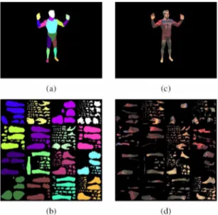
Fig. 10. Single texture atlas representation: (a) color coded body parts, (b) corresponding regions in texture space, (c) input frame, (d) resampled texture frame considering visibility [86]. Copyright © 2004, IEEE, Inc. Reprinted by permission.
V. TEXTUREREPRESENTATIONS
Texturing of 3-D geometric objects is essential for realistic scene rendering in 3DTV applications. The texture of a real ob-ject is usually extracted from a set of images that capture the surface of the object from various angles. These images can ei-ther be processed and merged into a single texture representation or stored separately to be used as multitextures.
A. Single Texture Representation
Single textures can occur in closed form, representing the appearance of the entire object surface by a single connected area. This is achieved by unwrapping the true object surface, i.e., by transforming it to a 2-D plane approximation. The tex-ture information is stored in the form of a 2-D rectangular image which can then be coded and transmitted along with surface ge-ometry information and eventually mapped onto the object sur-face during rendering. Single textures may also exist in open form, such as a texture atlas, where the image texture contains isolated texture patches for each part of a 3-D object [86], as shown in Fig. 10. Although closed-form texture representations can achieve higher compression ratios due to high correlation within the 2-D texture image area, they cannot be generalized to handle objects with arbitrary topology. A texture atlas on the other hand, can model the appearance of a surface with no re-striction on topology. However, it is not as space efficient as closed form textures, since the 2-D texture image contains iso-lated texture parts with limited correlation. For both single tex-ture representations, the appearance is static in terms of different lighting and reflection effects during navigation.
B. Multitexture Representation
Multitexturing was originally developed by the computer graphics community to apply environmental effects such as special lighting or reflection properties, to an image texture. In this case, the utilized set of textures consists of the original
Fig. 11. Multitexture example with (view-dependent) weighted original camera views mapped onto 3-D geometry.
texture, plus a number of artificial textures, representing illu-mination and reflection effects. In contrast to this approach, recent developments in multicamera scenarios have led to the concept of multitexturing as a computer vision approach, where “multitexture” refers to a number of original camera views of a common 3-D scene object [87]. Multitextures include the envi-ronmental effects, as they appear in the original camera views. Hence, the naturalness of the rendered object mainly depends on the camera density and the interpolation strategy between original views. Fig. 11 shows a multitexturing example. For view-dependent texturing, there are different approaches, such as light field rendering [88], [89], light field mapping [90] or unstructured lumigraph rendering [91]. An overview of view-dependent texturing approaches can be found in [92].
VI. PSEUDO-3-D REPRESENTATIONS
The term pseudo-3D refers to image-based representations that avoid using any explicit 3-D geometry to obtain a 3-D im-pression from 2-D video. Following the taxonomy in [93], a 3-D view can be composed from the input sequences by using ei-ther implicit geometric information or no geometric information at all. In this section, some representations obtained by image interpolation and image warping, as well as light field repre-sentations, are briefly summarized. Actually, the borderline be-tween other representations is quite vague, since some of these methods employ techniques described in the previous sections. Chen et al. create virtual views of still images by image-based interpolation [94], whereas Seitz et al. present physically cor-rect view-morphing in their seminal paper [95]. In contrast, in image warping the virtual viewing position is not restricted to the baseline, which is the line between two camera centers. An example of such a method is the trifocal transfer that allows wide extrapolations from two or three closely positioned cam-eras [96]. All the aforementioned methods implicitly employ the available geometric information by utilizing the corresponding feature points between the images.
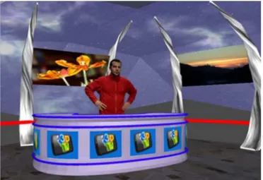
More recently, the domain of time-varying representations has also been studied; image interpolation of the objects in dy-namic scenes is investigated in [97] and [98]. Some of the in-terpolation methods could be used for applications in sports TV transmissions and can thus be regarded as a pioneering pseudo-3DTV application [99]. In [100], natural video objects obtained by image warping are augmented with synthetic content by the help of MPEG-4 standard; this could also be an important tool in 3DTV applications (see Fig. 12).
Fig. 12. Pseudo 3-D video object augmented with a synthetic environment.
In a different approach, a light field or lumigraph is a 4–D simplification of the plenoptic function, as described by Adelson and Bergen in [101]. This concept was independently intro-duced both by Levoy et al. in [88] and Gortler et al. in [102]. In this technology, virtual views are obtained by interpolation from a parameterized representation that uses coordinates of the in-tersection points of light rays with two known surfaces. Light fields are often sampled by using large camera arrays. Dynamic light fields extend the function by the time dimension, which is essential for 3DTV applications. The most crucial issue in sam-pling dynamic light fields is the large volume of data. Hence, compression of such representations is investigated in [103] and [104]; the latter addresses the problem by using distributed light field rendering. However, the research direction in light field rendering leans towards using more sparsely arranged cameras and additional scene information, such as geometric proxies; this obviously leads to other scene representation methods that are covered in the other sections of this paper.
VII. OBJECT-BASED3-D SCENEMODELING
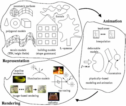
3-D dynamic scene modeling involves three basic tasks:
rep-resentation, animation, and rendering (see Fig. 13). The
re-search efforts in the field of computer graphics have already produced diverse techniques for realistic scene modeling that are amenable to real-time implementations and thus well suited for 3DTV applications.
A. Representation
A typical 3-D scene may contain moving objects of different types and complexities. The choice of the best surface represen-tation scheme for a given object depends on its geometry, appear-ance and motion. A typical example for such 3-D scenes is an
out-door environment that comprises static urban scenery with living
moving objects. Once a static scene for an outdoor environment is constructed, only any additional living objects need to be mod-eled, as dynamic components of this scene. In the literature, there are different building representations that can be used to model urban scenery and different ways to populate them to construct
urban scenery [105], [106]. Similarly, there are different repre-sentations for terrain data, such as height fields and triangulated irregular networks [107]. These components could be integrated for a time-varying representation of the scenes captured using multiple cameras and/or multiple views.
As explained in Section III, the surface of any 3-D object can be approximated via polygons, parametric surfaces or point sets at increasing levels of accuracy. However, the methods based on Euclidean geometry, such as polygonal approximations, cannot describe typical natural objects, such as mountains, clouds, and trees, since these objects do not have regular shapes; their irreg-ular or fragmented features cannot be realistically modeled by these methods [108]. As a solution to this shortcoming,
fractal-geometry describes procedures to model natural objects, such
as mountains, clouds, trees [109]. Lindenmayer systems (L-sys-tems) can also be used for the realistic modeling of plants, since they define complex objects by successively replacing different parts of simple initial objects in parallel using a set of rewriting rules [110].
B. Animation
Computer animation makes use of computers to generate both key-frames and the frames in between. Animating a 3-D model can be regarded as generating the values of the model parameters over time. The models have various parameters, such as polygon vertex positions, joint angles, muscle con-traction values, colors, and camera parameters. Animation is a process of varying the parameters over time and rendering the models to generate the frames. After the key-frames are generated, either by directly manipulating the models or by editing the parameter values, interpolation techniques, such as linear interpolation and spline interpolation, can be used to generate in-between positions [111], [112].
Recently, physically based modeling and animation has emerged as a new approach in computer animation [113]. The methods for modeling the shape and appearance of objects are not suitable for dynamic scenes where objects are moving. These models do not interact with each other or with external forces. In real life, the behavior and form of many objects are determined by such physical properties as mass, damping, and the internal and external forces acting on them. The deformability of the ob-jects is determined by the properties of elasticity and inelasticity (such as internal stresses and strains) inherent in the material.
For realistic animation, one should model the physical prop-erties of the objects to follow predefined trajectories and interact with the other objects in the environment, just like real physical objects. Physically based techniques achieve this kind of natural animation by adding physical properties to the models, such as forces, torques, velocities, accelerations, mass, damping, kinetic and potential energies, etc. Physical simulation is then used to produce animation based on these properties. The initial value
problems must be solved so that the new positions and velocities
of the objects are determined by the initial positions and veloc-ities, and by the forces and torques applied to the objects.
Constraints provide a unified method to build and animate
ob-jects by specifying their physical behavior in advance without specifying their exact positions, velocities, etc., [114], [115].
Fig. 13. Basic tasks involved in modeling of a dynamic 3-D scene that includes objects of different types: representation, animation, and rendering.
Thus, given a constraint, one must determine the forces to meet and maintain the constraint. Some examples of constraints used in animation are the point-to-nail constraint, which is used to fix a point on a model to a user-specified location in space; the
attachment constraint, which is used to attach two points on
different bodies to create complex models from simpler ones; the point-to-path constraint, which requires some points on a model to follow an arbitrary user-specified trajectory; the
ori-entation constraint, which is used to align objects by rotating
them, etc., [116].
An important aspect in realistic animation is modeling the be-havior of deformable objects. This uses methods from elasticity and plasticity theory. However, such techniques are computa-tionally demanding, since their simulations involve the numer-ical solution of the partial differential equations that represent the shape and motion of the deformable object through time [117]. For simulating the behavior of deformable objects, one should approximate a continuous model by using discretization methods. The trajectories of the points are determined by the properties of the deformable object. For example, in order to obtain the effect of an elastic surface, the grid points can be connected by springs. In fact, mass-spring systems are one of the simplest, yet most effective ways, to represent deformable objects.
There are two well established formulations to simulate the dynamics of elastically deformable models- primal [117] and
hybrid [118]. These formulations use concepts from elasticity
and plasticity theory; they represent the deformations by using such quantities from differential geometry as metric and curva-ture tensors. There are other approaches for deformable models:
mathematical constraint methods, based on physics and opti-mization theory [114]; nonrigid dynamics, based on modal anal-ysis that discards high-frequency modes having no effect on linear deformations and rigid body dynamics to reduce the di-mensionality and stiffness [119]; nonrigid dynamics, based on simple linear global deformations with relatively few degrees of freedom [120]; constraint methods for connecting dynamic primitives that can be globally deformed (bends, tapers, twists, shears, etc.,) to make articulated models [121].
C. Rendering
The rendering literature is enormous; discussing all the ren-dering techniques is beyond the scope of this paper. For the pur-poses of 3DTV, we will concentrate on the techniques that are suitable in hardware implementations.
Rendering techniques try to model the interaction between light and the environment to generate pictures of scenes. This could be in the form of the Phong Illumination Model [122], which is a first order approximation to the rendering equation [123], or it could be very sophisticated techniques, such as ray tracing, radiosity, or photon mapping. Simple local illumination models do not consider the interaction of light with the envi-ronment, such as object-to-object light interactions (reflections, transmissions, etc.,). They only calculate the direct illumination from light sources on object surfaces.
Global illumination models calculate object-to-object inter-reflections, transmission, etc., to generate more realistic ren-derings, but they are computationally expensive. Ray tracing [124], [125] can only handle specular reflections, where the light
sources are point light sources. There are however some vari-ations of ray tracing, such as distributed ray tracing, that in-crease the realism of the rendering by firing more rays to add spatial antialiasing, soft shadows, depth-of-field effects [126]. Radiosity [127] can only handle diffuse reflections and is useful for rendering room interiors; this is important for architectural walkthroughs. There are attempts to combine ray tracing and radiosity, but these attempts are only partially successful de-pending on the assumptions about the rendered scenes [128].
There are also some new approaches to global illumination of scenes, such as photon mapping that can make realistic rendering more affordable. Photon mapping uses forward ray-tracing (i.e., sending rays from light sources) to calculate reflecting and refracting light for photons [129]. It is a two-step process (distributing the photons and rendering the scene) that works for arbitrary geometric representations, including parametric and implicit surfaces; it calculates the ray-surface intersections on demand.
In general, rendering techniques are classified into two groups: object-space and image-space. Object-space tech-niques calculate the intensity of light for each point on an object surface (usually represented by polygonal approxima-tions) and then use interpolation techniques to interpolate the intensity inside each polygon. Scan-line renderers, such as flat shading, Gouraud shading [130], and Phong shading, are in this category and they use local illumination models, e.g., the Phong Illumination Model, to calculate intensities at points. Radiosity is also an object-space technique. However it is a global illu-mination algorithm that solves the rendering equation only for diffuse reflections. Image-space techniques calculate intensities for each pixel on the image. Ray tracing is an image-space algorithm, which sends rays to the scene from the camera through each pixel and recursively calculates the intersections of these rays with the scene objects. The techniques, such as texture mapping [131], [132], environment mapping [133], and bump mapping [134], add realism to 3-D scenes, since the scenes are not usually uniformly shaded. Such techniques are not computationally intensive compared to global illumination algorithms and can be used together with scan-line renderers. Moreover, they can be implemented in real-time on GPUs.
In order to render a 3-D scene, the parts that are visible for different views must be calculated. This step requires the elim-ination of hidden surfaces. Some rendering algorithms, such as ray tracing and radiosity, handle the visible surface problem im-plicitly. It is handled explicitly by scan-line renderers, such as Gouraud and Phong shading, (e.g., using z-buffer).
VIII. HEAD ANDBODYSPECIFICREPRESENTATIONS
Human faces and bodies form an integral part of most dynamic 3-D scenes. Therefore, the 3-D representation of the human face and body merit special attention in different scene representation technologies for 3DTV.
A. Modeling the Skeleton and the Body Appearance
Several articulated 3-D representations and mathematical for-mulations have been proposed to model the structure and move-ment of the human body. A human body model (HBM) can
be represented as a chain of rigid bodies, called links, inter-connected to one another by joints. Links are generally repre-sented by sticks [135], polyhedrons [136], generalized cylin-ders [137] or superquadrics [138]. A joint connects two links by means of rotational motions around their axes. The number of independent rotation parameters defines the degrees of freedom (DOF) associated with a given joint. Development of a highly realistic HBM is a computationally expensive task, involving a problem of high dimensionality. In computer vision, where models need to be only moderately precise, articulated struc-tures with low DOF are generally adequate [138], [139]. But, in computer graphics, highly accurate representations consisting of more than 50 DOF are usually desired [135].
The models proposed for the body appearance can be classi-fied into four categories: stick figure models, surface models, volume models, and multilayer models. Stick figure models [140] are built by using a hierarchical set of rigid segments, connected by joints; they allow for easy control of movement, but realism is limited. Surface models are based on two layers: a skeleton, which is the backbone of the character animation, and a skin. The skin can use different types of primitives: points and lines, polygons [141], curved surface patches [142], [143], and subdivision surfaces [44]. In volumetric models, simple volumetric primitives, such as ellipsoids, spheres and cylinders [144] or implicit surfaces [141], [145] are used to construct the shape of the body. They perform better than surface models but it is difficult to control a large number of volumetric primitives during animation. Multilayer models consist of three layers:
skeleton, muscle and skin. Complex motions are produced
easily by building up the animation in different layers. Chad-wick et al. were the first to use a muscle layer [146]. Nedel and Thalmann simulated muscles by a mass-spring system composed of angular springs [147].
B. Motion of the Skeleton
There are a number of ways to mathematically model an ar-ticulated human body using the kinematics and dynamics ap-proaches. A mathematical model that describes the parameters of the links and the constraints associated with each joint is called a kinematics model and it can only describe the possible static states of a system [146], [148], [149]. In a dynamic model, the state vector includes positions, linear and angular veloci-ties, accelerations, and the underlying forces and torques that act on this model [150], [151]. Dynamic model-based approaches are used to realistically animate walking models. However, dy-namic model-based techniques are computationally more costly than kinematics-based techniques.
Determining the motion parameters explicitly at each frame, even for a simple motion, is not a trivial task. The solution is to specify a series of key-frame poses and interpolate the joint pa-rameters between those key-frames [152]. Linear interpolation is the simplest method of generating the intermediate poses, but it produces a robotic motion due to discontinuous first deriva-tives in the interpolated joint angles. Obtaining smooth velocity and acceleration requires higher order interpolation methods, such as piecewise splines [153].
Since dynamics simulation cannot solve all animation problems, motion capture techniques have been introduced
to animate virtual characters from real human motion data. Motion capture methods are mainly used in the film and com-puter-game industries. The motion of a real actor is captured by tracking the 3-D positions and orientations of points lo-cated on him, using mechanical, electro magnetic or optical technologies [154], [155]. This method produces realistic and highly detailed motion in a short time. Since many application scenarios require no visual intrusion into the scene, researchers in computer vision have also investigated marker-free optical methods [156].
HBM can be described in various ways but for human body models to be interchangeable, a standard for animation is re-quired. The Web 3-D H-anim [157] standards for human repre-sentation and the MPEG-4 reprerepre-sentations for facial and body animation have been developed to meet this need [158].
C. 3-D Face Modeling and Animation
It is a major challenge to accurately model and animate the expressive human face using a computer [159]. Computer fa-cial animation follows two basic steps: designing a 3-D fafa-cial mesh and animating that mesh to simulate facial movements. A face model with reasonable quality will typically consists of approximately 500 vertices. 3-D mesh can be designed in-teractively using computer graphics software or it can be cap-tured via specific techniques. A general 3-D capturing tech-nique uses photogrammetry, employing several images of the face, recorded from various angles [160]. Another technique is to place markers on the face that can be observed from two or more cameras. A more recent and accurate technique uses an automated laser scanner to digitize a person’s head and shoul-ders in just a few seconds.
The literature on facial animation can be classified into three major methods: muscle-based [161], [162], rule-based (geometrical) [160], [163], and motion capture-based [164]. Muscle-based facial animation techniques can be further di-vided into two categories- physics-based muscle modeling and modeling with pseudo or simulated muscles. Physics-based muscle modeling mathematically describes the properties and behavior of human skin, bone and muscle systems by using mass-spring systems [165], vector representations [166], or layered spring meshes [167], [168]. Pseudo-muscle models mimic the dynamics of human tissue with heuristic geometric deformation of splines [169], [170] or free form deformations [171]. Physics-based muscle modeling produces realistic re-sults by approximating human anatomy. However, the high computational cost of physics-based muscle modeling is a problem for real-time applications.
In rule-based facial animation [160], [172], a subset of the nodes of the geometry mesh, called feature points, is used to control the movement of the rest of the nodes of the geometry mesh. Although rule-based methods provide real-time deforma-tions of the face, they may lack realism, as they are not based on any physical model. In [160], a rule-based animation method is used, where the face model consists of a dense geometry mesh and a sparse shape mesh. As part of the personalized 3-D face model, geometry mesh definitions conforming to each action state of the face are obtained. The facial expressions comply
with the MPEG–4 standard [173] and are joy, sadness, anger, fear, disgust, and surprise. Visemes are defined manually; these define the lip shapes corresponding to the phonemes of speech. A shape interpolation approach animates the face over time by averaging and blending visemes and expressions according to predefined weights. Fig. 14 shows the facial expressions for a female character. Typical examples for lip-synchronized facial animations can be accessed in [174].
IX. STANDARDS FOR3-D SCENEREPRESENTATIONS
Interoperability is an important requirement, especially for the development of mass-consumer products in media-related industries. Therefore, open international standards play a key role in the success of new media technology. Standardized for-mats for media content enable interoperability between different systems, while still allowing for competition among equipment and service providers. The International Organization for Stan-dardization (ISO) is an important body that provides format specifications for media content.
The Virtual Reality Modeling Language (VRML), released in 1997, is an ISO standard for 3-D scene representations [175]. It was mainly developed for the exchange of 3-D computer graphics data over the Internet. Although VRML provides a lot of useful elements, it has limited applicability for 3DTV applications because of limited real-time capabilities, and the lack of efficient point-based and other representations. Re-cently, ISO ratified the Extensible 3-D (X3D) [176] standard, as a successor to VRML; this was developed by the Web3D Consortium [177]. It provides improved real-time capabilities, including video and audio, as well as sophisticated computer graphics elements. The main focus of the design however, is still on computer-type systems and applications.
Standards for consumer electronics and telecommunication are developed by ISO/IEC JTC 1/SC 29/WG 11 (Moving Picture Experts Group—MPEG) and ITU-T SG 16 Q.6 (Video Coding Experts Group—VCEG) often in joint efforts resulting in joint specifications. With MPEG–4, for the first time, a universal multimedia framework has been created, which effi-ciently integrates natural video and audio with 3-D computer graphics [178]. MPEG–4 combines real-time streaming/dis-play capabilities from a video/audio perspective with 3-D scene composition and rendering concepts from the computer graphics point of view. As such, it is perfectly suited for 3DTV applications.
A lot of computer graphics elements were already integrated in the initial versions of MPEG–4, including VRML as a subset, advanced tools for human face and body animation, and efficient compression of the data. A later addition, called An-imation Framework eXtension (AFX) included sophisticated computer graphics tools such as depth image-based rendering and multitexturing [178]. Specific requirements for 3DTV have been studied in a subgroup, called 3DAV (for 3-D audio-visual) [179]; this group has initiated specific extensions of MPEG–4 to cover missing elements. Thus, MPEG–4 meets all the needs of 3-D scene representation for 3DTV as described in this paper, and will therefore very likely form the basis for a variety of 3DTV systems in the future [6].
![Fig. 1. Example of AFX DIBR [2]. Copyright © 2005, IEEE, Inc. Reprinted by permission.](https://thumb-eu.123doks.com/thumbv2/9libnet/6007247.126528/2.891.458.829.98.467/fig-example-afx-dibr-copyright-ieee-reprinted-permission.webp)
![Fig. 3 Progressive time-varying meshes [22]. The 3-D Horse sequence at two levels of detail](https://thumb-eu.123doks.com/thumbv2/9libnet/6007247.126528/4.891.66.434.97.306/fig-progressive-time-varying-meshes-horse-sequence-levels.webp)
![Fig. 4. Uniform B-spline surface fitting [29]. Original polygonal mesh painted with patch boundaries, shaded B-spline surface patches (right half of the figure is the original mesh), and displacement mapped B-spline patches](https://thumb-eu.123doks.com/thumbv2/9libnet/6007247.126528/5.891.506.776.99.304/uniform-surface-fitting-original-polygonal-boundaries-original-displacement.webp)
![Fig. 6 Multiresolution mesh editing [37]. (Above) Original cow and its edited version](https://thumb-eu.123doks.com/thumbv2/9libnet/6007247.126528/6.891.495.786.101.366/fig-multiresolution-mesh-editing-original-cow-edited-version.webp)
![Fig. 7. Surface splatting examples [58]. Copyright © 2001, ACM, Inc.](https://thumb-eu.123doks.com/thumbv2/9libnet/6007247.126528/7.891.455.826.101.213/fig-surface-splatting-examples-copyright-acm.webp)
![Fig. 8. Point-based animation with an elasticity model driven from continuum mechanics [63] Copyright © 2004, ACM, Inc](https://thumb-eu.123doks.com/thumbv2/9libnet/6007247.126528/8.891.84.414.101.216/point-based-animation-elasticity-driven-continuum-mechanics-copyright.webp)