PAPER
Multiple energy synchrotron biomedical imaging
system
To cite this article: B Bassey et al 2016 Phys. Med. Biol. 61 8180
View the article online for updates and enhancements.
Related content
Spectral K-edge subtraction imaging Y Zhu, N Samadi, M Martinson et al.
-Energy-resolved CT imaging with a photon-counting silicon-strip detector Mats Persson, Ben Huber, Staffan Karlsson et al.
-Monochromatic energy-subtraction radiography using a rotating anode source and a bent Laue monochromator Z Zhong, D Chapman, R Menk et al.
-Recent citations
Functional lung imaging with synchrotron radiation: Methods and preclinical applications
Sam Bayat et al
-Wide field imaging energy dispersive X-ray absorption spectroscopy Peng Qi et al -Peng Qi et al
-GAMMA KNIFE®
Image Distortion Analysis
with the
QUASAR™ GRID
30WEBINAR
0
February 17, 2021 -10 am ([ST)
GRlc~u
QUASAR
E::JY MCDUSQA8180 Physics in Medicine & Biology
Multiple energy synchrotron biomedical
imaging system
B Bassey1, M Martinson1, N Samadi1, G Belev2, C Karanfil3, P Qi4 and D Chapman5
1 Physics and Engineering Physics, University of Saskatchewan, Saskatoon, SK, Canada
2 Canadian Light Source Inc., 44 Innovation Boulevard, Saskatoon, SK, Canada 3 Physics, Muğla Sıtkı Koçman University, Muğla, Turkey
4 Biomedical Engineering, University of Saskatchewan, Saskatoon, SK, Canada 5 Anatomy and Cell Biology, University of Saskatchewan, Saskatoon, SK, Canada E-mail: [email protected]
Received 28 June 2016, revised 30 August 2016 Accepted for publication 4 October 2016 Published 2 November 2016
Abstract
A multiple energy imaging system that can extract multiple endogenous or induced contrast materials as well as water and bone images would be ideal for imaging of biological subjects. The continuous spectrum available from synchrotron light facilities provides a nearly perfect source for multiple energy x-ray imaging. A novel multiple energy x-ray imaging system, which prepares a horizontally focused polychromatic x-ray beam, has been developed at the BioMedical Imaging and Therapy bend magnet beamline at the Canadian Light Source. The imaging system is made up of a cylindrically bent Laue single silicon (5,1,1) crystal monochromator, scanning and positioning stages for the subjects, flat panel (area) detector, and a data acquisition and control system. Depending on the crystal’s bent radius, reflection type, and the horizontal beam width of the filtered synchrotron radiation (20–50 keV) used, the size and spectral energy range of the focused beam prepared varied. For example, with a bent radius of 95 cm, a (1,1,1) type reflection and a 50 mm wide beam, a 0.5 mm wide focused beam of spectral energy range 27 keV–43 keV was obtained. This spectral energy range covers the K-edges of iodine (33.17 keV), xenon (34.56 keV), cesium (35.99 keV), and barium (37.44 keV); some of these elements are used as biomedical and clinical contrast agents. Using the developed imaging system, a test subject composed of iodine, xenon, cesium, and barium along with water and bone were imaged and their projected concentrations successfully extracted. The estimated dose rate to test subjects imaged at a ring current of 200 mA is 8.7 mGy s−1, corresponding to a cumulative dose of 1.3 Gy and a dose of 26.1 mGy per B Bassey et al
Printed in the UK
8180 PHMBA7
© 2016 Institute of Physics and Engineering in Medicine
61
Phys. Med. Biol.
PMB 0031-9155 10.1088/0031-9155/61/23/8180 Paper 23 8180 8198
Physics in Medicine & Biology
Institute of Physics and Engineering in Medicine
2016
0031-9155/16/238180+19$33.00 © 2016 Institute of Physics and Engineering in Medicine Printed in the UK
Phys. Med. Biol. 61 (2016) 8180–8198 doi:10.1088/0031-9155/61/23/8180
IOP Publishing
I
®
Keywords: synchrotron radiation, multiple energy imaging, bent Laue crystal, biomedical imaging, K-edges
(Some figures may appear in colour only in the online journal)
1. Introduction
Imaging has revolutionized the practice of health care since the discovery of x-rays by Roentgen. It is extensively used for screening, diagnosis, and monitoring of the treatment of disease. In x-ray imaging, be it 2D (planar) or 3D (computed tomography), the ability to mea-sure or differentiate the absorption characteristics makes material characterization possible (Anderson et al 2010, Fornaro et al 2011). This is because the energy spectrum of x-ray after passage through an absorber contains information about its elemental composition, density and thickness (Fornaro et al 2011). In the diagnostic energy range (20–150 keV), photoelec-tric absorption and Compton scattering are the two main processes through which materials attenuate x-rays (Roessl et al 2011, Aran et al 2014b). A conventional x-ray source such as x-ray tubes used in the laboratory or in medical applications produces polychromatic x-rays (Alvarez and Macovski 1976, Jiyang et al 2013). The x-ray’s energy spectrum is dependent on the applied voltage usually quoted in kilovoltage peak (kVp), and the x-ray tube anode material (Kraśnicki et al 2012). For an applied kVp, the effective energy is considered to be approximately half the kVp (Miller 2010), and hence the use of the term ‘single’ energy (Fornaro et al 2011, Yagi et al 2013, Aran et al 2014a). Unlike x-ray tubes, polychromatic x-rays from a synchrotron source can be monochromatized using appropriate optics. In addi-tion, the brightness of the synchrotron source is several orders of magnitude higher than that from x-ray tubes (Schültke et al 2010). The continual drive to improve and expand the amount of information extracted from various x-ray imaging modalities has led to the use of multiple x-ray photon energies in imaging. Multiple energy x-ray imaging (MEI), also referred to as spectral x-ray imaging (Nik et al 2011, Ghadiri et al 2013), is the use of two (dual-energy) or more x-ray photon energies for imaging. With MEI, two or more materials can be segmented based on spectral absorption differences. MEI has been widely shown to be of benefit to medi-cal and security applications (Roder 1985, Lee et al 2012, Nik et al 2014). Clinimedi-cally, MEI has the potential to expand the application of tissue differentiation (Anderson et al 2010), and the ability to separate tissue types improves image contrast and diagnostic accuracy (Dong-Goo et al 2009). The interest in MEI is not only with the use of conventional x-ray source but also with synchrotron x-ray source (Ham and Butler 2007).
One area that MEI has been significantly implemented is in the development of clinical computed tomography (CT) imaging systems. Currently there are three main methods for achieving MEI (dual-energy) in clinical CT systems, each unique to a particular vendor in the health industry. The methods are: rapid kVp switching (GE Healthcare, Milwaukee, WI, USA); dual x-ray source (Siemens Healthcare, Forchheim, Germany); and use of energy sensitive double-layered detector (Philips Medical Systems, Cleveland, OH, USA) (Fornaro et al 2011, Le and Molloi 2011). These methods including their advantages, disadvantages, clinical applications, and MEI methods involving more than two energies (multi-energy CT) have been reviewed by several authors (Fornaro et al 2011, Kraśnicki et al 2012, Aran et al
2014b, 2014a, Mccollough et al 2015). A simulation study comparing the performance of these techniques and future multi energy CT has been undertaken (Faby et al 2015). As earlier mentioned, the interest in MEI is not only with conventional x-ray sources but also with a synchrotron x-ray source. Some examples of synchrotron based MEI systems that have been developed are: multiple energy CT (MECT) for imaging of the human head and neck (Wu et al 1995, Dilmanian et al 1997, Ren et al 1999); Dual-energy imaging systems for various types of angiography including human coronary angiography (Suortti 1993, Dix et al 1996, Arfelli 2000, Elleaume et al 2000, Schültke et al 2010), contrast enhanced digital mammog-raphy (Puong et al 2009); and a Spectral K-edge subtraction imaging system (Zhu et al 2014) developed for biomedical imaging applications at the Canadian Light Source (CLS). At syn-chrotron facilities, monochromators made of silicon (Si) crystals are mostly used in the x-ray region of synchrotron radiation due to the favourable properties of Si (Suortti and Schulze 1995, Shastri et al 2002), its availability as a perfect or dislocation free crystal of large size, as well as good thermal and mechanical properties. The above examples of synchrotron based MEI systems all involve silicon crystal monochromators.
An integral part of any MEI system is the x-ray detector. It is interesting to note that the development in digital x-ray detecting technology has greatly impacted the development of MEI systems (Warp and Dobbins 2003, Alvarez et al 2004, Siewerdsen et al 2006, Xu et al 2006, Butler et al 2008). Energy-integrating detectors (EIDs) as well as photon-counting x-ray detectors (PCDs) have been used in MEI systems. A detector array that combines the energy-integration and photon-counting of x-rays has been proposed for spectral CT (Jiyang et al 2013). In EIDs the total electric current produced from detected photons, which are summed and measured, provide information about the energy of the photons. But in PCDs the energy information is provided for each photon (Wang et al 2011a). New generation PCDs with the ability to discriminate photon energies based on pulse height analysis have been developed (Taguchi and Iwanczyk 2013, Schirra et al 2014). These new generation PCDs are equipped with multithresholding circuits and are able to simultaneously count, discriminate, and bin photons of different energies based on the chosen thresholds (Schirra et al 2014, Tanguay et al 2015). Medipix chip based PCDs, Medipix1, Medipix2 and Medipix3 (Ballabriga et al 2007), are examples of PCDs that count and discriminate the photon energies. Other examples are as listed in the publication by Taguchi and Iwanczyk (2013).
The use of synchrotron x-rays for biomedical imaging has been well established (Martinson et al 2014). Presented in this work is a novel bent Laue single silicon crystal monochroma-tor based MEI system. The MEI system is developed for the simultaneous use of multiple energies for biomedical imaging at the CLS Biomedical Imaging and Therapy (BMIT) bend magnet (BM) beamline. The novel aspect of this MEI system is the large energy bandwidth that can be achieved-up to 15 keV with a middle energy around 30 keV. To the best of our knowledge, never before has such a large energy range been achieved with a bent Laue single crystal monochromator. The energy range covered is within the diagnostic x-ray range (Butler et al 2008), and includes the K-edges of the following elements: iodine (33.17 keV); xenon (34.56 keV); cesium (35.99 keV); and barium (37.44 keV). These elements, with the exception of cesium, are commonly used as contrast agents in biomedical and clinical (medical) imag-ing (Arfelli 2000, Schlomka et al 2008, Fornaro et al 2011, Wang et al 2011b, Polad 2012). Since the introduction of the theory of bent-crystal monochromators for synchrotron radiation (Tschentscher and Suortti 1998), different types of monochromators have been developed for various applications, including medical imaging, such as: coronary angiography (Suortti 1988, Suortti 1993, Illing et al 1995); and CT (Ren et al 1999, Suortti et al 2000). Section 2 of this paper deals with the components of the MEI system, measurements made to study its focal properties, sensitivity, energy resolution, photon flux, and dose rates. The algorithm use
for material decomposition is also presented in section 2. Section 3 presents results of the dif-ferent measurements made with the MEI system.
2. Materials and methods 2.1. Components of the MEI system
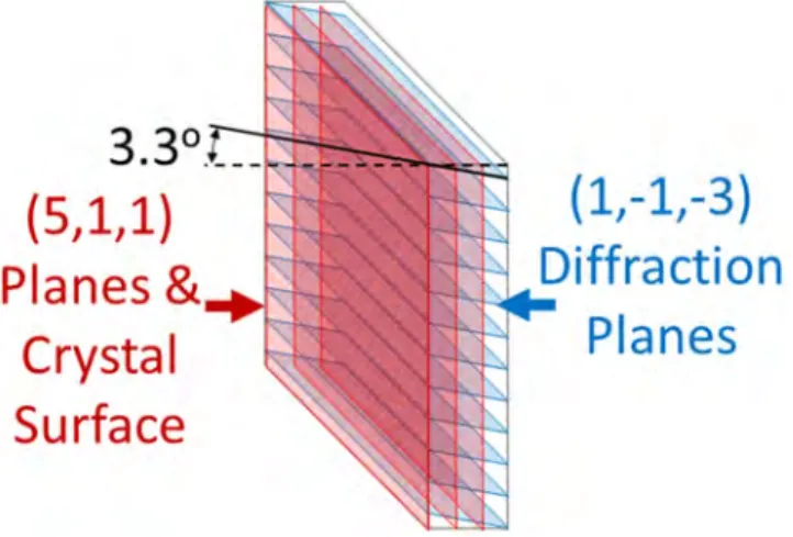
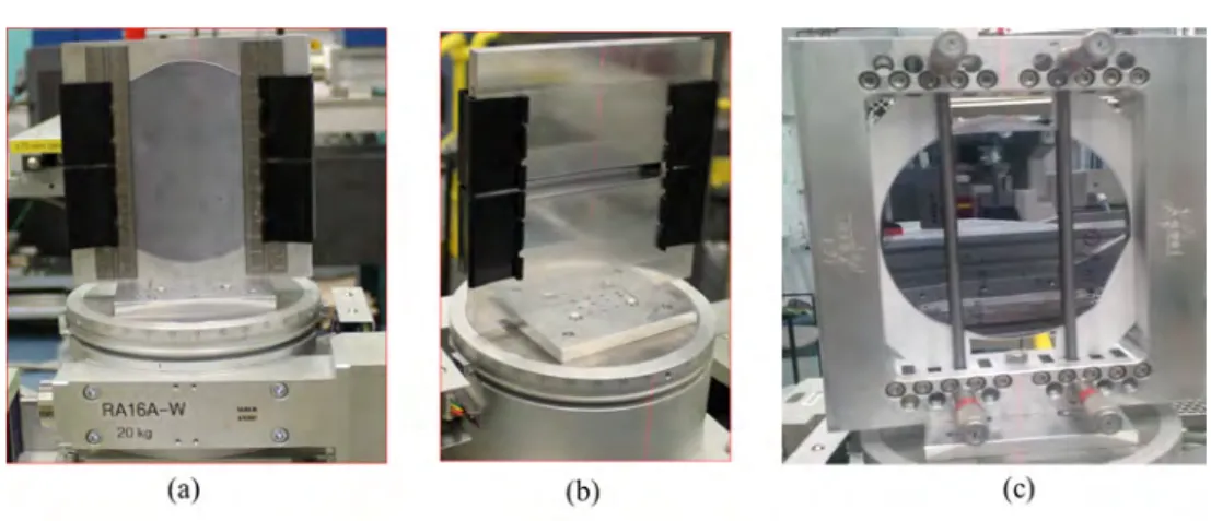
Flat or bent crystals have been widely used as x-ray optical elements for diffraction of x-rays, and can be used either in the reflection (Bragg crystal) or transmission (Laue crystal) geom-etry. The MEI system is made up of a cylindrically bent Laue single silicon (Si) crystal (wafer) monochromator, scanning and positioning stages for the subjects, a 100 µm pixel size flat panel detector, and a data acquisition and control system. For the diffraction of x-rays with a bent Laue crystal, the two possible geometries that can be used are focusing and non-focusing (Cauchois) geometries (Ren et al 1997). In the focusing geometry, the convex side of the bent crystal faces the x-ray source whereas in the non-focusing geometry, the concave side faces the source. The MEI system bent Laue monochromator is used in the focusing geometry. The thickness of the bent Si crystal (5,1,1) is 750 microns and for the diffraction of synchrotron x-rays, the (3,1,1) type diffraction (reflection) plane having an asymmetry angle of 3.3° is used. The asymmetry angle is measured in the diffraction plane between the crystal surface normal and the diffraction planes. In a crystal, the atoms are arranged in a periodic manner forming atomic planes, also referred to as crystal or lattice planes. The descriptions of these planes and their directions are done using three integers termed Miller indices, (hkl) and [hkl] for planes and directions, respectively. Figure 1 is an illustration showing the orientation of the crystal and lattice planes used for the MEI system. It should be noted that in figure 1, the planes are not bent. We have used comas to separate the integers and ‘minus sign’ instead of a ‘bar’ on the integers for clarity. Bending of the crystal was achieved by means of a frame bender. That is, by mounting the crystal onto an aluminium frame machined to the required bending radius of 1 m (figures 2(a) and (b)). An aluminum frame was used because of its good thermal conductivity, light weight, ease of machinability and low cost. At the early stage of the MEI system development, a four-bar bender (figure 2(c)) and (1,1,1) type reflection
Figure 1. An illustration showing the orientation of the crystal and lattice planes used
for the MEI system. The crystal surface is parallel to the (5,1,1) planes. The planes used for diffraction through the crystal are the (1,−1,−3) which are inclined 3.3° relative to the surface as shown. The planes in the figure are not bent for clarity.
3.3°
(5,1,1)
Planes &
Crystal
Surface
(1,-1,-3)
Diffraction
~
-
PI an es
having 19.5° asymmetry angle from a Si (5,1,1) crystal wafer of thickness 600 µm, were used. The (3,1,1) type reflection from a Si (5,1,1) crystal wafer of 750 µm thickness was opted for because of its excellent energy dispersive properties for Spectral K-edge subtracting imag-ing (Zhu et al 2014). The four-bar bender allowed for the variation of the crystal’s bending radius. Other methods of bending a crystal include the use of a leaf-spring bender (Ko et al 2014), superficial indentations (Barriere et al 2010, Bellucci et al 2011), mixed crystals with a composition gradient, and application of a thermal gradient (Smither et al 2005). Generally, bent crystals increase the angular and energy acceptance of the incident x-rays compared to flat crystals, and hence an increase in the x-ray flux available for usage (Sutter et al 2008). The bending of the crystal causes a change in the angle and d-spacing of the lattice planes as the beam traverses the crystal, which results in an increment in the energy bandwidth. The enhancement of the energy bandwidth due to bending is approximately 100 times the unbent values (Erola et al 1990). Also the reflectivity and diffraction efficiency of bent crystals can be close to 100% (Bellucci et al 2013). An extensive study of bent crystal x-ray optics for a Laue monochromator can be found in the literature (Suortti 1988, Schulze and Chapman 1995, Ren et al 1999). The flat pane detector (FPD), an EID, associated with the MEI system is C9252DK-14 (Hamamatsu Photonics K. K., Japan). This detector is used in some clinical dental x-ray machines (Hall et al 2013).
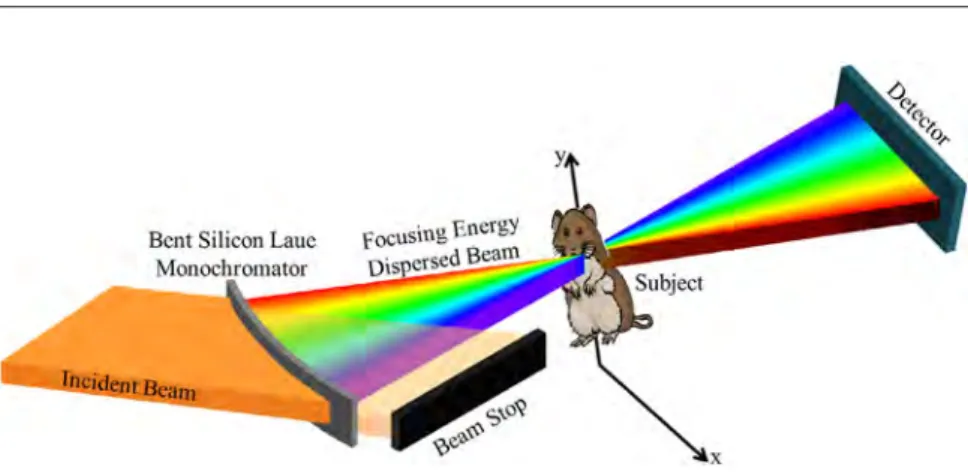
A horizontally focused polychromatic x-ray beam from a filtered synchrotron white beam is prepared by the MEI system. The energy range of the filtered white beam used is 20–50 keV, which matches the lower end of the diagnostic imaging range accessible by the BMIT-BM. Filtering of the white beam is done using a 0.1 mm thick aluminum (one of the BMIT-BM filters) and 105 mm thick water filter. Water, a low atomic number material, was used as a fil-ter to evenly attenuate the large energy range spectrum since the attenuation is dominated by Compton scattering, which is largely energy independent. Though the water filter does scatter the white beam, this has no negative effect on the MEI system because it was located upstream of the MEI system (~5 m) in the BM hutch. The focused beam on passing through a subject placed at the focus then diverges onto the FPD where the energy range collected is spatially dispersed. At the subject location where the beam focuses, the beam has a horizontal width along x and the range of angles through the focus (angles around the x direction) represents a range of x-ray energies. At the detector location downstream, the range of angles spatially disperses the x-rays as a function of energy across the vertical dimension of the detector.
Figure 2. Methods employed in bending the Si crystal wafer: (a) frame bender—view
from upstream; (b) frame bender—view from downstream and; (c) four-bar bender. The Si crystal wafer is also shown in (a) and (c).
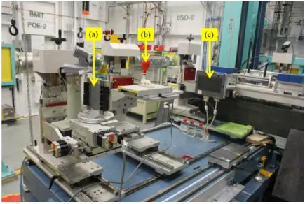
The horizontal or x dimension is preserved from the object location. To create an image of a subject, the subject is scanned horizontally through the focused beam, creating a two spatial dimensional image: height ( y )—vertical beam size; width (x)—horizontal scan length; and a third axis representing the transmission through the object at the x-y location as a function of energy, which can be as large as 15 keV. Thus, each x−y pixel in the detector represents the x-ray transmission through the subject at a horizontal location (x) and the vertical location ( y ), the transmission through the subject at an energy. A schematic representation of the MEI system is shown in figure 3, and its experimental setup shown in figure 4.
2.2. Focal properties study
Measurements of focus size of the focused beam prepared by the bent crystal were carried out in two ways and for various beam sizes incident on the bent Laue crystal monochromator. One set of measurements involved scanning a knife edge horizontally through the focused beam at various distances near the focal point to establish its location. For the second set of measurements, a 13 µm pixel size detector, Hamamatsu AA-60 x-ray converter coupled to a C9300-124 camera (Hamamatsu Photonics K. K., Japan), was used to directly image the beam near the focal region. The C9252DK-14 (Hamamatsu Photonics K. K., Japan) FPD which constitute a part of the MEI system could not be used for this study because of its susceptibility to radiation damage. In the AA-60 x-ray converter, the lens and charge-coupled device are out of the x-ray beam and thus radiation damage is not a problem. The focal prop-erties obviously depend on the bend radius which is fixed, but also on the Laue diffraction conditions-specifically the reflection plane used, x-ray energy and asymmetry angle. With a focusing bent Laue geometry, there are two foci, the polychromatic and geometric. These foci do not generally coincide, resulting in what is termed ‘crystal depth broadening’ or focus broadening (Suortti and Schulze 1995). The focus broadening is considered as the main limitation of the Laue geometry for achieving a small focus size (Mocella et al 2004). It has been established that focus broadening can be reduced, that is the two foci can be made to be as close as possible to each other, by an appropriate choice of the crystal asymmetry angle, thickness, and bending radius (Schulze et al 1998, Mocella et al 2004, Nesterets and Wilkins 2008). It follows then that the smallest possible focus size can only be achieved when the two foci coincide.
Figure 3. Schematic representation of the MEI system. The frame bender used for
2.3. Photon and dose rates
To measure the photon rate made available by the MEI system for imaging of subjects, an air filled ionization chamber (IC Plus 150, FMB Oxford Ltd, Oxford, UK) was used. The ioniz-ation chamber was placed at the photon beam focal point, and measurements made for differ-ent horizontal beam widths inciddiffer-ent on the bdiffer-ent crystal Laue monochromator. The relationship between the ionization chamber current (ich) measured and the photon rate (N˙o) is given by equation (1) ρ = µ ρ ε N i q E L ˙o ch ei e ph ch ch EA (1) where εei is the average energy required to produce an electron–ion pair in air (33.4 eV), qe is the charge of an electron, Eph is the photon’s energy, ρch is the density of air, Lch is the ioniz-ation chamber’s length, µ
ρEA is the energy absorption mass attenuation coefficient of air. For
any medical or biomedical imaging system, the dose delivered to subjects imaged using such a system is considered a serious issue (Anderson et al 2010, Mittone et al 2013). With the measured photon rate using the ionization chamber, surface dose rate, D˙s to a subject imaged was estimated using equation (2)
D N E A ˙s= ˙o ph EA. µ ρ (2) In equation (2), A is the area of the beam at the point measurement is made and ρµ
EA is the
energy absorption mass attenuation coefficient of tissue. During the photon rate measure-ments, pieces of GafChromic RTQA2 film (ISP Technologies Inc., NJ, USA) were exposed to the x-rays by placing them at the entrance window of the ionization chamber. The area of the beam (A) in equation (2) was obtained from the exposed GafChromic films.
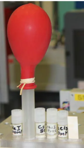
Figure 4. Experimental setup of the MEI system: (a) Si crystal wafer mounted on a
frame bender, (b) subject to be imaged placed at the position the beam focuses and, (c) Hamamatsu flat panel detector.
tem. If the various elements that the K-edges have been covered are used as contrast agents in subjects, one may like to know the minimum detectable levels of concentrations of these elements by the imaging system. To study this, subjects constituting different concentrations (0.5, 1.0, 5.0 and 10.0 mg ml−1) of sodium iodide (NaI), cesium chloride (CsCl), and barium chloride (BaCl2) solutions, were imaged. The concentrations in units of mM are: 3.3, 6.7, 33.4, and 66.7 mM for NaI; 3.0, 5.9, 29.7, and 59.4 mM for CsCl; 2.4, 4.8, 24.0, and 48.0 mM for BaCl2. The choice of these concentrations was based on what have been used in the litera-ture (Arfelli 2000, Roessl et al 2010, Wang et al 2011a, Zbijewski et al 2014). The solutions were contained in 50 ml centrifuge tubes having an external diameter of 11.5 mm (Corning Incorporated, Corning, NY, USA). For the MEI system’s energy resolution, the Gaussian widths (σ) of the absorption edges of iodine (I) and barium (Ba) were measured, and the corre sponding full-width-half-maximum (FWHM) calculated based on equation (3) (Roessl and Herrmann 2009)
FWHM=2σ In4=2σ 2In2 .
(3)
2.5. Material decomposition algorithm
It is well known that x-rays are attenuated by matter. The attenuation can be described by physical interactions between the x-rays and matter or analytically as a linear combina-tion of basis funccombina-tions representing a colleccombina-tion of absorbing materials (Schirra et al 2014). Photoelectric effect, Compton scattering and discontinuity at a K-edge are the three basis functions that can be used (Taguchi and Iwanczyk 2013, Schirra et al 2014). The discontinu-ity at a K-edge is only used if a material has a K-edge in the energy range of interest (Wang et al 2011b). It should be noted that in the diagnostic energy range, photoelectric absorption and Compton scattering are the two principal means materials attenuate x-ray and hence the two basis functions commonly used (Schirra et al 2014). The energy range of x-rays we have used (20–50 keV) falls within the diagnostic energy range. Material decomposition algorithms enable material-specific information such as mass density and effective atomic number to be obtained, and also the quantification of material concentration (Mccollough et al 2015). With an accurate material decomposition algorithm, the spatial distribution of basis functions can be quantified on a pixel basis (Taguchi and Iwanczyk 2013). Because of the interest in contrast elements with K-edges in the diagnostic energy range, the algorithm we have used to extract concentration information is based on a least squares fit to known absorption values for the contrast elements and tissues such as bone and water. Our approach is similar to that of oth-ers (Kozul et al 1999, Rebuffel and Dinten 2007, Firsching et al 2011), and is described as follows.
For a subject, if the photon counts for incident, N0, and transmitted, N, beam are measured at some energies, Ei ⩽ i ⩽ n, then N(Ei) and N0(Ei) can be normalized to form:
= − ( ) ( ) ⎛ ⎝⎜ ⎞ ⎠⎟ R N E N E ln . i i i 0 (4) Based on Lambert–Beer’s law, equation (4) can be related to the expected attenuation of the object by m materials for 1 ⩽ j ⩽ m and 1 ⩽ i ⩽ n as
ri E t t, where the index refers to .i E j m j i j j j m ij j j i 1 1
∑
µ∑
ρ ρ µ ρ ρ = = = = ( ) (5) That is,∑
µ ρ ρ = − = = ( ) ( ) ⎛ ⎝⎜ ⎞ ⎠⎟ r N E N E t ln . i i i j m ij j j 0 1 (6) Equation (6) is linear and its matrix form is⎡ ⎣ ⎢ ⎢ ⎢ ⎢ ⎤ ⎦ ⎥ ⎥ ⎥ ⎥ ⎡ ⎣ ⎢ ⎢ ⎢ ⎢ ⎢ ⎢ ⎢ ⎢ ⎢ ⎢ ⎛ ⎝⎜ ⎞ ⎠⎟ ⎛ ⎝⎜ ⎞ ⎠⎟ ⎛ ⎝⎜ ⎞ ⎠⎟ ⎤ ⎦ ⎥ ⎥ ⎥ ⎥ ⎥ ⎥ ⎥ ⎥ ⎥ ⎥ ⎡ ⎣ ⎢ ⎢ ⎢ ⎢ ⎢ ⎢ ⎢ ⎢ ⎢ ⎤ ⎦ ⎥ ⎥ ⎥ ⎥ ⎥ ⎥ ⎥ ⎥ ⎥ r r r N N N N N N t t t t t t t t t . . . . ln . . ln . . ln .. . . . . . . .. . . . . . . .. . . i n i i n n j j j m m m i ji j j mi m m n jn j j mn m m 1 1 01 0 0 11 1 1 1 1 1 1 1 1 1 1 µ ρ ρ µ ρ ρ µ ρ ρ µ ρ ρ µ ρ ρ µ ρ ρ µ ρ ρ µ ρ ρ µ ρ ρ = − − − = + + + + + + + + + + + + µ ρ µ ρ µ ρ µ ρ µ ρ µ ρ µ ρ µ ρ µ ρ ρ ρ ρ = + + + + + + + + + + + + = ⎡ ⎣ ⎢ ⎢ ⎢ ⎢ ⎤ ⎦ ⎥ ⎥ ⎥ ⎥ ⎡ ⎣ ⎢ ⎢ ⎢ ⎢ ⎢ ⎢ ⎢ ⎢ ⎢ ⎤ ⎦ ⎥ ⎥ ⎥ ⎥ ⎥ ⎥ ⎥ ⎥ ⎥ ⎡ ⎣ ⎢ ⎢ ⎢ ⎢ ⎢ ⎤ ⎦ ⎥ ⎥ ⎥ ⎥ ⎥ r r r t t t . . . . .. . . . . . . .. . . . . . . .. . . . . . . i n j m i ji mi n jn mn j j m m 1 11 1 1 1 1 1 1 (7)
Equation (7) is an n × m matrix, where ri (1 ⩽ i ⩽ n) are the measurements made and ρ tj j (1 ⩽ j ⩽ m) are the materials projected concentrations to be solved for. The following condi-tions are said to be applicable to equacondi-tions of this type (Kozul et al 1999, Dong-Goo et al 2009): for n = m, ρ tj j can be determined; for n < m, ρ tj j cannot be determined and; for n > m, ρ tj j are overdetermined. In our case, n > m and approximate values of ρ tj j were determined by method of linear least squares (LLSQ) (Kozul et al 1999).
3. Results and discussion
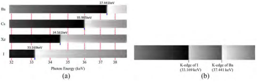
In our preliminary results (Bassey et al 2015), four materials (I, Ba, bone and water) were successfully decomposed in terms of their projected concentrations. This was achieved using the (1,1,1) type reflection, a 0.9 mm focused beam (12 keV energy range), and a 108 cm Si crystal bend radius; Si crystal was bent with a four-bar bender. Since the K-edges of xenon (Xe) and cesium (Cs) were also covered in the energy range of the focused beam, Xe and Cs were included as part of the subjects imaged in subsequent experiments. With Xe and Cs included, the number of materials imaged and decomposed became six. The images of the focused beam showing K-edges of all the elements covered are shown in figure 5(a). Figure 5(b) shows the segmentation of I and Ba K-edges from a mixture of NaI and BaCl2
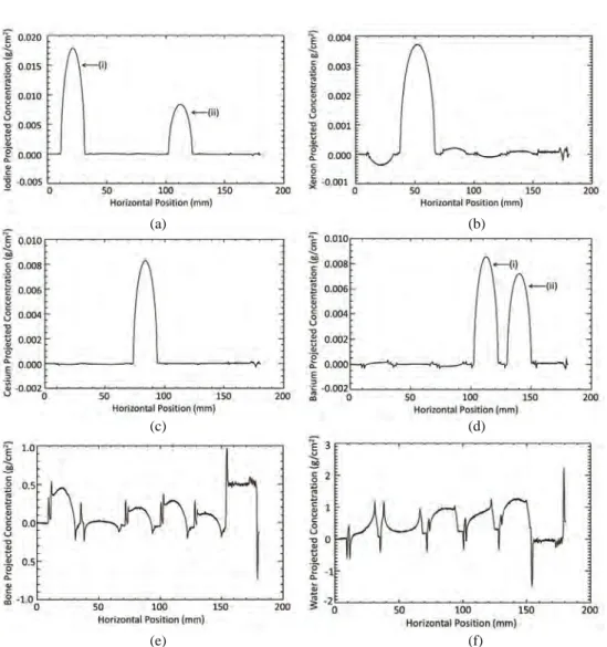
solutions. For figure 5(b), the beam size was 50 mm (horizontal) by 6 mm (vertical), energy range of focused beam was 15.0 keV, the FWHM of the iodine and barium K-edges were 46.2 eV and 62.2 eV, respectively. Shown in figure 6 is the subject imaged constituting of six materials: NaI solution (15.0 mg ml−1 or 100 mM); Xe gas (99.999% pure from Praxair Inc. USA); CsCl solution (8.4 mg ml−1 or 50 mM); a mixture of NaI and BaCl2 solutions (15 mg ml−1 and 20.8 mg ml−1 or 100 mM each); BaCl2 solution (10.4 mg ml−1 or 50 mM); and ‘physics bone’-simulated bone (hydroxyapatite in a plastic matrix). For imaging of the sub-ject shown in figure 6, the horizontal scan length was 180 mm at 0.1 mm step, beam dimen-sion incident on the bent Si crystal Laue monochromator was 25 mm (horizontal) by 6 mm (vertical), and energy range of focused beam was 6.9 keV. Using the material decomposition algorithm, these six materials were decomposed in terms of their projected concentrations, and are as shown in figure 7. With reference to figures 6, 7(a) and (d) the position sensitivity of the flat panel detector used is clearly demonstrated.
Geometrically, with the Si crystal wafer bent to a radius of 1 m, the expected focal point should be at approximately 0.5 m from the Si crystal. But due to the fact that geometric and polychromatic foci do not generally match over the energy range of the experiment, a point or source size limited focus cannot be achieved, and at the expected focal point. By scan-ning the region close to the expected focal point using the 13 µm pixel size Hamamatsu AA-60 detector enables the smallest possible focal size, and its position from the Si crystal to be determined. Figure 8 shows the results of the scans around the focal region, for dif-ferent beam sizes incident on the bent Si crystal, using the 13 µm pixel size detector. From figure 8, the 0 mm position along the beam (vertical axis) is the expected geometric focal point, 0.5 m from the crystal while the scan was performed from the −30 mm position (upstream) to the +30 mm position (downstream). Based on the scans, the smallest focal size achieved was 0.2 mm, and was between −1 mm and 4 mm from the 0 mm position. For the focus size measurements by scanning a knife edge horizontally through the beam, the smallest focus size measured was 0.3 mm. The image for each of the beam dimensions shown in figure 8 was created from a number of images taken of the beam as the 13 µm pixel size Hamamatsu AA-60 detector translated along the beam path. Efforts were made to get the trajectory of the detector to match the overall path of the beam, but there was some residual error which resulted in a slight inclination of the beam relative to the x-y axes (~0.7°). This explains why the images in figure 8 are lined diagonally.
Table 1 shows the photon rates available for imaging subjects and the estimated surface dose rates to a subject when imaged using the MEI system. For the same photon rates meas-urement experimental setup but a flat instead of a bent crystal used, the photon rate for a
Figure 5. (a) Images of the focused beam showing K-edges of all the elements covered,
and (b) segmentation of iodine and barium K-edges from a mixture of NaI and BaCl2 solutions.
Xe
34 35 36 Pho-on Energy (keV)
50.0 mm (H ) × 6.0 mm (V ) beam size incident on the flat crystal was 5.98 × 10⁶ ph s−1. From table 1, for a bent crystal and for the same beam size of 50.0 mm (H ) × 6.0 mm (V ), the photon rate is 103 order of magnitude higher than that of a flat crystal. Given surface dose rate (D˙s), the cumulative surface dose Ds can be computed using
=D D h v
˙
s s
(8) where v is the scan step of subject per exposure time and h is the width of the beam at focus (horizontal beam size) because the subject was scanned horizontally. For imaging of the sub-ject shown in figure 6, the beam size, scan step, and image acquisition time (exposure time) for each scan step were 25 mm (H ) by 6 mm (V ), 0.1 mm, and 6.66 ms, respectively. By using the corresponding D˙s for a 25 mm (H ) by 6 mm (V ) beam size from table 1, and noting that h is 5 mm, the computed cumulative dose (Ds) to the subject was 2.90 mGy. This dose estimate assumes that there is no time delay between images being acquired by the imaging system and each image was acquired in 6.66 ms intervals. The actual acquisition time between images was approximately 3 s, which greatly increased the dose to the subject (~1.3 Gy).
Figure 6. Subject imaged constituting of six materials: starting from left to right: NaI,
Xe, CsCl, a mixture of BaCl2 and NaI, BaCl2, and ‘physics bone’—simulated bone (hydroxyapatite in a plastic matrix).
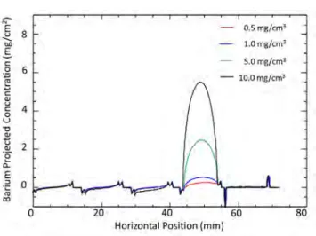
Results of the MEI system sensitivity study are shown in figures 9–11 for iodine, cesium, and barium, respectively. The beam size incident on the bent Laue Si crystal monochromator was 25 mm (H ) by 6 mm (V ) while the focused beam had a minimum energy of 31.57 keV and a maximum energy of 40.09 keV (i.e. an energy range of 8.52 keV). This energy range covers the K-edges of iodine, xenon, cesium, and barium. The essence of the sensitivity study was to determine the detectability limits of these elements (excluding xenon) in terms of their concentrations. From figures 9–11, and as would be expected, the sensitivity of the MEI sys-tem increases with increase in concentration of the solutions imaged. The sensitivity of the MEI system to the detection of cesium is higher compared to iodine and barium. From the results, the minimum level of concentration that the MEI system can detect is 0.5 mg ml−1 for cesium, and 1.0 mg ml−1 for iodine and barium. The stated detectable limits were established visually based on the projected concentration plots (figures 9–11). Since the flat panel detector
(a) (b)
(c) (d)
(e) (f)
Figure 7. Projected concentration (g cm−2) of six materials decomposed: (a) iodine
from (i) NaI solution, (ii) a mixture of BaCl2 and NaI solutions, (b) xenon, (c) cesium, (d) barium from (i) BaCl2 solution, (ii) a mixture of BaCl2 and NaI solutions, (e) bone, (f ) water. The subject imaged constituting of the six materials is shown in figure 6.
w
c 0.010 ~ 0 u ~ o_oos ~ "f_ 0.000 ., C ] -O.OOS '"o----5~0----1~00---150'---:'200Horiiontal Posit on (mm)
l
0.010~---- - - ~ - - - - ~ - - - ~ ~ 5 0.008 -~ c 0.006 8 cc ,3 0.004 .,,..
g o.002~ o' ~ 0.000 ,_ _ _ _ _ _ _ .i!:a
-0.0020 50 100 150Ho~10ntal Position (mm)
200 ~
~
0 u .,, ti!
.,_ C 0 0,002 0.001 0,000 g •010Cll ~----".----,~---,,~-~-".CC ~ o ~ m m ~Horizontal Position (mm)
§
0.0 1 0 , - - - ~ - -- ~ - - - . - - - ---, -;. .; o.oos 0s
!
8 .,, ti ·...
~ E :, -111 +-(II)!
-0.oo20'---s""'o ____ 1_00~ - ~ - -,. ... so _ _ _ _ 2__.oo Hortzon!ill Position (mm)13.---~----
-.-
----~---,
~ ..2!! § 2 "' g C ~ 8 "O 0 t!..
!
-t ~ .! 50 100 150 200 ~ -20 _ _ _ _ _ 50 _ _ _ _ 100 _ _ _ _ 15_0 _ _ _ _ 200associated with the MEI system is position sensitive, visual comparisons of the projected concentrations of each element, at each concentration level, to the background were made. In terms of the energy resolution, FWHM at iodine K-edge (33.17 keV) was 48.8 eV and that at barium K-edge (37.44 keV), 36.9 eV. The energy bandwidth of iodine and barium was found from a derivative of the measured edge data for iodine and barium. A Gaussian fit to the edge derivatives for iodine and barium was done, which resulted in a measure of the width of the edges. For other energies, the estimated energy blurring (Gaussian width or FWHM) was found by a linear interpolation from those measured at iodine and barium K-edges. Based on the linear interpolation, FWHM at cesium K-edge (35.99 keV) was 41.0 eV.
The arc-tangent features-spikes and slow/gradient background variations that are pronounced in figures 7(e) and (f ), 9 and 11 are crossover artifacts similar to that which occur with the normal
Figure 8. Results of scans about the focal point 13 µm pixel size Hamamatsu AA-60
detector. Vertical beam size incident on the bent Laue Si crystal monochromator was 6 mm while the horizontal beam size was varied: (a) 5 mm, (b) 10 mm, (c) 20 mm, (d) 25 mm, and (e) 30 mm.
Table 1. Results of photon rate measurements and estimated surface dose rates.
Beam size incident on bent crystal H × V (mm2) Storage ring current, Ri (mA) Ionization chamber current, ich (pA) ich (pA) at a Ri of 200 mA Beam size at focus H × V (mm2) Area of beam at focus, A (cm2) Photon rate (ph s−1) at focus per 200 mA of Ri Surface dose rate (mGy s−1) at focus per 200 mA of Ri 25.0 × 3.0 177.9 950.0 1068.0 5.0 × 3.0 0.16 1.09 × 10⁹ 11.8 25.0 × 6.0 177.8 1315.0 1479.2 5.0 × 6.0 0.30 1.50 × 10⁹ 8.7 50.0 × 3.0 177.6 3580.0 4031.5 9.5 × 3.0 0.29 4.10 × 10⁹ 24.5 50.0 × 6.0 177.8 4800.0 5399.3 9.5 × 6.0 0.57 5.49 × 10⁹ 16.7 20
I
10 E"'
.,
co g,n 0 0 co.g
"§ -10 0.. -20 (a) 0.0 Position across Beam (mm) (b) 0.5 0.0 0.5 Po ition aero s Beam (mm) (c) 0.5 0.0 0.5 Position across Beam (111111) (d) 0.5 0.0 0.5 Position across Beam (mm) (e) 0.5 0.0 0.5 Po ition acros · IJcam (mm)two-beam K-edge subtracting (KES) and Spectral KES imaging (Zhu et al 2014). It is not so obvious with the MEI system what the artifact comes from. But with two-beam KES, when one beam is eclipsed due to a high absorbing object before the other one is, then the analysis method interprets this as either the presence of the contrast material (if the above edge beam is absorbed more than the below edge beam) or the ‘negative’ contrast mat erial (if the below is absorbed more than the above). The arc-tangent feature occurs because as the subject traverses the beam it begins by blocking one part of the beam before blocking it all, for example, the low energy part of the beam first before the high energy part, resulting in a negative projected contrast value. When the object leaves the beam the opposite occurs resulting in a positive contrast value. The shape of the subject defines the shape of the artifact and because the data is from circular tubes it appears to be a derivative of the tube or the arc-tangent. The term crossover artifact is used because it occurs when the subject is upstream or downstream of the beam’s focus.
Figure 9. Projected concentrations (mg cm−2) of iodine for different concentrations
(mg cm−3) of NaI solution imaged.
Figure 10. Projected concentrations (mg cm−2) of cesium for different concentrations
(mg cm−3) of CsCl solution imaged.
--
E.
5.0 mg/cm' C: ,Q 6E
10.0 mg/cm' ,._. C: IIJ u 4 C: 0 u "CJ ;I! u 2 IIJ·
e-c.. IIJ C 0 'o .2. 0 20 40 60 80Horizontal Position (mm)
"' E 0.5 mg/cm' 8 u
--
OD 1.0 mg/cm'E.
5.0 mg/cm' C: 0 6 ·.;::; - 10.0 mg/cm' [" i: C1J u 4 C: 0 u -a C1J ti 2 C1J·
e
Q_ E ::, 0 ·:a u 0 20 40 60 80Chemical concentrations, amount of materials, pixel intensities, frequency counts, and emission spectra are some examples of quantities or variables that going by physical prin-ciples, can never have negative values (Bro and Jong 1997, Van Benthem and Keenan 2004, Chen and Plemmons 2010). Problems in which these types of variables are to be solved for usually involve solving overdetermined linear systems (more equations are given than unknowns), and are termed linear least squares problems (Gander et al 2014). The decomposi-tion of materials in terms of their projected concentradecomposi-tions shown in figures 7, 9–11 required solving an overdetermined linear system using a LLSQ algorithm written in IDL (Interactive Data Language, ITT Exelis Visual Information Solutions, Boulder, CO, USA). When solving linear least squares problems for quantities than can only take on non-negative values, if the measured data used is corrupted by noise, the quantities can take on negative values, which are physically meaningless (Chen and Plemmons 2010, Luo and Duraiswami 2011). To ensure non-negative values, non-negative least squares (NNLS) methods or non-negative constrained least squares methods are used (Bro and Jong 1997, Heinz and Chein 2001, Ham and Butler 2007, Désesquelles et al 2009, Luo and Duraiswami 2011). Generally, from the projected concentration values shown in figures 7 and 9–11, it will be agreed that there is no need to use a NNLS based algorithm for the materials decomposition, as these values are non-negative. But in the near future, there is plan to develop a NNLS algorithm using the IMSL_LINLSQ routine in IDL for materials decomposition.
4. Summary and conclusions
A novel single bent Laue Si (5,1,1) crystal monochromator based MEI system has been devel-oped for biomedical imaging application at the BMIT bend magnet beamline, Canadian Light Source. The energy bandwidth of the horizontally focused beam prepared by the MEI system varies: 15.0 keV for a 50 mm (horizontal) by 6 mm (vertical) beam size; and 6.9 keV for a 25 mm (Horizontal) by 6 mm (vertical) beam size. These energy bandwidths cover the K-edges of iodine, xenon, cesium, and barium, thus enabling the simultaneous use of these energies for imaging. The large beam width of the BMIT bending magnet beamline is in part what allows the large spectral energy to be covered. With the MEI system, segmentation (decomposition)
Figure 11. Projected concentrations (mg cm−2) of barium for different concentrations
of BaCl2 solution imaged.
1
8 0,5 mg/cm' u ----00 1,0 mg/cm• E C: 5.0 mg/cm• 0 6 ·.;::: 10.0 mg/cm1 ~ C:.,
u 4 C: 0 u '0.,
~ 2 OJ·e
0.. E :, 0 ·c "' <O 60 80 Horizontal Position (mm)ml−1 for iodine and barium, and 0.5 mg ml−1 for cesium. The detection limit of 1.0 mg ml−1 for iodine is comparable to 1.3 mg ml−1 reported for Spectral KES imaging system (Zhu et al 2014). In joint arthrography, the concentration of iodine used as contrast agent is said to be relatively high—15–80 mg ml−1 upon dilution in the synovial fluid (Zbijewski et al 2014). In the study by Schültke et al (2010), it is stated that after administering 0.9 ml kg−1 iodinated contrast agent (Xenetix®) to a pig model via intravenous injection, the peak iodine concentration in the internal carotid and middle cerebral arteries reached 35 mg ml−1. Also, in a lung cancer and angiogenesis imaging using synchrotron radiation (Xiaoxia et al 2010), the concentration of barium contrast agent (BaSO4 suspension) injected to a mouse was 500 mg ml−1. These stated concentrations of iodine and barium contrast agents in biological subjects are very high when compared to the minimum detection limits of iodine and barium for the MEI system. Thus, the sensitivity of the MEI system may be sufficient for K-edge and multi-ple K-edge imaging (projection not CT mode) applications in which these elements, including xenon, are used as contrast agents. The large energy range that can be covered raises the possi-bility of using the MEI system in a vertical diffraction plane where the imaging energy can be changed rapidly by a simple vertical motion of the monochromator to different K-edges. This motion would need to be coupled with motions of the object and detector, but the simplicity of the system might warrant its use in this way. The developed MEI system adds to the various imaging modalities available at BMIT.
Acknowledgments
We acknowledge the support from the National Sciences and Engineering Research Council of Canada (NSERC), the Social Sciences and Humanities Research Council of Canada, the Canadian Institute of Health Research Training grant in Health Research Using Synchrotron Techniques (CIHR-THRUST), the University of Saskatchewan, and the Akwa Ibom State University. BB, MM, NS, PQ are Fellows, and DC a mentor, in CHIR-THRUST. Research described in this paper was performed at the CLS, which is funded by the Canada Foundation for Innovation, the NSERC, the National Research Council Canada, the CIHR, the Govern-ment of Saskatchewan, Western Economic Diversification Canada, and the University of Sas-katchewan. CK is thankful to the Institute of Accelerator Technologies (Ankara University) and Turkish State Planning Organization (DPT) for support (Grant No: DPT2006K-120470).
References
Alvarez R E and Macovski A 1976 Energy-selective reconstructions in x-ray computerised tomography
Phys. Med. Biol.21 733–44
Alvarez R E, Seibert J A and Thompson S K 2004 Comparison of dual energy detector system performance Med. Phys. 31 556–65
Anderson N G et al 2010 Spectroscopic (multi-energy) CT distinguishes iodine and barium contrast material in MICE Eur. Radiol. 20 2126–34
Aran S, Besheli L D, Karcaaltincaba M, Gupta R, Flores E J and Abujudeh H H 2014a Applications of dual-energy CT in emergency radiology Am. J. Roentgenol. 202 W314–24
Aran S, Shaqdan K and Abujudeh H 2014b Dual-energy computed tomography (DECT) in emergency radiology: basic principles, techniques, and limitations Emerg. Radiol. 21 391–405
Arfelli F 2000 Synchrotron light and imaging systems for medical radiology Nucl. Instrum. Methods
Ballabriga R, Campbell M, Heijne E H M, Llopart X and Tlustos L 2007 The Medipix3 prototype, a pixel readout chip working in single photon counting mode with improved spectrometric performance
IEEE Trans. Nucl. Sci.54 1824–9
Barriere N, Guidi V, Bellucci V, Camattari R, Buslaps T, Rousselle J, Roudil G, Arnaud F-X, Bastie P and Natalucci L 2010 High diffraction efficiency at hard x-ray energy in a silicon crystal bent by indentation J. Appl. Cryst. 43 1519–21
Bassey B, Mercedes M, Samadi N, Belev G, Karanfil C and Chapman D 2015 Multiple energy synchrotron biomedical imaging system-preliminary results Proc. of IFMBE vol 51 pp 248–51 Bellucci V, Camattari R, Guidi V, Neri I and Barriere N 2011 Self-standing bent silicon crystals for very
high efficiency Laue lens Exp. Astron. 31 45–58
Bellucci V, Camattari R, Guidi V and Neri I 2013 Calculation of diffraction efficiency for curved crystals with arbitrary curvature radius J. Appl. Cryst. 46 415–20
Bro R and Jong S D 1997 A fast non-negative-constrained least squares algorithm J. Chemometrics 11 393–401
Butler A P H, Anderson N G, Tipples R, Cook N, Watts R, Meyer J, Bell A J, Melzer T R and Butler P H 2008 Bio-medical x-ray imaging with spectroscopic pixel detectors Nucl. Instrum. Methods Phys.
Res. A 591 141–6
Chen D and Plemmons R J 2010 Nonnegativity constraints in numerical analysis The Birth of Numerical
Analysis ed A Bultheel and R Cools (Singapore: World Scientific)
Désesquelles P, Ha T M H, Korichi A, Blanc F L and Petrache C M 2009 NNLC:non-negative least chi-square minimization and application to HPGe detector J. Phys. G: Nucl. Part. Phys. 36 037001 Dilmanian F A et al 1997 Single-and dual-energy CT with monochromatic synchrotron x-rays Phys.
Med. Biol.42 371–87
Dix W R et al 1996 Intravenous coronary angiography with synchrotron radiation Phys. Scr. T61 51–6 Dong-Goo K, Younghun S, Sungsu K, Seongdeok L and Kim J D 2009 Multiple object decomposition
based on independent component analysis of multi-energy x-ray projections Proc. IEEE Image
Processing Conf. pp 4173–6
Elleaume H et al 2000 First human transvenous coronary angiography at the European synchrotron radiation facility Phys. Med. Biol. 45 L39–43
Erola E, Etelaniemi V, Suortti P, Pattison P and Thomlinson W 1990 X-ray reflectivity of bent perfect crystals in Bragg and Laue geometry J. Appl. Cryst. 23 35–42
Faby S, Kuchenbecker S, Sawall S, Simons D, Schlemmer H-P, Lell M and Kachelrieß M 2015 Performance of today’s dual energy CT and future multi energy CT in virtual non-contrast imaging and in iodine quantification: a simulation study Med. Phys 42 4349–66
Firsching M, Nachtrab F, Uhlmann N and Hanke R 2011 Multi-energy x-ray imaging as a quantitative method for materials characterization Adv. Mater. 23 2655–6
Fornaro J, Leschka S, Hibbeln D, Butler A, Anderson N, Pache G, Scheffel H, Wildermuth S, Alkadhi H and Stolzmann P 2011 Dual- and multi-energy CT: approach to functional imaging Insights
Imaging2 149–59
Gander W, Gander M and Kwok F 2014 Scientific Computing—An Introduction Using Maple and MATLAB (Berlin: Springer)
Ghadiri H, Ay M R, Shiran M B, Soltanian-Zadeh H and Zaidi H 2013 K-edge ratio method for identification of multiple nanoparticulate contrast agents by spectral CT imaging Br. J. Radiol. 86 20130308
Hall C, Hausermann D, Maksimenko A, Astolfo A, Siu K, Pearson J and Stevenson A 2013 Detectors for the imaging and medical beam line at the Australian synchrotron J. Inst. 8 C06011
Ham K and Butler L G 2007 Algorithms for three-dimensional chemical analysis via multi-energy synchrotron x-ray tomography Nucl. Instrum. Methods Phys. Res. B 262 117–27
Heinz D C and Chein I C 2001 Fully constrained least squares linear spectral mixture analysis method for material quantification in hyperspectral imagery IEEE Trans. Geosci. Remote Sens. 39 529–45 Illing G, Heuer J, Reime B, Lohmann M, Menk R H, Schildwächter L, Dix W R and Graeff W 1995
Double beam bent Laue monochromator for coronary angiography Rev. Sci. Instrum. 66 1379–81 Jiyang C, Wenxiang C, Liang L and Ge W 2013 Combination of current-integrating/photon-counting
detector modules for spectral CT Phys. Med. Biol. 58 7009–24
Ko J Y O, Benjamin B O, James J S, Alan K P, Aaron L, Peter R, Matthew P M and Joel D B 2014 Designing and commissioning of a prototype double Laue monochromator at CHESS J. Phys.:
Conf. Ser.493 012006
Kozul N, Davis G R, Anderson P and Elliott J C 1999 Elemental quantification using multiple-energy x-ray absorptiometry Meas. Sci. Technol. 10 252–9
energy discriminating detectors Med. Phys. 38 245–55
Lee J, Lee Y, Cho S and Lee B-C 2012 A dual-energy material decomposition method for high-energy x-ray cargo inspection J. Korean Phys. Soc. 61 821–4
Luo Y and Duraiswami R 2011 Efficient parallel nonnegative least squares on multicore architecture
SIAM J. Sci. Comput.33 2848–63
Martinson M, Samadi N, Belev G, Bassey B, Lewis R, Aulakh G and Chapman D 2014 Development of a bent Laue beam-expanding double-crystal monochromator for biomedical x-ray imaging
J. Synchrotron Radiat.21 479–83
Mccollough C H, Leng S, Yu L and Fletcher J G 2015 Dual- and multi-energy CT: principles, technical approaches, and clinical applications Radiology 276 637–53
Miller J C 2010 Multi-energy computed tomography—new opportunities in imaging the abdomen
Radiol. Rounds 8 1–5
Mittone A et al 2013 An efficient numerical tool for dose deposition prediction applied to synchrotron medical imaging and radiation therapy J. Synchrotron Radiat. 20 785–92
Mocella V, Guigay J P, Hrdy J, Ferrero C and Hoszowska J 2004 Bent crystals in Laue geometry: dynamical focusing of a polychromatic incident beam J. Appl. Cryst. 37 941–6
Nesterets Y I and Wilkins S W 2008 Evaluation of the focusing performance of bent Laue crystals using wave-optical theory J. Appl. Cryst. 41 237–48
Nik S J, Meyer J and Watts R 2011 Optimal material discrimination using spectral x-ray imaging Phys.
Med. Biol.56 5969–83
Nik S J, Thing R S, Watts R, Dale T, Currie B and Meyer J 2014 Monte Carlo validation of optimal material discrimination using spectral x-ray imaging J. Inst. 9 T08003
Polad M S 2012 Photon counting spectral CT: improved material decomposition with K-edge-filtered x-rays Phys. Med. Biol. 57 1595
Puong S, Iordache R, Bouchevreau X and Muller S 2009 Dual-energy contrast enhanced digital mammography: theoretical and experimental study of optimal monoenergetic beam parameters using synchrotron radiation Proc. SPIE 725872583U
Rebuffel V and Dinten J M 2007 Dual-energy x-ray imaging: benefits and limits Insight Non-Destr. Test.
Cond. Monit.49 589–94
Ren B, Dilmanian F A, Chapman L D, Ivanov I, Wu X Y, Zhong Z and Huang X 1999 A bent Laue–Laue monochromator for a synchrotron-based computed tomography system Nucl. Instrum. Methods
Phys. Res. A 428 528–50
Ren B, Dilmanian F A, Chapman L D, Wu X Y, Zhong Z, Ivanov I, Thomlinson W C and Huang X 1997 Beam-smiling in bent-Laue monochromators AIP Conf. Proc. 417106–16
Roder F L 1985 Principles, history, and status of dual-energy computerized tomographic explosives detection J. Test. Eval. 13 211–6
Roessl E and Herrmann C 2009 Cramér–Rao lower bound of basis image noise in multiple-energy x-ray imaging Phys. Med. Biol. 54 1307–18
Roessl E, Herrmann C, Kraft E and Proksa R 2011 A comparative study of a dual-energy-like imaging technique based on counting-integrating readout Med. Phys. 38 6416–28
Roessl E, Thran A, Martens G, Istel T, Proksa R and Schlomka J P 2010 Dual-energy x-ray imaging by simultaneous integration and campbelling readout Proc. IEEE Nuclear Science Symp. Conf. pp 2112–5
Schirra C O, Brendel B, Anastasio M A and Roessl E 2014 Spectral CT: a technology primer for contrast agent development Contrast Media Mol. Imaging 9 62–70
Schlomka J P et al 2008 Experimental feasibility of multi-energy photon-counting K-edge imaging in pre-clinical computed tomography Phys. Med. Biol. 53 4031–47
Schültke E et al 2010 Synchrotron-based intra-venous K-edge digital subtraction angiography in a pig model: a feasibility study Eur. J. Radiol. 73 677–81
Schulze C and Chapman D 1995 Pepo: a program for the calculation of the reflectivity of cylindrically bent Laue crystal monochromators Rev. Sci. Instrum. 66 2220–3
Schulze C, Lienert U, Hanfland M, Lorenzen M and Zontone F 1998 Microfocusing of hard x-rays with cylindrically bent crystal monochromators J. Synchrotron Radiat. 5 77–81
Shastri S D, Fezzaa K, Mashayekhi A, Lee W-K, Fernandez P B and Lee P L 2002 Cryogenically cooled bent double-Laue monochromator for high-energy undulator x-rays (50–200 keV) J. Synchrotron
Siewerdsen J H et al 2006 High-performance dual-energy imaging with a flat-panel detector: imaging physics from blackboard to benchtop to bedside Proc. SPIE 614261421E
Smither R, Saleem K A, Beno M, Kurtz C, Khounsary A and Abrosimov M 2005 Diffraction efficiency and diffraction bandwidth of thermal-gradient and composition-gradient crystals Rev. Sci. Instrum. 76 123107
Suortti P et al 2000 Fixed-exit monochromator for computed tomography with synchrotron radiation at energies 18–90 keV J. Synchrotron Radiat. 7 340–7
Suortti P and Schulze C 1995 Fixed-exit monochromators for high-energy synchrotron radiation
J. Synchrotron Radiat.2 6–12
Suortti P and Thomlinson W 1988 A bent Laue crystal monochromator for angiography at the NSLS
Nucl. Instrum. Methods Phys. Res. A 269 639–48
Suortti P, Thomlinson W, Chapman D, Gmur N, Siddons D P and Schulze C 1993 A single crystal bent Laue monochromator for coronary angiography Nucl. Instrum. Methods Phys. Res. A 336 304–9 Sutter J P, Connolley T, Drakopoulos M, Hill T P and Sharp D W 2008 Ray traces of an arbitrarily
deformed double-crystal Laue x-ray monochromator Proc. SPIE 707770771N
Taguchi K and Iwanczyk J S 2013 Vision 20/20: single photon counting x-ray detectors in medical imaging Med. Phys. 40 100901
Tanguay J, Yun S, Kim H K and Cunningham I A 2015 Detective quantum efficiency of photon-counting x-ray detectors Med. Phys. 42 491–509
Tschentscher T and Suortti P 1998 Experiments with very high energy synchrotron radiation
J. Synchrotron Radiat.5 286–92
Van Benthem M H and Keenan M R 2004 Fast algorithm for the solution of large-scale non-negativity-constrained least squares problems J. Chemometrics 18 441–50
Wang X, Meier D, Mikkelsen S, Maehlum G E, Wagenaar D J, Tsui B M W, Patt B E and Frey E C 2011a MicroCT with energy-resolved photon-counting detectors Phys. Med. Biol. 56 2791–816
Wang X, Meier D, Taguchi K, Wagenaar D J, Patt B E and Frey E C 2011b Material separation in x-ray CT with energy resolved photon-counting detectors Med. Phys. 38 1534–46
Warp R J and Dobbins J T 2003 Quantitative evaluation of noise reduction strategies in dual-energy imaging Med. Phys. 30 190–8
Wu X Y, Dilmanian F A, Chen Z, Ren B, Slatkin D N, Chapman D, Shleifer M, Staicu F A and Thomlinson W 1995 Multiple energy computed tomography (MECT) at the NSLS: status report
Rev. Sci. Instrum.66 1346–7
Xiaoxia L, Jun Z, Jianqi S, Xiang G, Tiqiao X, Ping L and Lisa X X 2010 Lung cancer and angiogenesis imaging using synchrotron radiation Phys. Med. Biol. 55 2399–409
Xu T, Ducote J L, Wong J T and Molloi S 2006 Feasibility of real time dual-energy imaging based on a flat panel detector for coronary artery calcium quantification Med. Phys. 33 1612–22
Yagi M et al 2013 Gemstone spectral imaging: determination of CT to ED conversion curves for radiotherapy treatment planning J. Appl. Clin. Med. Phys. 14 173–86
Zbijewski W, Gang G J, Xu J, Wang A S, Stayman J W, Taguchi K, Carrino J A and Siewerdsen J H 2014 Dual-energy cone-beam CT with a flat-panel detector: effect of reconstruction algorithm on material classification Med. Phys. 41 021908
Zhu Y, Samadi N, Martinson M, Bassey B, Wei Z, Belev G and Chapman D 2014 Spectral K-edge subtraction imaging Phys. Med. Biol. 59 2485–503