Contents lists available atScienceDirect
Composite Structures
journal homepage:www.elsevier.com/locate/compstruct
The e
ffects of stacking sequence on drilling machinability of filament wound
hybrid composite pipes: Part-2 damage analysis and surface quality
Lokman Gemi
a,⁎, Sezer Morkavuk
b, U
ğur Köklü
b,
Şakir Yazman
caMeram Vocational School, Necmettin Erbakan University, 42000 Konya, Turkey
bFaculty of Engineering, Department of Mechanical Engineering, Karamanoglu Mehmetbey University, 70100 Karaman, Turkey cIlgın Vocational School, Selçuk University, 42615 Konya, Turkey
A R T I C L E I N F O Keywords:
Hybrid composite pipes Composite tubes Delamination Damage analysis Drilling machinability Stacking sequence Surface quality A B S T R A C T
In thefirst part of this two-part study, filament wound hybrid composite pipes with various stacking sequences were manufactured and mechanical properties such as hardness, ring tensile strength, and burst strength were experimentally investigated. After determining mechanical properties, drilling tests were performed to research machinability characteristics. The second part of the study consists damage analysis and surface quality ex-amination including ring test damage analysis, push-out delex-amination analysis, borehole damage exex-amination and borehole surface quality. The experimental data suggested that cutting parameters, stacking sequence, and the use of back-up were impactful on the formation and propagation of various types of damages. Especially, the effect of stacking sequence was remarkable. A larger delamination area was formed in Glass-Glass-Carbon (GGC) sample after the ring tensile tests compared to Glass-Carbon-Glass (GCG) and Carbon-Glass-Glass (CGG) samples. In all cases, the utilization of back-up lead to decrease of delamination with 9–40% reduction in surface roughness. When the back-up is not used during drilling, an excessive push-out delamination occurred in all drilling tests. Moreover, CGG samples represented lower push out delamination. In addition, position of the hole depending on the winding angle plays a key role on damage formation and surface quality.
1. Introduction
Filament wound composite pipes (FWCPs) are used in various in-dustry such as petroleum, construction, and automotive due to their superior properties like high strength and resistance against chemical reactions, abrasion, and UV light[1–7]. Numerous studies have been carried out to investigate the effects of the response of pipes to external and internal loading conditions under several environmental conditions [8–11]. In addition, several attempts have been made to obtain the damage modes and the related service life predictions [12–23]. Re-cently, researchers focused on the optimal configurations of fibers for hybrid composites, stacking sequence, and winding angles in order to enhance the mechanical performance of FWCPs [24–31]. However, there has been little published research on this field. Gemi [32] in-vestigated the influence of stacking sequence on low velocity impact response and damage formation of hybrid composite pipes. Low velo-city impact tests with 5, 10, 15 and 20 J impact energies were con-ducted in Glass-Glass-Carbon (GGC), Glass-Carbon-Glass (GCG), and Carbon-Glass-Glass (CGG) stacking sequences. Macro and micro
damage modes were analyzed after the tests. As a result of this study, the CGG specimen presented the highest impact performance. In other studies published by Gemi et al.[33–35], the effects of hybridization on the mechanical properties and the impact response of composite pipes were investigated and detailed damage examinations were carried out. Based on these studies, it has been demostrated that the location of carbon layer in the stacking sequence dominated the mechanical properties and the damage behavior of the hybrid composite pipes.
In order to determine the mechanical properties offilament wound composite pipes, there are some test methods specified by ASTM. One of the most preferred tests for composite pipes is ring tensile test due to easy applicability[36,37]. Refiee[38]compared the strength of pipes by appliying hoop tensile and short-time hydraulic failure pressure tests. Based on the represented experimental data, it was concluded that the results of hoop tensile strength (HTS) were quite reliable especially for composite pipes with large diameter. Benyahia et al.[39]carried out ring tensile test at different temperatures in order to determine the thermomechanical performance of FWCPs with a detailed information about the occurrence, development and final damage. Kaynak et al.
https://doi.org/10.1016/j.compstruct.2019.111737
Received 8 August 2019; Received in revised form 17 November 2019; Accepted 26 November 2019
⁎Corresponding author.
E-mail addresses:[email protected](L. Gemi),[email protected](S. Morkavuk),[email protected](U. Köklü), [email protected](Ş. Yazman).
Composite Structures 235 (2020) 111737
Available online 30 November 2019
0263-8223/ © 2019 Elsevier Ltd. All rights reserved.
[40] stated that the ring tensile test is an effective method in de-termining mechanical properties in radial direction offilament wound composites under internal pressure. Xia et al.[41]analyzed stress and deformation behavior of multi-layeredfilament wound composite pipes under internal pressure and the results showed that the stress and de-formation are highly depend on the stacking sequence. Mertiny and Ellyin [42]researched the effects of the applied tow tension during filament winding on physical and mechanical properties of glass fiber reinforced polymeric composite pipes. Hwang et al.[43]investigated size effect on the fiber strength of composite pressure vessels. After determination of the mechanical properties by tests, macro and micro damage analyses in the composite structure are very important to im-prove of the design. It can be possible to imim-prove the mechanical properties of the newly designed hybrid composites according to the
formation and propagation of damages.
Damages formed in composite pipes are generally micro-sized, which may lead to a reduction in the mechanical properties. What’s more, these damages can propagate and cause a catastrophic failure at an unexpected time. At the design phase, hybrid composite pipes should be designed in optimal stacking sequence to find out benefited me-chanical performance. Therefore, it is an importand driving factor to determine damage modes that may occur on the pipes due to me-chanical loads. In addition to these damage modes, machining induced damage modes are another area of risk factor of FWCPs since drilling is the most widely used machining operation for fastening and riveting. Delamination and surface damages formed in drillingfiber reinforced plastics (FRP) are the most critical factors that threatens safe use by reducing strength and service life of the material [44–48]. Nomenclature
CGG Carbon-Glass-Glass (stacking sequence) GCG Glass-Carbon-Glass (stacking sequence) GGC Glass-Glass-Carbon (stacking sequence) Dnom Nominal diameter of the hole
Dmax Maximum diameter of the hole
FRP Fiber reinforced plastics FWCPs Filament wound composite pipes HTS Hoop tensile strength
SEM Scanning electron microscope SFM Sequential failure modelling
Delamination damages occurs in two forms as peel-up and push-out during drilling. The former delamination type is formed around the hole entry where the edges of cutting tool contact with the composites firstly. Since the cutting tool has a helical geometry, axial force gen-erated during drilling tends to separate layers and consequently peel-up delamination occurs. The latter type is formed around the hole exit. As the cutting tool feeds through the material, uncut layers will be more sensitive to delamination due to reduction in the material thickness which provides a support. The last ply is the most prone to the dela-mination damage since there is no uncut layers for support and there-fore push-out delamination occurs[45,46,49–51].
In drilling process, even if the delamination damage is affected by the manufacturing process of composites,fiber-matrix bonding quality, and interlayer bonding strength, researchers described thrust force as the main reason of the delamination[52–56,77]. When the thrust force surpasses interlayer bonding strength, delamination appears. This value
of the thrust force is called as the critical thrust force and severe of the delamination damage increases as the thrust force increases[49]. How to reduce drilling induced delamination by using optimal cutting parameters still remains a major problem in industry. Another method used in reducing delamination damage is utilizing a back-up under the composite in order to support last ply [57]. In the majority of the published studies, researchers have focused on drilling induced dela-mination and other surface damages such as debonding,fiber breakage, fiber pull-out, uncut fibers, and matrix crack have not been clarified comprehensively.
In this comprehensive two-part study, the effects of stacking se-quence on the mechanical properties and drilling performance of newly designedfilament wound hybrid composite pipes were experimentally investigated. In thefirst part, the influence on the mechanical proper-ties and cutting forces were presented and in the second part (this paper), the influence on damage formation and surface quality were examined. In addition, this study set out to examine the macro-me-chanic impact of stacking sequence and the effects of stresses caused by cutting forces on micro-mechanic behaviour of the hybrid composite pipes. For this purpose, damages formed after the mechanical tests and drilling tests were examined in detail and damage formation mechan-isms were discussed.
2. Materials and method
The details of manufacturing of the hybrid pipes and mechanical properties are given in thefirst part of this study. Hardness, ring tensile, burn-off, and burst tests were applied and material properties of the hybrid pipes were determined. The pipes have 2.4 mm thickness and 76.8 mm outer diameter. Thefiber volume fraction of the pipes were 40.5%, 38.9%, and 39.2% for GCG, CGG, and GGC samples, respec-tively. After determining the material properties, drilling test was ap-plied using different cutting parameters (796, 1592, 2388, and 3184 rpm spindle speeds and 50, 150, 250, and 350 mm/min feed rates) and back-up. Iscar EPNC solid end mill (Ø 8 mm) which is de-signed for machining composites was utilized as the cutting tool. A polyamide back-up was prepared in lathe andfixed in the composite pipe with interferencefit so as not to extend the diameter of the pipe. Thrust forces generated during drilling were recorded and analyzed in thefirst part of this study.
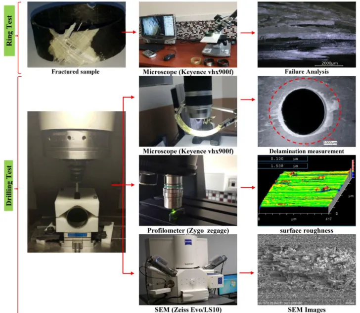
In this study, failure alaysis of fractured samples after ring tensile test was monitored using Keyence VHX-900F digital microscope. After drilling test, drilling induced delamination, borehole surface topo-graphy, and borehole damages were examined using Keyence VHX-900F digital microscope, Zygo ZeGage optical profilometer, and Zeiss Evo LS10 scanning electron microscope (SEM) (Fig. 1). Delamination factor was used in assessment of drilling induced delamination and calculated as the ratio of the maximum diameter (Dmax) of the observed
damaged zone to the nominal diameter of the hole (Dnom)[55]. Since it
is more severe than peel-up, push-out delamination is evaluated. After measuring drilling induced push-out delamination damage, holes were divided in two from the axis and borehole surfaces were examined with SEM in order to determine damage modes.
3. Experimental results and discussion 3.1. Ring tensile test damage analysis
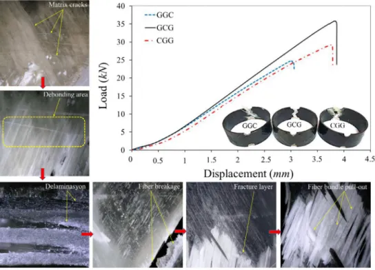
To determine the mechanical properties of the hybrid pipes, ring tensile test was performed according to ASTM D2290 standards. The ring tensile test was repeated three times for each specimen (GCG, CGG, and GGC). Fig. 2 compares the load-displacement curves of hybrid composite pipes in different stacking sequences. It is apparent from this figure that reproducibility is better in GCG and CGG samples compared to GGC specimen since the GGC sample presented a more unstable behavior. For the hybrid composite pipes, the stacking of the carbon Fig. 2. Load-displacement curves for reproducibility.
layer on the top of the pipe leads to not only decreasing in the me-chanical properties but also leading unstable meme-chanical behaviour.
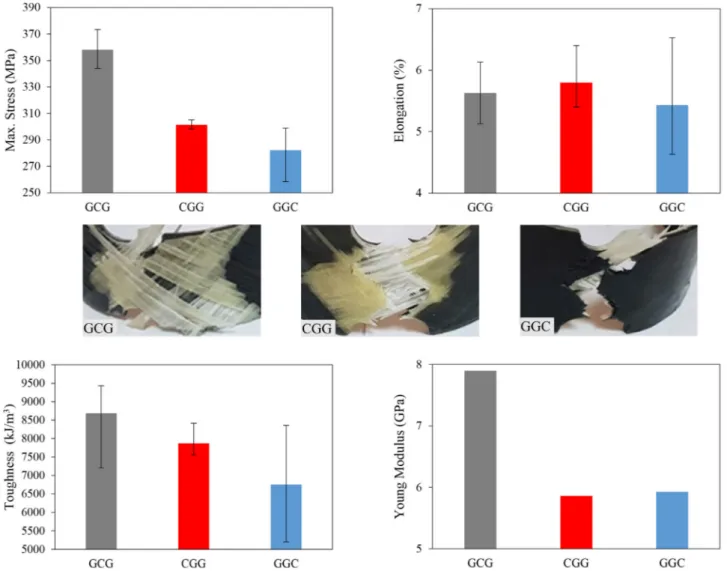
Maximum tensile stress, elongation, toughness and Young modulus of the hybrid pipes were given inFig. 3. The data obtained during the ring tensile tests were recorded and the damages occurred during the tests were observed. After the ring tensile tests, the damages in the all three pipes were examined with digital optical microscope and detailed damage analysis was performed. The kinetic analysis of the damages formed in hybrid composite pipes during ring tensile test was presented in Fig. 4. The order of development of principal damages was de-termined for all specimens during the ring tensile test. Thefirst damage is the formation of surface matrix cracks in the axial direction [7,39,58–60]. With the increasing of displacement, in thefiber direc-tion, matrix cracks, debonding, crazing (whitening), delaminadirec-tion,fiber breakage, fracture layer,fiber bundle pull-out or layer pull-out damages are formed, respectively. The images taken from the outer surface, inner surface and reduced section area of the damaged zone for the pipes were given inFig. 5.
In the GCG sample, a severe damage occurs at a high tensile stress value of 358 MPa. Prior to reaching the resulting damage, crazing (whitening) caused by debonding is observed in the glass layers in the reduced section. The failure occurs by the brittle fracture of the carbon layer and glass layer stacked on the inner surface of the pipe. When the images taken from the outer surface of the pipe are examined; it is observed that a large delamination area with surface matrix cracks was formed intensively in the glass layer at the direction offiber winding
angle ( ± 55°). The resulting surface matrix cracks progress in the layer and caused to damage of glassfiber bundles. Following, a brittle frac-ture is observed on the inner surface of the GCG pipe at +55° glass layer, and a smaller delamination area was observed relative to the outer surface. High tensile levels are reached in this sample (GCG) and the resulting damage was caused byfiber breakage damage rather than delamination damage. This is due to the fact that the carbon layer was stacked between two glass layers. When the reduced section is ex-amined, it is seen that the carbon layer broke andfiber breakage da-mages were formed and then dada-mages progressed in glass layers.
Besides the surface matrix cracks form in thefiber direction on the outer surface of the CGG pipe, it is seen that cracks parallel to the loading direction occur in the resin rich regions. It is observed thatfiber breakage damage occurs due to pull-out of ± glass fiber bundles. When the inner surface of the CGG pipe is examined, it is observed that the carbon layer exhibited a brittle fracture in thefiber direction. After the failure of carbon layer, similar damages are formed in glass layers and failure occurred at lower stress values and smaller delaminations compared to the GCG specimen.
In the GGC sample, it is observed that matrix cracks are formed in the carbon layer through the loading direction on the outer surface of the pipe. When the inner surface of the GGC pipe is examined, it is seen that a more distinct and wider delamination area are formed compared to GCG and CGG samples. The formation of a wider delamination area as well as the presence of clear debonding areas within the delamina-tion area indicates a different type of damage compared to the previous
samples. Unlike GCG and CGG samples, in GGC sample, it is seen that the carbon and glass layers showed pull-out (pull-out glass/carbon layers) damage rather thanfiber bundles pull-out. In this case, the be-ginning of the damage started with the damage of the carbon layer. Since the carbon layer is stacked on the outer surface of the pipe, it breaks at a lower tensile strength value (282.1 MPa) than that of GCG and CGG samples. InFig. 5, GCG and CGG samples exhibit thatfiber breakage, fiber bundle pull-out, layer breakage and brittle fracture damages are more intense. But a common damage formation is ob-served for all cases as a crack path forms in the reduced section and the crack propagates.
3.2. Drilling induced push-out delamination analysis
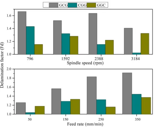
The influence of a change in spindle speed and feed rate on push-out delamination damage was illustrated inFig. 6. It is stressed in the lit-erature that more damages formed in drilling composite tube/pipe than that of composite plates[52,61]. The results of this work are consistent with the highlighted statement. Delamination factors could not be de-termined since there are larger delaminated areas in holes drilled without utilizing back-up. When drilling induced push-out delamina-tion damages evaluated in terms of pipes (specimen), it can be said that the most damage was formed in GCG specimen while the least dela-mination occurred in CGG specimen. WhenFig. 6is examined, it is seen that delamination factor is decreased depending on an increase in spindle speed. Higher feed rates leads generating larger thrust forces and these higher forces create a larger bending deformation in the layer beneath drill bit. When delamination occurs, stored energy due to bending is released as surface energy[52].
Images of hole exit damages (delaminated areas) generated in hy-brid composite pipes were monitored with Keyence VHX 900-F digital microscope (Fig. 7). It is obvious that much more damage forms in drilling without back-up. The reason of this was clarified by Hocheng and Tsao et al.[52,62]as that the back-up provides a protection against the bending deformation to the last ply which is pushed by cutting tool and increases rigidity. When specimens drilled without back-up are compared, it is seen that the most damaged is GCG pipe while the least damage is observed in CGG pipe. Besides, it was observed that there is
an unacceptable level of delamination damage in drilling GGC and GCG pipe without back-up. When drilled holes using back-up are examined in terms of severity of delamination, the least damage is occurred in CGG pipe and this is followed by GGC pipe and GCG pipe, respectively. On the other hand, it is noticed that the damages are formed generally in the direction offilament winding (at 55° winding angle), moreover, glassfiber lamina is more sensitive to bending deformation and dela-mination damage. When carbonfiber lamina is located in the hole exit namely the last ply, less damages is formed but if glass lamina is stacked as the last ply, much more damage occurs.
3.3. Damage mechanisms during drilling in hybrid composite pipes The delamination mechanism occurred at the hole entry and hole exit of the hybrid composite pipes and the fracture modes that cause delamination are shown schematically inFig. 8. When the drill contacts the layers of composite material, the drill generates a peeling force along the cutting edges (Fig. 8b). The resulting peeling force causes the peel-up delamination in the composite pipe by delaminating the top plies with the effect of mod III (tearing shear). In addition, the end portions of thefibers in the top layer cannot cut properly due to un-favorable cutting conditions, such as vibrations in the cutting tool, and thefiber fringers begin to separate from the matrix in the direction of the winding with the mod I (opening cracks) effect, which is caused the delamination. Therefore, it can be said that both mode I and mode III are effective in the formation and progression of peel-up delamination [63].
Fig. 8c and d shows push-out delamination mechanism that occurs at the hole exit due to the thrust force during drilling. As the drill ap-proaches the last ply, the uncut layers become more susceptible to bending and deformation due to the reduced thickness of layers. As a result, the push-out delamination occurs when the interlayer stress rises above the interlayer bonding strength[63–67]. The delamination in the inner surface layers of the composite pipe occurs by both mode I and mode II effects due to the axial force and bending of the layers in drilling. Push-out delamination is more critical than peel-up delami-nation since there is no back-up force to compensate for the thrust force generated during the drilling process. Therefore, in this study, Fig. 4. Damage history of hybrid composite pipes for ring tensile test.
comparative and detailed damage analysis were performed by using back-up in drilling of composite pipes in order to minimize push-out delamination.
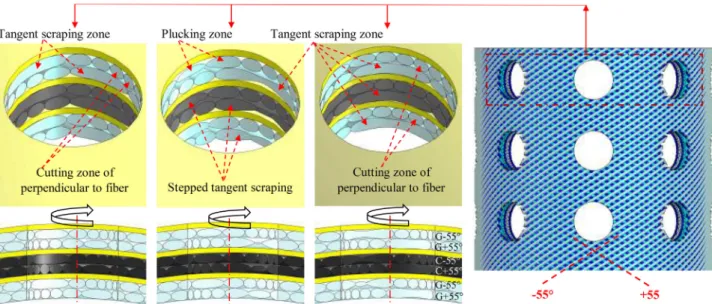
In drilling of hybrid composite pipes, the damage zones that occur in the boreholes at different layers depending on the fiber winding configuration of ± 55° are given schematically inFig. 9. Damages in the bore hole surface play a decisive role on the hole surface quality and delamination formation. In the hole, it is determined with SEM analysis
that there are four distinct damage zone type due to machining: tangent scraping zone (Fig. 9a), plucking zone (Fig. 9b), cutting zone of per-pendicular to fiber (Fig. 9c), and stepped tangent scraping zone (Fig. 9d). Depending on the winding angle, tangent scraping zone, plucking zone, and stepped tangent scraping zone occur due to in-tensive debonding betweenfiber and matrix, debonding, pull-out and fiber breakage mechanisms.
Location of the holes drilled on the composite pipe as well as the Fig. 5. The damages formed in GCG, CGG and GGC hybrid pipes.
fiber winding configuration plays a decisive role on the formation and location of the aforementioned damage zones.Fig. 10shows schema-tically the variation of the damages in the hole depending on a hole position. As a result, it is found that in the drilling of hybrid composite pipes, the location of the hole, fiber winding configuration, layer thicknesses, and stacking sequence influence damages at the hole en-trance, borehole and hole exit.
3.4. Hole exit damage analysis
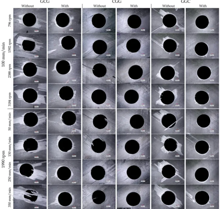
The effects of cutting parameters, stacking sequence, and the back-up usage on damage formation in drilling hybdrid composite pipes were observed using a digital microscope. The hole drilled with the 3184 rpm spindle speed and the 100 mm/min feed rate combination and the hole drilled with 1990 rpm spindle speed and 350 mm/min feed rate were examined. The influence of back-up use was also investigated. When Fig. 11 is examined, it is seen that push-out delamination damages occur in thefiber bundles through the direction of winding angle with different sizes and shapes. It is found that this type of damage severely forms at the hole exits of hybrid composite pipes in +55° layers. When the back-up used, it is noticed that push-out delamination is minimized. Larger delamination occurs in GCG and GGC pipes compared to CGG. When a hole poistion coincide with the intersection points of +55° and −55° fiber bundles, push-out delamination is found to occur at both winding angles. This phenomenon shows that hole position is an ef-fective factor on the delamination formation in drilling of filament wound composite pipes. This damage type was illustrated in Fig. 11 during drilling of GGC pipe at 3184 rpm spindle speed without back-up. It is also noticed that push-out delamination damage caused by Mode I and Mode II is larger in drilling without back-up. Especially, the last ply at the hole exit bends due to Mod I effect during drilling. Therefore cutting operation cannot be performed completely. Uncutfibers were observed intensively at the hole exits of +55° glass layers and in the tests performed at high feed rates without back-up (Fig. 11). Fiber protrusions occur at the hole edges when the cutfibers extend towards the center of the hole by debonding or thefibers are not fully separated
from the matrix. This damage was observed at the exit of holes drilled using back-up (Fig. 11). In the drilling test of GCG sample performed with high feed rate and low spindle speed without the back-up, larger delaminations occur at the hole exits. Infilament wound composite pipes, delamination damage occurs in the form of an elliptical area by expanding around the hole in the direction of winding angle.
3.5. Borehole damage SEM examination
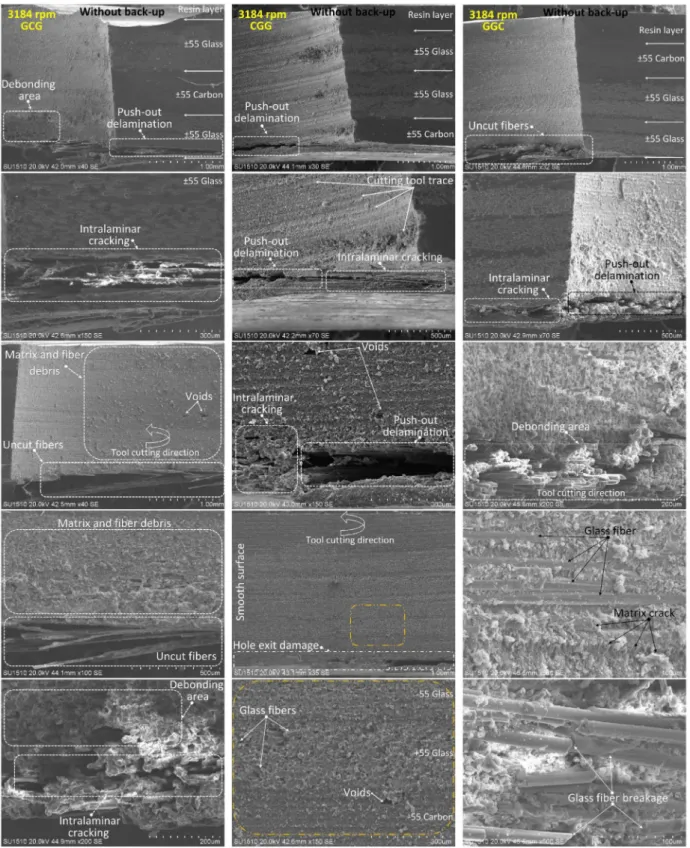
When the borehole damages are examined with SEM in macro size; the carbon layer was found to perform better performance than the glass layer against the formation of delamination and other damages. Similarly, the carbon layer presents better surface quality. This phe-nomenon can be clarified that rigidity of carbon fiber is higher while the diameter of the carbonfiber is lower compared to the glass fibers. Fig. 12shows bore hole damage examination of the GCG, CGG and GGC pipes drilled at 3184 rpm spindle speed and 100 mm/min feed rate without back-up (Fig. 12a) and with back-up (Fig. 12b). In general, all pipes show less damage in the tests performed using back-up. In par-ticular, push-out delamination is minimal and intralaminar cracks were also very little.
InFig. 12afor GCG specimen, it is observed that the damages are formed in push-out delamination zone. Delaminations formed at the exit of the hole progress into the layer and propagate as intralaminar cracks. Detailed SEM images were obtained to monitor intralaminar crack damage. When the cracks are examined, it is clearly seen that micro-matrix cracks and debonding damages occur. It is also observed that a large delamination area forms around the center of the in-tralaminar fracture. Uncutfibers are observed in the inner layer which are bent due to the push-out delamination. Fiber and matrix debris are seen on the entire inner surface of the hole but they formed more in-tensely around +55° glass layer. InFig. 12bfor GCG specimen, it is seen that small amounts of hole exit damages (push-out delamination and intralaminar crack) occur in a narrow area. In addition, no other damage mode is formed but it is observed that glassfiber breakage occurs in +55° glass layer.
Fig. 6. Effect of cutting parameters on push-out delamination in composite pipes drilling with back-up.
When SEM images of CGG sample are examined (Fig. 12a), it is seen that push-out delamination and intralaminar cracking are formed in the +55° carbon layer at the hole exit. In the inner surface of the hole wherefiber configuration is effective on, cutting tool trace is obvious, but in general, a smooth surface is formed. WhenFigs. 11and12aare examined together for CGG sample, it is noticed that the carbon layer prevents the formation of uncutfiber and debonding area if stacked on the inner surface of the pipe. When the back-up used (Fig. 12b), SEM images of CGG sample indicates that there are matrix andfiber debris in carbon layers and a rough surface is formed in the resin rich area on the outer surface of the hybrid pipe. Also, cutting tool traces are observed in inter-layer resin-rich areas on the inner surface of the hole. The use of back-up and stacking of the carbon layer on the inner surface of the pipe prevents the formation of other damage modes.
When SEM images of GGC sample are examined inFig. 12a, in-tralaminar crack and delamination damages are observed intensely around the +55° glass layer, as in the GCG sample.Figs. 11and12 shows that the hole drilled at the intersection point of ± 55° glass layer
caused damage in both winding angle directions. In addition to uncut fibers, debonding, micro-matrix cracks and glass fiber breakages are intensively observed in the borehole surface of ± 55° glass layers in the GGC sample. Similar damages are observed during drilling of GGG pipe in another study published by Gemi et al.[68]. In the case of using back-up during drilling of GGC sample, it is seen that the surface was similar to that of CGG sample (Fig. 12b). Damages caused by cutting are seen on the inner surface and the edges of the hole. In the drilling tests using back-up, the chips formed during drilling moved to the opposite direction of feed and caused chip plastering on the inner surface of the hole. Therefore, matrix andfiber debris were observed on the hole surfaces in the drilling tests using back-up. Due to thefiber configura-tion, debonding andfiber breakage damage occurred partially in the tangent scraping zone.
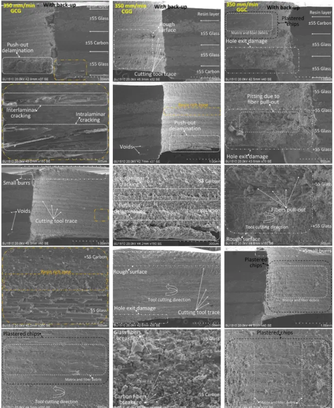
Fig. 13illustrates bore hole damage examination of the GCG, CGG and GGC pipes drilled at 350 mm/min feed rate and 1990 rpm spindle speed without back-up (Fig. 13a) and with back-up (Fig. 13b). When the images for GCG sample in Fig. 13a and Fig. 11 are evaluated Fig. 7. Images of hole exit damages produced in drilling hybrid composite pipes.
Fig. 8. Delamination mechanisms caused by drilling of hybrid composite pipes, a) initial of drilling, b) peel-up delamination (intralaminar), c) push-out delamination (interlaminar) and d) push-out delamination (intralaminar).
Fig. 9. Damage zones occurring in different layers in the bore hole according to the fiber winding configuration when drilling hybrid composite pipes, a) tangent scraping zone, b) plucking zone, c) cutting zone of perpendicular tofiber and d) stepped tangent scraping zone.
together, it is seen that all of the damage modes mentioned before are formed in this sample. GCG pipe differs from others in terms of the formation of push-out delamination and other damage modes. Peel-up delamination damage is also observed in the GCG pipe. It is also noticed that chips are collected in ± 55° glass, resin layer and peel-up area which leads a rough surface (Fig. 13a). Further SEM images of the in-tralaminar fracture region clearly show that the debonding damage is formed. When resin rich region between−55° glass and +55° carbon layer are examined, cutting tool trace and glass/carbonfiber breakages are monitored. When SEM images inFig. 13bfor GCG sample are ex-amined, it is seen that the interlaminar/intralaminar cracks are formed in ± 55° glass layers at the hole exit. In order to better define the in-terlaminar/intralaminar crack formation, detailed SEM analysis were carried out. Intralaminar cracks are formed in the +55° glass layer and
interlaminar cracks are formed between ± 55° glass layers. Small burr formation was observed with peel-up effect at the hole entrance. The use of back-up is found to be effective in the formation of small burr damage mode. The chips formed during the drilling are directed to-wards the hole entrance by the back-up effect and it is found that the chips stick to the hole surface and form plastered chips damage mode. It is belived that the accumulation of plastered chips at the hole exit is caused by heat. In all tests performed using the back-up, cutting tool trace formation is also observed.
In CGG sample, it was observed that plucking zones are formed on bore hole surfaces. It was determined that these regions formed in the −55° glass layer caused to be formed a rough surface. Debonding, pull-out andfiber breakage damage also occur in the rough surface area. Lower push-out delamination and intralaminar cracks occurred in the Fig. 10. The effect of hole positions on the pipe damage to the bore hole in the drilling of hybrid composite pipes.
hole exit. The stacking of the carbon layer on the inside of the pipe provides a back-up effect, which reduces the formation of hole exit damage and uncut fibers even at high feed rate. When Fig. 11and Fig. 13b are examined together, it is found that very small inter-laminar/intralaminar cracks are formed in the CGG pipe in ± 55° carbon layer and between the layers. These damages caused by push-out are observed as intralaminar crack at +55° carbon layer and in-terlaminar crack between ± 55° carbon layers. It is also observed that
push-out damage is reduced compared to formed in GCG pipe using back-up, but the chips are plastered on the inner surface of the hole and formed a rough surface. SEM images taken from the region where−55° carbon and +55° glass layers intersection show that glass/carbonfiber particles on the inner surface of the hole are found to be effective in rough surface formation. This is thought to result from the fact that the cutting edges are scraping rather than cutting due to the high feed rate. SEM images inFig. 13afor GGC sample indicate that interlaminar/ Fig. 12a. SEM images of bore hole damages for GCG, CGG and GGC hybrid pipes drilled without using back-up at 3184 rpm spindle speed and 100 mm/min feed rate,
intralaminar cracks as well as push-out delamination are formed at ± 55° glass layer. As formed in CGG pipe, a rough surface occurs in the plucking zone of +55° glass layer. Focusing on the intersection of ± 55° glass layers,fiber pull-out, debonding, micro-matrix crack and fiber breakage damage modes are observed in the plucking zone. A smooth surface is obtained in areas where carbon layers are stacked. When the SEM images of GGC pipe inFig. 13bare evaluated, it is ob-served that damages similar to the damage modes seen in GCG and CGG
pipes occur. Unlike other hybrid pipes, pitting due tofiber pull-out damage is observed in the GGC sample. This damage mode is seen in layers wherefibers are perpendicular to the cutting edges during cut-ting[69,70]. It is noticed that excessive pull-out damage occurs in these layers due to the forced pitting of thefibers rather than cutting. Fo-cusing on the pitting damage zone, it is observed thatfiber pull-out, debonding,fiber breakage and matrix crack were formed typically. It was determined that this type of damage occurs between ± 55° glass Fig. 12b. SEM images of bore hole damages for GCG, CGG and GGC hybrid pipes drilled using back-up at 3184 rpm spindle speed and 100 mm/min feed rate.
layers and deepens in intersection points of ± layers. Peel-up damage also occurs in the GGC pipe, which is not apparent in other samples. The SEM images of the GGC sample taken from the borehole section (Fig. 13b) showed that the−55° carbon layer and the resin layer are completely separated from the sample surface by peel-up damage.
3.6. Borehole surface quality
Surfacefinish is a substantial design characteristic in drilled parts therefore measuring surface roughness has a great importance in the manufacturing process[71,72]. The surface roughness is an essential factor for workpiece surface quality evaluation and it determines sur-face smoothness. Sursur-face roughness can influence fatigue strength, contact stiffness, and corrosion resistance of workpiece and Fig. 13a. SEM images of bore hole damages for GCG, CGG and GGC hybrid pipes drilled without using back-up at 1990 rpm spindle speed and 350 mm/min feed rate,
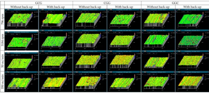
significantly improve cooperation. Moreover, surface roughness influ-ences the service life and reliability of machinery products [73–76]. The surface roughness of boreholes of drilled hybrid pipes was mea-sured to determine the surface quality of holes. In addition to surface roughness, surface topography of holes drilled with 796 and 3184 rpm spindle speed and 50 and 350 mm/min feed rate were monitored. Each hole was cut in half so that the borehole surface could be monitored. A 500x500 µm area in the drilled hole surface was examined. The 3D
surface topography taken from the hybrid pipes was given inFig. 14. For each hybrid pipes and different drilling parameters, surface roughness datas were obtained and given inFig. 15. The average of three measurements was calculated as the surface roughness value for each hole. In all cases, regardless of using back-up, surface quality is improved with increasing spindle speed and deteriorated with in-creasing feed rate. It is found that borehole surface quality of hybrid pipes is greatly improved in the case of using back-up during drilling. Fig. 13b. SEM images of bore hole damages for GCG, CGG and GGC hybrid pipes drilled using back-up at 1990 rpm spindle speed and 350 mm/min feed rate.
As can be seen from theFig. 15, lower feed rate, higher spindle speed, and the back-up utilization combination presents better surface quality by reducing surface roughness. While it is difficult to claim a general statement but it is seen that the best surface is formed in CGG and the worst surface is formed in the GCG sample depending on a change in spindle speed. When the effects of a change in feed rate on surface quality is evaluated, it can be said that the smoothest surface occurs in
GCG, while the roughest surface occurs in CGG. 4. Conclusion
Drilling machinability characteristics of filament wound hybrid composite pipes (GCG, CGG and GGC) were experimentally in-vestigated considering ring tensile test damage analysis, push-out Fig. 14. Surface topography of boreholes for GCG, CGG and GGC hybrid pipes.
Fig. 15. Surface roughness variation of boreholes for GCG, CGG and GGC hybrid pipes.
delamination analysis, damage modes and damage mechanisms of pipes, borehole surface damage examination and borehole surface quality. Following conclusions were drawn as below:
•
It is concluded from the results of this experimental study that stacking sequence of the composite pipes effects considerably da-mage modes and dada-mage mechanisms of pipes.•
Lower delamination damages occur at lower feed rates and higher cutting speeds as in machining of composite plates. Besides, the most damage is formed in GCG specimen.•
When filament wound composite pipes drilled without back-up, extreme push-out delamination and bending deformation are formed. Also, damages are formed generally in the direction of fi-lament winding (at ± 55° winding angle).•
If carbon layer is stacked to be the last ply (on the inner surface of the pipe), less push-out delamination is produced. Also, glass layer is more sensitive to delamination damage as compared to carbon.•
Even if the back-up increases thrust forces, it is recommended by the authors due to the fact that it reduces delamination damage con-siderably and prevents bending of the last ply.•
Lower feed rate, higher spindle speed, and back-up use combination presents better surface quality by reducing surface roughness.•
Depending on the position of hole, four different types of damage zones have been found to occur, namely, tangent scraping zone, plucking zone, perpendicular tofiber, and stepped tangent scraping zone. It is also found that these damage zones play a decisive role in hole surface quality and delaminations formation.•
A larger delamination area has formed in GGC sample after the ring test compared to GCG and CGG samples. The larger delamination and the formation of debonding damage in this area change the type of damage.•
In the damage analysis of ring tensile tests samples, it is seen that pull-out of carbon and glass layers have occurred rather thanfiber bundles pull-out in GGC unlike other samples. The stacking of the carbon layer on the outer surface of the pipe has caused resulting damage at a low tensile value and it is found that this stacking configuration has lowered the mechanical properties and altered the mechanism of occurrence and propagation of damage during loading.Declaration of Competing Interest
The authors declare that they have no known competingfinancial interests or personal relationships that could have appeared to influ-ence the work reported in this paper.
Appendix A. Supplementary data
Supplementary data to this article can be found online athttps:// doi.org/10.1016/j.compstruct.2019.111737.
References
[1] Aljuboury M, Rizvi MJ, Grove S, Cullen R. Bolted Flange Joint Made of Glass Fibre Reinforced Polymer (GFRP) for Oil and Gas Pipelines. ASME 2018 Pressure Vessels and Piping Conference. 2018;Volume 6A: Materials and Fabrication:V06ATA039. [2] Gemi L, Köroğlu MA, Ashour A. Experimental study on compressive behavior and
failure analysis of composite concrete confined by glass/epoxy ± 55° filament wound pipes. Compos Struct 2018;187:157–68.
[3] Mahdi E, Hamouda AMS, Sahari BB, Khalid YA. Effect of hybridisation on crushing behaviour of carbon/glassfibre/epoxy circular–cylindrical shells. J Mater Process Technol 2003;132(1):49–57.
[4] MazurkiewiczŁ, Małachowski J, Tomaszewski M, Baranowski P, Yukhymets P. Performance of steel pipe reinforced with composite sleave. Compos Struct 2018;183:199–211.
[5] Tarfaoui M, Gning PB, Davies P, Collombet F. Scale and size effects on dynamic response and damage of glass/epoxy tubular structures. J Composite Mater 2007;41(5):547–58.
[6] Tarfaoui M, Gning PB, Hamitouche L. Dynamic response and damage modeling of
glass/epoxy tubular structures: numerical investigation. Compos A Appl Sci Manuf 2008;39(1):1–12.
[7] Prabhakar MM, Rajini N, Ayrilmis N, Mayandi K, Siengchin S, Senthilkumar K, et al. An overview of burst, buckling, durability and corrosion analysis of lightweight FRP composite pipes and their applicability. Compos Struct 2019;111419.
[8] Deniz ME, Karakuzu R. Seawater effect on impact behavior of glass–epoxy com-posite pipes. Compos B Eng 2012;43(3):1130–8.
[9] Sahin ÖS, Akdemir A, Avci A, Gemi L. Fatigue crack growth behavior offilament wound composite pipes in corrosive environment. J Reinf Plast Compos 2009;28(24):2957–70.
[10] Sebaey TA. Design of oil and gas composite pipes for energy production. Energy Procedia 2019;162:146–55.
[11] Tarfaoui M, Gning P-B, Collombet F. Residual strength of damaged glass/epoxy tubular structures. J Compos Mater 2007;41(18):2165–82.
[12] Chen J, Zhen Y, Lou Y, Lv Y. Stiffness degradation of GFRP pipes under fatigue loading. Mater Test 2019;61(5):435–40.
[13] Deniz ME, Karakuzu R, Icten BM. Transverse impact and axial compression beha-viors of glass/epoxy pipes subjected to seawater and impact loading. Int J Damage Mech 2013;22(7):1071–85.
[14] Deniz ME, Karakuzu R, Sari M, Icten BM. On the residual compressive strength of the glass–epoxy tubes subjected to transverse impact loading. J Composite Mater 2012;46(6):737–45.
[15] Gemi L, Tarakçioğlu N, Akdemir A, Şahin ÖS. Progressive fatigue failure behavior of glass/epoxy ( ± 75)2filament-wound pipes under pure internal pressure. Mater Des 2009;30(10):4293–8.
[16] Rafiee R. Stochastic fatigue analysis of glass fiber reinforced polymer pipes. Compos Struct 2017;167:96–102.
[17] Rafiee R, Elasmi F. Theoretical modeling of fatigue phenomenon in composite pipes. Compos Struct 2017;161:256–63.
[18] Tarakçioğlu N, Gemi L, Yapici A. Fatigue failure behavior of glass/epoxy ± 55 fi-lament wound pipes under internal pressure. Compos Sci Technol
2005;65(3):703–8.
[19] Taşyürek M, Tarakçioğlu N. Enhanced fatigue behavior under internal pressure of CNT reinforcedfilament wound cracked pipes. Compos B Eng 2017;124:23–30. [20] Üstün T, Eskizeybek V, Avci A. Enhanced fatigue performances of hybrid
nanor-einforcedfilament wound carbon/epoxy composite pipes. Compos Struct 2016;150:124–31.
[21] Vieira PR, Carvalho EML, Vieira JD, Toledo Filho RD. Experimental fatigue beha-vior of pultruded glassfibre reinforced polymer composite materials. Compos B Eng 2018;146:69–75.
[22] Farhood NH, Karuppanan S, Ya HH, Ovinis M. Experimental study of low velocity impact response of carbon/basalt hybridfilament wound composite pipes. Int J Struct Stab Dyn 2018;18(07):1850089.
[23] Gemi L, Kayrıcı M, Uludağ M, Gemi DS, Şahin ÖS. Experimental and statistical analysis of low velocity impact response offilament wound composite pipes. Compos B Eng 2018;149:38–48.
[24] Gemi L. Düşük hızlı darbe hasarlı filaman sarım hibrid boruların iç basınç altında
yorulma davranışı PhD Thesis Konya2014.
[25] Krishnan P, Abdul Majid MS, Afendi M, Gibson AG, Marzuki HFA. Effects of
winding angle on the behaviour of glass/epoxy pipes under multiaxial cyclic loading. Mater Des 2015;88:196–206.
[26] Toh W, Tan LB, Tse KM, Giam A, Raju K, Lee HP, et al. Material characterization of filament-wound composite pipes. Compos Struct 2018;206:474–83.
[27] Xu J, Ma Y, Zhang Q, Sugahara T, Yang Y, Hamada H. Crashworthiness of carbon fiber hybrid composite tubes molded by filament winding. Compos Struct 2016;139:130–40.
[28] Gemi L. Filaman sarım CTP boruların iç basınç etkisi altında yorulma davranışı MSc Thesis Konya2004.
[29] Quanjin M, Rejab MRM, Idris MS, Kumar NM, Merzuki MNM. Robotic Filament Winding Technique (RFWT) in Industrial Application: A Review of State of the Art and Future Perspectives. Int Res J Eng Technol 2018;5(12):1668–76.
[30] Nachtane M, Tarfaoui M, El Moumen A, Saifaoui D. Damage prediction of hor-izontal axis marine current turbines under hydrodynamic, hydrostatic and impacts loads. Compos Struct 2017;170:146–57.
[31] Nachtane M, Tarfaoui M, Saifaoui D, El Moumen A, Hassoon OH, Benyahia H. Evaluation of durability of composite materials applied to renewable marine en-ergy: case of ducted tidal turbine. Energy Rep 2018;4:31–40.
[32] Gemi L. Investigation of the effect of stacking sequence on low velocity impact response and damage formation in hybrid composite pipes under internal pressure. A comparative study. Compos B Eng 2018;153:217–32.
[33] Gemi L, Kara M, Avci A. Low velocity impact response of prestressed functionally graded hybrid pipes. Compos B Eng 2016;106:154–63.
[34] Gemi L, SinanŞahin Ö, Akdemir A. Experimental investigation of fatigue damage formation of hybrid pipes subjected to impact loading under internal pre-stress. Compos B Eng 2017;119:196–205.
[35] Gemi L, Aksoylu C, YazmanŞ, Özkılıç YO, Arslan MH. Experimental investigation of shear capacity and damage analysis of thinned end prefabricated concrete purlins strengthened by CFRP composite. Compos Struct 2019;229:111399.
[36] Eggers F, Almeida JHS, Azevedo CB, Amico SC. Mechanical response offilament wound composite rings under tension and compression. Polym Test
2019;78:105951.
[37] Shabani P, Taheri-Behrooz F, Maleki S, Hasheminasab M. Life prediction of a not-ched composite ring using progressive fatigue damage models. Compos B Eng 2019;165:754–63.
[38] Rafiee R. Apparent hoop tensile strength prediction of glass fiber-reinforced polyester pipes. J Compos Mater 2013;47(11):1377–86.
[39] Benyahia H, Tarfaoui M, El Moumen A, Ouinas D, Hassoon OH. Mechanical prop-erties of offshoring polymer composite pipes at various temperatures. Compos B Eng 2018;152:231–40.
[40] Kaynak C, Salim Erdiller E, Parnas L, Senel F. Use of split-disk tests for the process parameters offilament wound epoxy composite tubes. Polym Test
2005;24(5):648–55.
[41] Xia M, Takayanagi H, Kemmochi K. Analysis of multi-layeredfilament-wound composite pipes under internal pressure. Compos Struct 2001;53(4):483–91. [42] Mertiny P, Ellyin F. Influence of the filament winding tension on physical and
mechanical properties of reinforced composites. Compos A Appl Sci Manuf 2002;33(12):1615–22.
[43] Hwang T-K, Hong C-S, Kim C-G. Size effect on the fiber strength of composite pressure vessels. Compos Struct 2003;59(4):489–98.
[44] Abilash N, Sivapragash M. Optimizing the delamination failure in bamboofiber reinforced polyester composite. J King Saud University– Eng Sci
2016;28(1):92–102.
[45] Campos Rubio J, Abrao AM, Faria PE, Correia AE, Davim JP. Effects of high speed in the drilling of glassfibre reinforced plastic: Evaluation of the delamination factor. Int J Mach Tools Manuf 2008;48(6):715–20.
[46] Faraz A, Biermann D, Weinert K. Cutting edge rounding: an innovative tool wear criterion in drilling CFRP composite laminates. Int J Mach Tools Manuf 2009;49(15):1185–96.
[47] Giasin K, Ayvar-Soberanis S. Microstructural investigation of drilling induced da-mage infibre metal laminates constituents. Compos A Appl Sci Manuf 2017;97:166–78.
[48] Giasin K, Ayvar-Soberanis S. An investigation of burrs, chip formation, hole size, circularity and delamination during drilling operation of GLARE using ANOVA. Compos Struct 2017;159:745–60.
[49] Liu D, Tang Y, Cong WL. A review of mechanical drilling for composite laminates. Compos Struct 2012;94(4):1265–79.
[50] Shetty N, Shahabaz SM, Sharma SS, Divakara Shetty S. A review onfinite element method for machining of composite materials. Compos Struct 2017;176:790–802. [51] Sorrentino L, Turchetta S, Bellini C. A new method to reduce delaminations during drilling of FRP laminates by feed rate control. Compos Struct 2018;186:154–64. [52] Hocheng H, Tsao CC, Chen HT. Utilizing internal icing force to reduce delamination
in drilling composite tubes. Compos Struct 2016;139:36–41.
[53] Liu G, Chen H, Huang Z, Gao F, Chen T. Surface quality of staggered PCD end mill in milling of carbonfiber reinforced plastics. Appl Sci 2017;7(2):199.
[54] Zitoune R, Collombet F, Lopez GH. Experimental and analytical study of the in-fluence of HexFit® glass fibre composite manufacturing process on delamination during drilling. Int J Mach Mach Mater 2008;3(3–4):326–42.
[55] Geng D, Liu Y, Shao Z, Lu Z, Cai J, Li X, et al. Delamination formation, evaluation and suppression during drilling of composite laminates: a review. Compos Struct 2019;216:168–86.
[56] Meram A, Can A. Experimental investigation of screwed joints capabilities for the CFRP composite laminates. Compos B Eng 2019;176:107142.
[57] Tsao CC, Hocheng H. Effects of exit back-up on delamination in drilling composite
materials using a saw drill and a core drill. Int J Mach Tools Manuf 2005;45(11):1261–70.
[58] Özbek Ö, Bozkurt ÖY. Hoop tensile and compression behavior of glass-carbon in-traply hybridfiber reinforced filament wound composite pipes. Materials Testing. 2019;61(8):763–9.
[59] Kangal S, Kartav O, Tanoğlu M, Aktaş E, Artem HS. Investigation of interlayer
hybridization effect on burst pressure performance of composite overwrapped pressure vessels with load-sharing metallic liner. Journal of Composite Materials. 0(0):0021998319870588.
[60] Benyahia H, Tarfaoui M, Datsyuk V, El Moumen A, Trotsenko S, Reich S. Dynamic properties of hybrid composite structures based multiwalled carbon nanotubes. Compos Sci Technol 2017;148:70–9.
[61] Hocheng H, Tsao CC, Liu CS, Chen HA. Reducing drilling-induced delamination in composite tube by magnetic colloid back-up. CIRP Ann 2014;63(1):85–8. [62] Tsao CC, Hocheng H, Chen YC. Delamination reduction in drilling composite
ma-terials by active backup force. CIRP Ann 2012;61(1):91–4.
[63] Girot F, Dau F, Gutiérrez-Orrantia ME. New analytical model for delamination of CFRP during drilling. J Mater Process Technol 2017;240:332–43.
[64] Anand RS, Patra K. Mechanistic cutting force modelling for micro-drilling of CFRP composite laminates. CIRP J Manuf Sci Technol 2017;16:55–63.
[65] Caggiano A, Improta I, Nele L. Characterization of a New Dry Drill-Milling Process of Carbon Fibre Reinforced Polymer Laminates. Materials. 2018;11(8):1470. [66] Curiel-Sosa JL, Tafazzolimoghaddam B, Zhang C. Modelling fracture and
delami-nation in composite laminates: energy release rate and interface stress. Compos Struct 2018;189:641–7.
[67] Erturk AT, Vatansever F, Yarar E, Karabay S. Machining behavior of multiple layer polymer composite bearing with using different drill bits. Compos B Eng 2019;176:107318.
[68] Gemi L, Morkavuk S, Köklü U, Gemi DS. An experimental study on the effects of various drill types on drilling performance of GFRP composite pipes and damage formation. Compos B Eng 2019;172:186–94.
[69] Mulazimoglu H, Haylock L. The effect of machining-induced micro texture on lightning current arcing between fasteners and composite structure. SAE Int J Aerosp 2009;2(1):232–40.
[70] Mulazimoglu H, Haylock L. Recent developments in techniques to minimize light-ning current arcing between fasteners and composite structure. International Conference on Lightning and Static Electricity. 2011.
[71] Morkavuk S, Köklü U, Bağcı M, Gemi L. Cryogenic machining of carbon fiber re-inforced plastic (CFRP) composites and the effects of cryogenic treatment on tensile properties: a comparative study. Compos B Eng 2018;147:1–11.
[72] Palanikumar K. Experimental investigation and optimisation in drilling of GFRP composites. Measurement 2011;44(10):2138–48.
[73] Can A. Effect of edge trimming parameters on surface quality of carbon fiber. AKU J Sci Eng. 2017;17:302–11.
[74] Can A. Study on the machinability of SMC composites during hole milling: influence of tool geometry and machining parameters. Arab J Sci Eng 2019;44(9):7599–616.
https://doi.org/10.1007/s13369-019-03865-z.
[75] Geng D, Teng Y, Liu Y, Shao Z, Jiang X, Zhang D. Experimental study on drilling load and hole quality during rotary ultrasonic helical machining of small-diameter CFRP holes. J Mater Process Technol 2019;270:195–205.
[76] Yin Q, Li C, Zhang Y, Yang M, Jia D, Hou Y, Li R, Dong L. Spectral analysis and power spectral density evaluation in Al2O3 nanofluid minimum quantity lubrica-tion milling of 45 steel. Int J Adv Manuf Technol 2018;97(1-4):129–45.https://doi. org/10.1007/s00170-018-1942-9.
[77] Li Z, Zhang D, Qin W, Geng D. Feasibility study on the rotary ultrasonic elliptical machining for countersinking of carbonfiber–reinforced plastics. Proc. Inst. Mech. Eng. B-J. Eng. Manufact. 2017;231:2347–58.https://doi.org/10.1177/ 0954405415626086.