ISTANBUL UNIVERSITY ENGINEERING FACULTY JOURNAL OF ELECTRICAL & ELECTRONICS
YEAR VOLUME NUMBER : 2002 : 2 : 2 (547-553) Received Date : 6.2.2002 Accepted Date: 29.5.2002
NEW HIGH PERFORMANCE REALIZATIONS FOR
CURRENT-CONTROLLED CONVEYOR (CCCII)
Shahram MINAEI
1Deniz KAYMAK
2Hakan KUNTMAN
31
Dogus University, Faculty of Engineering, Department of Electronics and Communications Engineering, 81010, Acibadem, Kadikoy, Istanbul, TURKEY.
2,3
Istanbul Technical University, Faculty of Electrical and Electronics Engineering, Department of Electronics and Communication Engineering, 80626, Maslak, Istanbul, TURKEY.
1E-mail: [email protected] 2E-mail: [email protected] 3E-mail: [email protected]
ABSTRACT
In this paper two new realizations, one CMOS and one bipolar, fo r current-controlled conveyor (CCCII) are proposed. The proposed circuits provide a good linearity, very high input impedance at port-y, high output impedance at port-z and good output/input current gain. SPICE simulation results using TUBITAK 3µ CMOS process model are included to verify the expected values.
Keywords:. CMOS Circuits, CCCII
1. INTRODUCTION
Great interest has been devoted to the analysis and design of second generation current conveyor proposed by Sedra [1-2], mainly because it exhibits better performance, particularly higher speed and better bandwidth, than classic voltage-mode operational amplifiers, which are limited by a constant gain-bandwidth product [3-4]. On the other hand the recently introduced second-generation current-controlled conveyor (CCCII) [5-6] has the advantage of electronic adjustability over the current conveyor (CCII). Therefore there is a growing interest in the design of filters and oscillators using CCCIIs
[7-11]. A number of circuit configurations for CCCIIs have been produced [5-6,12]. Although these circuits have a simple configuration, they suffer from low input impedance at port-y and low output impedance at port-z of the conveyor. In this paper, two new circuits for realizing the CCCII are presented, each one with very small input impedance at port-x, a very high input impedance at port-y, a good linearity and high input/output gain ratio for current transfer. The resistances at port -x of the proposed CCCIIs, which can be controlled by adjusting the bias currents of the CCCIIs, are calculated theoretically. Simulation results, which confirm
548
the performance of the proposed CCCIIs, are included.
2. PROPOSED CIRCUITS
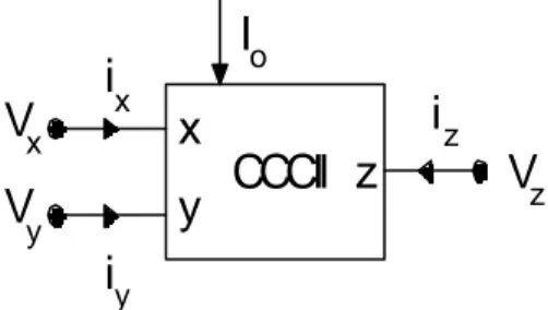
The port relations of an ideal CCCII, which is shown in Figure 1, can be given by
±
=
z x y x z x yv
i
v
R
i
v
i
0
1
0
0
1
0
0
0
(1)where the positive and negative signs define a positive and negative current-controlled conveyor, respectively. The input resistance RX at terminal x is proportional to 1/IO for BJT realizations [5] and proportional to 1/ IO for CMOS realizations [12] so that it is possible to control its value by changing the biasing current IO.
CCCII
x
y
z
V
xV
yV
zi
yi
xi
zI
oFigure 1. Electrical symbol of the CCCII.
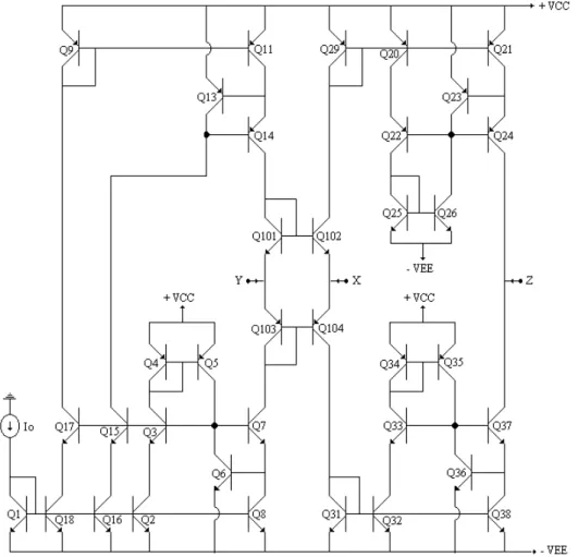
The first proposed circuit, which is illustrated in Figure 2, is constructed with bipolar active feedback cascade current mirrors [13].
The conveyor x-input impedance is calculated as [5]
2I
V
I
V
V
R
o T x y x x=
−
=
(2)Thus, the x-input impedance can be controlled by the bias current Io.
The z-output impedance of the proposed conveyor is calculated as
Rz = [gm36.gm37.ro38.ro37.(ro36 // ro35)] // [gm23.gm24.ro21.ro24.(ro23 // ro26)] (3) where gmi and rdsi denote the transconductance and output resistance of the transistor numbered
the proposed conveyor has a very high z-output impedance.
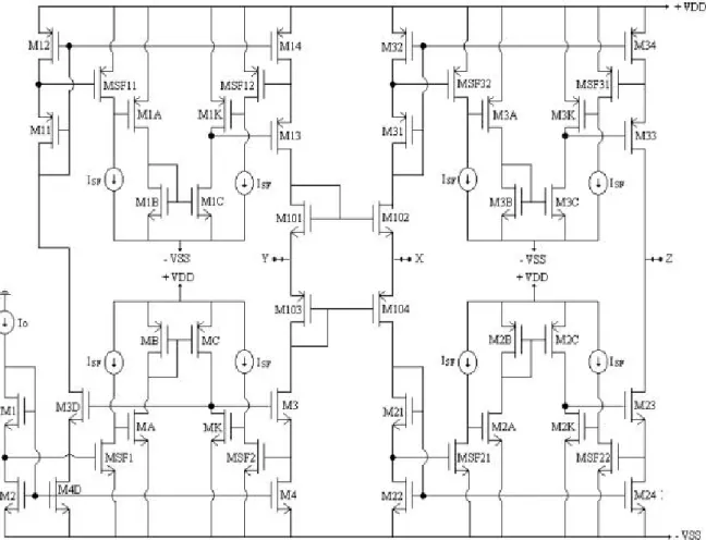
The second proposed circuit shown in Figure 3 is based on improved active feedback compact cascode current mirrors [14]. A major advantage of this circuit is that the output conductance and the feedback capacitance are lower 100 times than the standard current mirror circuit. The conveyor x-input impedance is calculated as Rx = (gm102 + gm104 + gmbs102 + gmbs104 )-1≅ (gm102 +
gm104)-1 (4) and z-output impedance is calculated as
Rz≅[gm23.gm2k.gmsf22.rds23.rds24.(rds2k//r2c). (rdsf22//rosi)]//[gm33.gm3k.gmsf32.rds33.rds34. (rds3k//r3c).(rdsf32 // rosi )] (5) where gmi, gmbsi, and rdsi denote the transconductance, body effect transconductance, output resistance of the MOS transistor numbered i, respectively. The rosi is the input impedance of the current source ISF.
Thus, the x-input impedance is very low and the z-output impedance is very high.
A current controlled conveyor with negative current transfer (CCCII-) can be obtained easily by adding two cross-coupled current mirror for the circuit shown in Figure 2 and two cross-coupled output stages for the circuit shown in Figure 3, in order to reveres the sign of current Iz.
3. SIMULATION RESULTS
The performance of the proposed circuits of CCCII+ is verified by SPICE simulation program using NR100N ve PR100N bipolar transistors parameters [15] for the first circuit and 3 µm TUBITAK CMOS transitor process model parameters for the second circuit. The dimensions of the MOS transistors used for SPICE simulations of the circuit in Figure 3 are given in Table 1. The voltage supply used for the CCCII given in Figure 2 is ±3.75 V with the bias current Io =40µA. For the CMOS CCCII given in Figure 3 the supply voltage is ±5V and the bias current is Io =50µA.
The basic dc and ac characteristics such as plots o f Vx against Vy,, plots of Vz against Vy and
549 frequency response of Iz/Ix for the first and
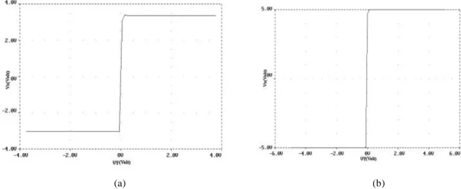
second circuits are obtained by SPICE simulations. The DC transfer characteristics of Vx against Vy (short circuited terminal z) for the both circuits are shown in Figure 4.
The voltage clipping limits at terminal-x are obtained as: Vxmax=2.84 V and Vxmin=-2.83 V for the first circuit and Vxmax=4.46 V and Vxmin =-4.36 V for the second circuit. Figure 5 shows the DC voltage transfer characteristic Vz-Vy from the input terminal y to the output terminal z for Rz=∞ (open circuit) and short-circuited terminal x. The voltage clipping limits determined as: Vzmax=3.35 V Vzmin=-3.02 V for the first circuit a n d Vzmax=5 V and Vzmin=-5 V for the second circuit.
Table 1. Transistors aspect ratios
The second proposed circuit M101,M102,M2,M4, M22,M24,M4D
W=30
µ
L=3
µ
M1,M3,M3D,M21, M23W=450
µ
L=3
µ
MSF1,MSF2,MSF21, MSF22W=200
µ
L=3
µ
MA,MB,MC,MK, M2A,M2B,M2C,M2KW=300
µ
L=9
µ
M103,M104,M12,M14, M32,M34W=60
µ
L=3
µ
M11,M13,M31,M33W=900
µ
L=3
µ
MSF11,MSF12,MSF31, MSF32W=400
µ
L=3
µ
M1A,M1B,M1C,M1K, M3A,M3B,M3C,M3KW=600
µ
L=9
µ
550
Figure 3. Second proposed circuit for the CCCII.
551
(a) (b)
Figure 5. The relation between Vz-Vy for (a) The first circuit (b) The second circuit.
Figure 6.The frequency response of the current follower (Iz, and Ix) for (a) The first circuit (b) The second circuit.
552
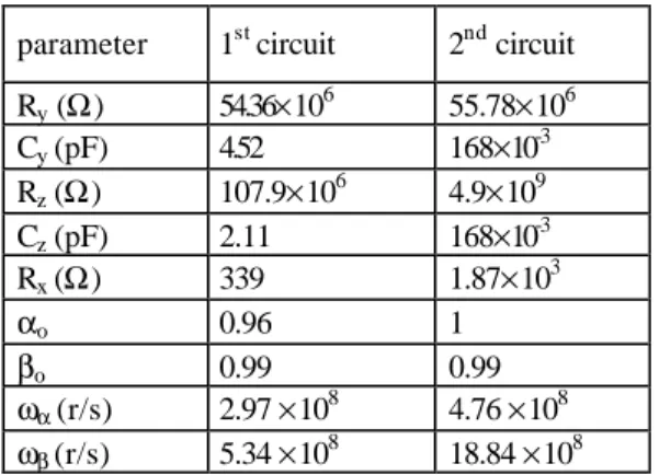
The frequency responses of the current follower configuration of the proposed CCCIIs are shown in Figure 6. Table 2 gives the simulated results obtained from the voltage follower and the current follower configurations of the proposed CCCIIs. In this table, αo and βo are respectively the current and voltage transfer gains of the conveyor at low frequencies. ωα and ωβ are the poles of the current and voltage transfer gains, respectively. The results confirm high performance of the proposed circuits.
Table 2. Simulation results
parameter 1st circuit 2nd circuit Ry (Ω) 54.36×10⁶ 55.78×10⁶ Cy (pF) 4.52 168×10-3 Rz (Ω) 107.9×10⁶ 4.9×10⁹ Cz (pF) 2.11 168×10-3 Rx (Ω) 339 1.87×10³ αo 0.96 1 βo 0.99 0.99 ωα(r/s) 2.97 ×10⁸ 4.76 ×10⁸ ωβ(r/s) 5.34 ×10⁸ 18.84 ×10⁸
4. CONCLUSION
Two new realizations of the current-controlled conveyor are presented. The resistance values at port-x of the proposed circuits have been calculated. The simulation results confirm high performance of the circuits in terms of good linearity and wide bandwidths both in voltage and current operations.
REFERENCES
[1] Roberts, G.W., Sedra, A.S., “All Current-Mode Frequency Selective Circuits”, Electronics Letters, Vol. 25, pp.759-761, 1989.
[2] Wilson, B., “Recent Developments in Current Conveyor and Current Mode Circuits”, Proceedings of IEE. G, Vol.137, pp. 63-77, 1990.
[3] Toumazou, C., Lidgey, F.J., Makris, C.A., “Extending voltage-mode op-amp to current-mode performance”, Proc. Inst. Elect. Eng., pt. G-137, Vol.137, pp. 116-130, 1990.
[4] Toumazou, C., Mahattanakul, J., “A Theoretical Study of the Stability of
High-Frequency Current Feedback Op-Amp Integrators,“ Trans. Circuit Syst. I, Vol.43, pp. 2-12, 1996.
[5] Fabre, A., Saaid, O., Wiest, F., Bouchron, C., “High Frequency Applications Based on a New Current Controlled Conveyor”, IEEE Transactions on Circuits and Systems -I: Fundamental Theory and Applications, Vol. 43, pp. 82-91, 1996.
[6] Fabre, A., Saaid, O., Wiest, F., Bouchron, C., “Current Controlled Bandpass Filter Based on Translinear Conveyors,” Electronics Letters, vol. 31, s. 1727-1728, 1995.
[7] Kiranon, W., Kerson, J., Wardkein, P., “Current Controlled Oscillator Based on Translinear Conveyors”, Electronics Letters, Vol. 32, pp. 1330-1331, 1996.
[8] Abuelma’atti, M.T., Tasadduq, N.A., “A Novel Single-Input Multiple-Output Current-Mode Current-Controlled Universal Filter”, Microelectronics Journal, Vol. 29, pp. 901-905, 1998.
[9] Abuelma’atti, M.T., Tasadduq, N.A., “New Current-Mode Current-Controlled Filters Using the Current-Controlled Conveyor”, International Journal of Electronics, Vol. 85, pp. 483-488,1998.
[10] Abuelma’atti, M.T., Tasadduq, N.A., “Universal Controlled Current-Mode Filter Using the Multiple-Output Translinear Current Conveyor”, Frequenz, Vol. 52, pp. 252-254, 1998
[11] Minaei, S., Türköz, S., “New Current-Mode Current–Controlled Universal Filter Implemented From Single-Output Current-Controlled Conveyors”, Frequenz, Vol. 54, pp. 138-140, 2000.
[12] Minaei, S., “BiCMOS Realization of the Second-Generation Current Controlled Conveyor (CCCII) and Its Application”, Proceedings of Int. Symp. Sign. Circ. Syst. SCS2001, pp. 421-424, Iasi, Romania, 2001. [13] Zeki, A., Kuntman, H., “Accurate and High
Output Impedance Current Mirror Suitable for CMOS Current Conveyor”, Electronics Letters, Vol. 33, pp. 1042-104, 1997.
553 [14] Kaymak, D.Y., “Kontrollu Akým
Taþýyýcýlarda Performans Ýyileþtirme Çalýþmalarý”, Yüksek Lisans Tezi, ÝTÜ FBE, Eylül 2001.
[15] Frey, D.R., “Log-Domain Filtering: an Approach to Current-Mode Filtering”, IEE Proceedings−G, Circuits, Devices and Systems, Vol. 140, pp. 406−416, 1993.
Shahram Minaei received his B.Sc degree in Electrical and Electronics Engineering from
Iran University of Science and Technology (Elm-o-Sanaet Iran) in 1993. He received his M.Sc degree in Electronics and Communication Engineering from Istanbul Technical University in 1997, with highest degree. In the same year, he started his Ph.D at the same university. He has more than ten journal or conference papers in scientific review. He served as the scientific committee member of the 8th and 9th IEEE International Conferences on Electronics, Circuits and Systems (ICECS 2001 and 2002). His research interest includes current-mode circuits and analog signal processing. He is currently assistant professor at Dogus University in Istanbul, TURKEY.
Deniz Kaymak was born in 1974, Akrotiri, Cyprus. He received the B.S. degree in
electronics and communication engineering in 1997 and M.S. degree in biomedical engineering in 2001 from the Istanbul Technical university. In 1999, he was employed as project engineer in MGS for four month. In 2000, he met with Motorola communication inc. for a position of database system engineer.