KADIR HAS UNIVERSITY
GRADUATE SCHOOL OF SCIENCE AND ENGINEERING
SOA BASED INFORMATION SYSTEM FOR DISEASES
ZEYNEP EROL
SOA BASED INFORMATION SYSTEM FOR DISEASES
Zeynep EROL
B.S., Computer Engineering, Kadir Has University, 2009 M.S., Computer Engineering, Kadir Has University, 2012
Submitted to the Graduate School of Kadir Has University In partial fulfillment of the requirements for the degree of
Master of Science in
Computer Engineering
KADIR HAS UNIVERSITY September, 2012
i
SOA BASED INFORMATION SYSTEM FOR DISEASES
Abstract
In this thesis, the design and development of an information system is achieved for the management of patients and their disease data. This system is based on the SOA approach where web services are used to perform the necessary functionality. An object oriented analysis is followed by an UML based design for the coding part. User requirements are mapped to web services that can be accessed using web browsers and by the special mobile application. Hence, a platform independent application is developed that is flexible and extendable. The information system allows the users to access reports about the history data so that the system can be extended for epidemic related research.
AP PE ND IX C APPENDIX B
ii
SOA TABANLI HASTALIK BİLGİ SİSTEMİ
Özet
Bu tezde hastaların ve hastalıklarının yönetimini amaçlayan bir bilgi sistemi tasarlanmış ve geliştirilmiştir. Bu sistem, gerekli işlevlerin yerine getirilmesi amacıyla örün hizmetlerini kullanan, hizmet odaklı mimari yaklaşımına dayanmaktadır. Kodlama kısmı için nesneye yönelimli bir çözümlemeden sonra UML kullanarak bir tasarım yapılmıştır. Kullanıcı talepleri, örün tarayıcısı ve özel bir gezgin uygulama tarafından erişilebilen örün hizmetlerince karşılanmıştır. Böylece, platform bağımsız, esnek ve genişletilebilir bir uygulama geliştirilmiştir. Bilgi sistemi kullanıcılara geçmiş ile ilgili bilgilere dayalı raporlara erişim olanağı sunmaktadır böylece bu sistem salgın hastalıklarla ilgili araştırmalarda da kullanılabilecektir. AP PE ND IX C APPENDIX B
iii
Acknowledgements
I would like to gratefully thank my supervisor Assistant Professor Arif Selçuk Öğrenci of the Computer Engineering Department at Kadir Has University who motivated and guided me during my studies. With his extensive knowledge and outstanding research profile, he helped me in building my academic skills. He let me have a comfortable and stress-free working environment with his patience, tolerance and understanding. I learned a lot from him and I would like to owe my deepest gratitude to this wonderful supervisor.
Besides, I would like to thank Assistant Professor Taner Arsan and Assistant Professor Zeki Bozkuş, for all the supports they provided me throughout my graduate career. I would like to thank to my friends Caner Sayın, Mehmet Aca and all my other colleagues who motivated and supported me during the thesis.
Finally, I am heartily grateful to my family for supported me both during my studies and in writing my thesis.
AP PE ND IX C
iv
Table of Contents
Abstract i Özet ii Acknowledgements iii Table of Contents iv List of Figures vi List of Abbreviations ix 1 Introduction 1 2 Overview of SOA 3 2.1 System Architecture of SOA... 32.2 The case study using SOA... 5
3 Overview of Web Services 8 3.1 Development of the Web... 8
3.2 What is a Web Service?... 8
3.2.1 SOAP... 9
3.2.2 WSDL... 11
3.2.3 UDDI... 13
3.3 Is Web Service Just Sharing Data?... 14
3.4 Advantages of Using Web Services……... 14
4 Overview of Information Systems 15
v
5 SOA based Information System for Diseases 17
5.1 Analysis using UML………... 17
5.1.1 The E.R Diagram of the system... 18
5.1.2 General overview of the system with UML... 20
5.1.3 Use Case Diagram with scenarios... 22
5.1.4 Class Diagrams... 41
5.1.5 Sequence Diagram... 46
5.2 General overview of SCIENCE... 46
5.2.1 Overview of the SCIENCE system’s web based part... 47
5.2.2 Overview of the SCIENCE system’s mobile based part ... 59
6 Conclusion 72
References 73
vi
List of Figures
Figure 2.1 Elements of SOA... 5
Figure 3.1 SOAP Request... 10
Figure 3.2 SOAP Response... 10
Figure 3.3 Data Structure of WSDL... 12
Figure 3.4 WSDL Sample... 13
Figure 4.1 Four Level Pyramid Model... 16
Figure 5.1 UML Diagrams... 18
Figure 5.2 ER Diagram of the System... 19
Figure 5.3 General Overview of the System with UML... 21
Figure 5.4 Use Case Diagram of the General Overview……...…. 22
Figure 5.5 Use Case Diagram of the Login System... 25
Figure 5.6 Use Case Diagram of the To Be Membership... 27
Figure 5.7 Use Case Diagram of the Enter Patient... 29
Figure 5.8 Use Case Diagram of the Edit Patient... 31
Figure 5.9 Use Case Diagram of the Search Patient... 33
Figure 5.10 Use Case Diagram of the Enter Disease... 35
Figure 5.11 Use Case Diagram of the Edit Disease... 37
Figure 5.12 Use Case Diagram of the Reporting... 39
Figure 5.13 Report Overview………... 40 AP PE ND IX C APPENDIX B
vii
Figure 5.14 Class Diagram of the To Be Membership... 41
Figure 5.15 Class Diagram of the Login System... 42
Figure 5.16 Class Diagram of the Add Patient... 43
Figure 5.17 Class Diagram of the Edit Patient... 44
Figure 5.18 Class Diagram of the Reporting... 45
Figure 5.19 Sequence Diagram of the System... 46
Figure 5.20 Main Page of Science... 47
Figure 5.21 Login Page of Science... 48
Figure 5.22 Register Page of Science... 48
Figure 5.23 Admin Home Page of Science... 49
Figure 5.24 User Home Page of Science... 49
Figure 5.25 Search Patient Page of Science... 50
Figure 5.26 Add Patient Page of Science... 50
Figure 5.27 Add Patient Result Page of Science... 51
Figure 5.28 Add Patient Detail Page of Science... 51
Figure 5.29 Add Disease Page of Science... 52
Figure 5.30 Add Disease Name Page of Science... 52
Figure 5.31 Add Disease Name Result Page of Science... 53
Figure 5.32 Add Disease Type Page of Science... 53
Figure 5.33 Edit Disease Page 1 of Science... 54
viii
Figure 5.35 Reports Page 1 of Science... 55
Figure 5.36 Reports Page 2 of Science... 55
Figure 5.37 Reports Page 3 of Science... 56
Figure 5.38 Reports Page 4 of Science... 56
Figure 5.39 Reports Page 5 of Science... 57
Figure 5.40 Reports Page 6 of Science... 57
Figure 5.41 Reports Page 7 of Science... 58
Figure 5.42 Sign out Page of Science……... 58
Figure 5.43 News Page of Science………... 59
Figure 5.44 Login Page 1 of Mobile Science... 60
Figure 5.45 Login Page 2 of Mobile Science... 61
Figure 5.46 Register Page of Mobile Science... 62
Figure 5.47 Search Patient Page 1 of Mobile Science... 63
Figure 5.48 Search Patient Page 2 of Mobile Science... 64
Figure 5.49 Add Patient Page 1 of Mobile Science... 65
Figure 5.50 Add Patient Page 2 of Mobile Science... 66
Figure 5.51 Add Patient Page 3 of Mobile Science... 67
Figure 5.52 Edit Patient Page 1 of Mobile Science... 68
Figure 5.53 Edit Patient Page 2 of Mobile Science... 69
Figure 5.54 Edit Patient Page 3 of Mobile Science... 70
ix
List of Abbreviations
SOA : Service Oriented Architecture
IT : Information System
HTML : Hyper Text Markup Language HTTP : Hyper Text Transfer Protocol W3C : World Wide Web Consortium XML : Extensible Markup Language SOAP : Simple Object Access Protocol WSDL : Web Service Description Language RPC : Remote Procedure Call
UML : Unified Modeling Language ER-Diagram : Entity-Relationship Diagram AP PE ND IX C APPENDIX B
1
Chapter 1
Introduction
Information and communication technologies have changed the way of living. Developments in those fields have caused the emergence of new devices (computers, mobile devices such as phones, tablets etc.) and in connection with them, the use of new methods for information processing. Pencil and paper based methods are replaced by computer based information processing which has been enhanced by the use of internet. Online processing has also been extended to mobile devices so that the new paradigm is the concept of ubiquitous information processing that allows everyone to access data everywhere and any time. Information systems are set up that allow users to process information where information can be shared among different systems. Those systems may be built on different hardware and software platforms. Interoperability in information systems has emerged as an important topic to be solved for effective business processes where systems residing in different database systems, application servers, and operating systems have to be integrated.
SOA (Service Oriented Architecture) has emerged as a new paradigm to achieve efficient interoperability using web services. There are many application areas where SOA has been utilized. The health sector is also a good candidate for using SOA based information processing because the users of such a system are distributed and mobile. The main actors such as the doctors and patients may be mobile. The information systems of different health institutions are implemented using diverse technologies so that there is a need for integration. Data about patients and their diseases are stored in a variety of formats, in a variety of systems. The mobile patient needs to supply the history data verbally or in the form of printed reports, to the doctor when s/he visits a new health institute. Beyond this point, government bodies responsible for health and social security issues need to compile true statistics about
2
the disease data of patients. The aim of this thesis is to design and develop a SOA based information system, namely SCIENCE, for diseases based on web services. The system is developed to be used in traditional web browsers and mobile devices.
The information system for diseases can be used by doctors to manage the disease related information of their patients. Doctors may register their patients, and once a patient is registered, the disease history of the patient can be followed using the system. The system has no direct link with any kind of institutional databases of hospitals or other health bodies, however, the web services based nature of the system makes it a suitable candidate to be integrated with such systems in the future. The integration can be done so as to exchange information in a bidirectional way. The user friendly nature of the application will allow it to be easily adopted by the practicing doctors. Furthermore, the use of SOA will allow the extension of the functionalities (especially in terms of reporting) easily. The system is expected to be used as an alert system for especially infectious diseases, as the epidemic characteristics of any disease can be monitored using the reporting tools. The possibility of deployment on different mobile platforms is also possible, where only one platform is selected as the target in this thesis.
In the following of the thesis, first, background information on fundamental concepts such as SOA, web services, and information systems are given in Chapters 2, 3, and 4 respectively. These sections also contain examples that show how those concepts are related to each other. Chapter 5 will highlight the information system designed and developed in this thesis. Analysis of the requirements, UML based system design including the flow of the application will be explained in this section. Several screenshots are given to display the characteristics of the work flow. Finally, Chapter 6 will conclude the thesis where advantages, shortcomings, and future opportunities of this system will also be discussed.
3
Chapter 2
Overview of SOA
Technology is in exponential progress that comes with lots of innovation and changes in the way business is done. This heavily affects the companies which use the technology actively. Their million dollar investment may turn into an old investment the next day. It is difficult for companies to keep pace with rapidly changing conditions and to stay active on the market. The companies which do not keep up with changes stay back on the race. Companies try to move forward in innovation by adopting a flexible business strategy that would allow them to deploy new technologies rapidly. Under those strict conditions, SOA is a fundamental approach for obtaining a competitive position in the market.
Associated with SOA, many descriptions exist where the most commonly known of them is given by the OASIS Group as:
” A paradigm for organizing and utilizing distributed capabilities that may be under
the control of different ownership domains. It provides a uniform means to offer, discover, interact with and use capabilities to produce desired effects consistent with measurable preconditions and expectations.”[1]
2.1. System Architecture of SOA
Service
A service is a repeated work step like opening bank account, account inquiry or inserting a disease like to be deployed in our system. Here, we do not hang out
4
software and technology. We can compare a service with a pen that we use in daily life. The issue with the pen is just about writing, we do not care what the pen is writing or where it is writing on. Similarly, for a service, we only mention what the service has to do; it is not important for the service on which platform it is performing its prescribed functionality.
Service Oriented
Being service oriented for a business means that small business services are created that are connected to each other. Still we are talking about the business logic and not about the technology where those services are developed or deployed.
Service Oriented Architecture
In general, as mentioned above, SOA is a model that shaped the business approach independent of the IT infrastructure. Business and technology interlock with each other within SOA. So the functions of our business model constitute a system architecture that includes services working with each other. Those services can be (and should be) re-used where flexibility and loose coupling are the major characteristics for those services. This loose coupling allows them to be used with any other service for the fulfillment of different functions in different business processes. SOA provides multi-platform integration. This means different platforms (Linux, Windows), different products of vendors, and different applications (Java, .Net) are integrated with the help of standards and they work together. [2],[3] SOA is similar to composing with notes or building with Legos. In both cases, the base material does not change. They are notes and Legos respectively. Correspondingly, we may talk about web services as building blocks in SOA. In short we can say that the services are the base materials in a SOA model.
5
Basic structure of the SOA approach is given in Figure 2.1 where the essential focus is on services. Each service may have a contract, implementation that can be divided into two distinct elements such as the logic and the actual data, and the interface through which services communicate with each other. The services will be deployed in a repository where the service bus is used to manage the requests (calls) of systems to different services. The application can be constructed as a sequence of services available in the repository where the communication will be based on the requirements of the service interface. [4],[5]
Figure 2.1: Elements of SOA
2.2. The case study using SOA
To understand SOA clearly, some real world examples will be mentioned here. For this purpose some SOA Consortium case studies will be investigated. The SOA Consortium “is a Service Oriented Architecture advocacy group comprised of users,
6
major government agencies and mid-market business successfully adopt SOA by 2010.”[6]
The SOA Consortium has adopted the following strategies and tactics for realizing its mission:
The 21st century enterprises should adopt SOA for efficient interoperability.
For a successful SOA implementation, significant changes are required in both IT and business execution.
SOA is generally perceived as an IT integration and productivity story by business executives, however, SOA is an architectural style for the whole business environment. [7]
This consortium deals with many industries like financial services, media industry, retail, safety industry, transportation etc. and each of these fields has some sector specific case studies. The major SOA cases may target for example:
Decrease business cost.
Improve customer satisfaction.
Improve productivity.
Service consolidation.
Innovation in developing the customer experience.
Improve IT responsiveness and like that. [7]
The “pharmaceutical” case is selected as this one is closely related to the thesis subject. This case’s target is to make the business process more efficient. In this SOA project, the business needs to cut $4 billion in costs and improve employee productivity and also improve business efficiency by automating and consolidating processes, applications and systems into one shared platform. It is important to accelerate the drug development process by enabling better information sharing and coordination. Also the production of new drugs is significant in terms of time-to-market constraints. In this project’s use-case’s we see that:
7
IT projects create a common platform for the applications
Service Delivery project is used to share the same infrastructure across departments.
Departments may develop their own portals, using some common infrastructure and backend (Weblogic).
The resulting SOA platform achieves 99.999% uptime.
Improved data integration and management brings more reusability and use of the core architecture is better than the old system.
8
Chapter 3
Overview of Web Services
3.1. Development of the Web
Web development can be investigated in 3 steps as described below.
Document Web:
The first type of web which has entered our lives is based on static documents. In this approach, static HTML files are accessed using the HTTP protocol.
Application Web:
The most commonly used web type is based on a specific programming paradigm. In this type, HTML pages are running on the server side to interact with the user and the business application. This phase has emerged as a means to allow business processes to be carried out online in the web.
Service Web:
The use of services which are building blocks of SOA, is increasing steadily. From now on, the companies that want to become global actors, that need aggregation of their operations with other companies are switching to service based application. Concept of web services has emerged as a means to achieve interoperability.
3.2. What is a Web Service?
9
“Web services as a software system designed to support interoperable machine-to-machine interaction over a network.”[8]
The concept of the “Web Service” entered our lives in the 2000s. Despite such a short time interval passed, web services are receiving great support from many software firms. The important point is that they rely on open internet standards and they are based on XML. Use of XML brings us platform independence. For communication with other programs on different platforms, XML provides the necessary flexibility and interoperability.[9] There are some standards which govern the execution of web services (and provide platform independence) such as SOAP, WSDL and UDDI, and they will be shortly described below.
3.2.1. SOAP
SOAP is an XML-based application that allows information exchange via HTTP protocol. In short, it is a protocol used to access the “Web Service”. SOAP allows “translation of different languages” to each other. For example, two web applications, developed in Java and Asp, respectively, may access the web services of each other using messages. A common protocol for communicating between these two applications is SOAP developed as a W3C standard. [10] SOAP consists of four separate parts.
SOAP Envelope: Used to manage where and how the contents of the message will be processed, can be optional.
SOAP Encoding Rules: Defines the mechanism of serialization. SOAP RPC Representation: Remote procedure calls.
10
Sample contents of a SOAP message and of the corresponding response, are given in Figures 3.1, and Figure 3.2 respectively. The use of XML (usually referencing a namespace) will allow the interoperability of platforms based on those messages.
Figure 3.1: SOAP Request
Figure 3.2: SOAP Response
The advantages of SOAP
SOAP works seamlessly between applications built using different programming languages.
11
SOAP is not hanging out firewalls to carry XML data over HTTP. HTTP is a good way for carrying data between applications because all internet browsers support HTTP.
As HTML cannot move objects, it is not sufficient for data exchange. On the other hand, SOAP helps HTML in carrying an object between systems. [11]
3.2.2. WSDL
WSDL (Web Services Description Language) is defined to identify and specify the location of the XML-based definition for web services. WSDL obligates SOAP requests and it is also a W3C standard. A web service definition document contains the following elements:
Types: Determine the type of data to be used in messages. Messages: Define the messages used for communication.
Port Type: Identifies the web services transaction and related messages. Binding: Defines the data format used in messages.
Port: Defines binding and web addresses of a service point. Service: A set of ports that are used.
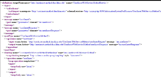
The structure of a WSDL based definition for ports is given in Figure 3.3. Figure 3.4 displays a sample WSDL source code that exhibits the abovementioned elements.
12
13
Figure 3.4: WDSL Sample
3.2.3 UDDI
UDDI is a database for web services. It is used as a container for web services description and web services addresses. It stores the service information on three page categories: White pages, yellow pages and green pages. White pages are used for the search of the companies that offer web services and their business area. Yellow pages are used for grouping the web services. And green pages are used for storing the technical information about web services. UDDI services of a company also record the services available within the company and thus the services can be opened to the use of the whole world. Although UDDI was developed by Oasis, it is also supported by many large IT firm. The communication between different UDDI servers is also carried out using the SOAP protocol.
14 3.3 Is Web Service Just Sharing Data?
In order to understand the logic behind web services clearly, the relation of web services and data sharing has to be clarified. For this purpose, consider an enterprise operating in the production sector. The enterprise has several dealers that give orders for production. The orders are processed by the operators manually, and they are entered into the enterprise computer system. These orders have to be tracked by the computer system in subsequent steps. However, this approach is slow due to the manual nature and error prone. Furthermore, the dealers can only be notified after the orders are successfully entered into the system which may bring latency. On the other hand, use of web services for order entry would allow dealers to enter their orders directly using their own system. Such an approach would reduce the processing time and possibility of error. So, it is evident that web services are not useful for data sharing only, but, they also help increase productivity and reduce errors. Those effects can be seen more clearly in the case of collaborations where more than two enterprises are involved. For example, in stock market ordering systems, many companies communicate via web services where each one may have its own system on a different platform.
3.4. Advantages of Using Web Services
Even though there are many languages for programming and many platforms to be used as application servers, all of them support the web services standards. Hence, web services can be deployed in a platform independent manner for interoperation of different systems. So, application methods or functions can be accessed on internet. Moreover, web services allow a more secure communication over the simple HTTP protocol. In summary, web services increase productivity and reduce the development and integration costs.
15
Chapter 4
Overview of Information Systems
The role of information systems in the transformation of businesses for obtaining a more competitive state is frequently mentioned in recent times. Many companies have information systems in their body. Silver defines information system as follows:
“Information systems are implemented within an organization for the purpose of improving the effectiveness and efficiency of that organization. Capabilities of the information system and characteristics of the organization, its work system, its people and its development and implementation methodologies together determine the extent to which that purpose is achieved.”[12]
In an information system, hardware and software work together, and it is only complete with people and organizations that collect, filter, process, create and distribute data. Information systems act as a bridge between the business lines and information technology. The theoretical infrastructure of information and computation technology is used to study various business models and related algorithmic processes within a computer science discipline. [13], [14] There are many types of information system. In 1980s, information systems were defined as a pyramid like structure (Figure 4.1) where transaction processing systems are at the bottom of the pyramid, followed by management information systems, decision support systems and executive information systems being at the top. [15]
16
Figure 4.1: Four Level Pyramid Model
This model is very useful and it has been a pioneer that has been followed by new categories of information systems. Nowadays, the main groups of information systems can be categorized as follows:
Data warehouses
Enterprise Resource Planning systems
Enterprise Systems
Expert Systems
17
Chapter 5
SOA Based Information System for Diseases
In the previous chapters, SOA and the underlying technology are explained. This chapter will investigate the analysis and design of a SOA based information system for diseases. The health sector as an ecosystem includes patients, doctors, hospitals, pharmacies, suppliers, insurance companies, and last but not least government bodies responsible for health related issues. There are unfortunately no standards about health records of patients. Important unsolved issues such as privacy and security have prevented the development of standards; therefore there are no integrated information systems. Patient’s data are stored and processed in enterprise systems that do not communicate. This causes an extra work load when a patient visits different institutions where the patient has to display documents such as test results, reports etc. The aim of this thesis is to develop a SOA based information system that can handle the integration of health records. This system may be used by all doctors (and other parties) to enter patient information for controlled access by other parties. A user friendly, web services based online system can also be extended to a mobile application that would allow greater mobility. In the following sections, the analysis and design of this system will be explained.
5.1. Analysis Using UML
UML (Unified Modeling Language) is a standard for the modeling of real-world objects as a first step in object-oriented design methodology. It is used to specify, visualize, modify, construct and document the artifacts of an object-oriented, software intensive system under development. Two major types of UML diagrams can be used: Structural UML diagrams and behavioral UML diagrams. Figure 5.1
18
displays the hierarchy of UML diagrams that will constitute the building blocks of the model.
Figure 5.1: UML Diagrams
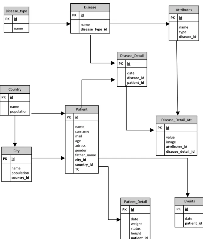
In the following sections, use-case diagrams, class diagrams and sequence diagrams will be utilized for the analysis of the project. The first step in the analysis is to collect the requirements for the system. The outcome of this step is the conceptual data model for the system, i.e. the ER (Entity Relationship) diagram, that contains the tables and the corresponding columns to be used.
5.1.1. The ER Diagram of the System
The conceptual data model is given in Figure 5.2 where all tables and columns are displayed. A relational approach is preferred for the design so that transactions can be carried out effectively.
19 Disease PK id name disease_type_id Attributes PK id name type disease_id Disease_Detail PK id date disease_id patient_id Disease_Detail_Att PK id value image attributes_id disease_detail_id Country PK id name population City PK id name population country_id Patient PK id name surname mail age adress gender father_name city_id country_id TC Patient_Detail PK id date weight status height patient_id Events PK id date patient_id Disease_type PK id name
20
5.1.2. General overview of the system with UML
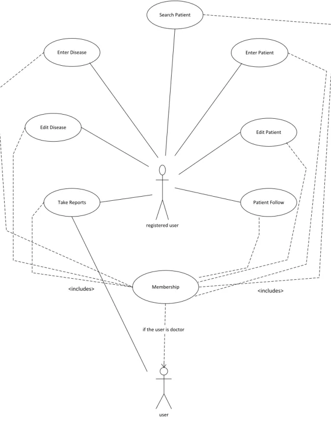
The essential functions to be performed in the information system are documented in Figure 5.3 where the user role “doctor” has the greatest focus. Following this, Figure 5.4 includes the use case for the general overview: all actors (user types) and all functions are mapped to each other in this use case diagram. In the following sections, the use cases of Figure 5.4 are explained in detail as a scenario. The coding of the system is essentially based on that scenario of work flow.
21 registered user Enter Disease Search Patient Enter Patient Edit Disease Edit Patient
Take Reports Patient Follow
Membership
user if the user is doctor
<includes> <includes>
22
5.1.3. Use Case Diagrams with scenarios
Use Case:
General OverviewSystem register user(doctor) user system admin To be membership Login System Search Patient Enter Patient Enter Disease Membership Checking Edit Patient Reporting Edit Disease Patient Follow Manage Security
23
Use Case:
Login SystemPrimary Actor: User
Stakeholders and Interests:
User: Wants to enter system quickly and does not want to encounter any errors. System: To allow the user for entry into the system without any errors.
Preconditions: The user must be a registered doctor in the system. Success Guarantee (Post conditions):
User enters the system successfully and performs operations. Main Success Scenario (or Basic Flow):
1. Open the browser in the computer which has the internet connection. 2. Enter the “URL” to the browser.
3. Go to the website. 4. Click the Login button. 5. Enter the user name 6. Enter the password. 7. Click the “Login” button.
Extensions (or Alternative Flows) *a. At any time, System fails.
To support recovery and correct working, ensure all transaction sensitive state and events can be recovered from any step of the scenario.
1 a. The computer lost the internet connection.
1. Use another computer which has the internet connection. 1 b. Computer may be faulty.
24
1 c. Computer has not any internet browser.
1. Use another computer which has the internet browser. 2 a. The browser may be corrupted.
1. Use another computer which has a working browser. 2 b. Enter the invalid URL.
1. Browser gives the error message. 2. User enters the URL correctly. 3 a. The web site can be collapsed.
1. The user notifies the system administrator about the site. 4 a. Login button does not work.
1. The user notifies the system administrator about this error. 5 a. Validation error.
1 . User enters the user name correctly. 6 a. Enter the password wrong.
1. User enters the password correctly. 7 a. “Enter” button does not work.
1. The user notifies the system administrator about this error. Special Requirements
Computer
Internet connection
Username
25
Use Case Diagram:
Login SystemFigure 5.5: Use Case Diagram of the Login System
Use Case:
To Be MembershipPrimary Key: User
Stakeholders and Interests:
User: Wants to login to the system and enter the values fast and correctly, does not want to see any systematic problems.
System Admin: Wants to get correct variables and give approval quickly. System: Wants to give correct password to the user using correct algorithms. Preconditions: The user must be a doctor.
26
Success Guarantee (Post conditions): User inserts the correct values to the system and logins the system with password coming from system.
Main Success Scenario (or Basic Flow):
1. Open the browser in computer which has the internet connection. 2. Enter the “URL” to the browser.
3. Go to the website.
4. Click the “Register” button. 5. Fill the empty fields.
6. Click the “OK” button.
7. Get the “Confirmation Message” from the system. 8. System admin gives approval for the password. 9. Get the password.
10. Login the system with password and username. Extensions (or Alternative Flows)
*a. At any time, System fails. To support recovery and correct working, ensure all transaction sensitive state and events can be recovered from any step of the scenario. 1-6 same as in the “Login” use case
7 a. Does not get the confirmation message. 1-8 The user is not a doctor.
8 a. System admin does not give approval. 9 a. The passwords do not arrive.
1. The user notifies the system administrator about the password error. 10 a. Enter invalid information.
1. User enters the information correctly. Special Requirements
Computer
Internet connection
To be a doctor for registration
27
Use Case Diagram:
To Be MembershipTo be Membership Information Entry Membership Approval Registration information Send Password user(doctor) system admin system
28
Use Case:
Enter PatientPrimary Key: User
Stakeholders and Interests:
User: Wants to enter the information fast and correctly System: Wants to get the information fast and correctly. Preconditions: User must be a doctor.
Success Guarantee (Post conditions):
The information recorded in the system without any errors. Main Success Scenario (or Basic Flow):
1. Open the browser in computer which has the internet connection. 2. Enter the “URL” to the browser.
3. Go to the website. 4. Login the system
5. Click the Add patient button. 6. Fill the blank fields on the screen 7. Click the Save button.
Extensions (or Alternative Flows): *a. At any time, System fails.
To support recovery and correct working, ensure all transaction sensitive state and events can be recovered from any step of the scenario.
1-6 same as in the “Login” use case Special Requirements:
Computer
Internet
To be a doctor
29
Use Case Diagram:
Enter PatientEnter Patient
Information Entry
Add Record user(doctor)
system
Figure 5.7: Use Case Diagram of the Enter Patient
Use Case:
Edit PatientPrimary Key: User
Stakeholders and Interests
User: Wants to enter the information fast and correctly. System: Wants to get the information fast and correctly. Preconditions: User must be a doctor.
30 Success Guarantee (Post conditions):
The information recorded in the system without any errors. Main Success Scenario (or Basic Flow):
1. Open the browser in computer which has the internet connection. 2. Enter the “URL” to the browser.
3. Go to the website. 4. Login the system
5. Click the Edit patient button. 6. Fill the blank fields on the screen 7. Click the Save button.
Extensions(or Alternative Flows): *a. At any time, System fails.
To support recovery and correct working, ensure all transaction sensitive state and events can be recovered from any step of the scenario.
1-6 same as in the “Login” use case Special Requirements
Computer
Internet
To be a doctor
31
Use Case Diagram:
Edit PatientEdit Patient
New Information Entry
Edit the Record user(doctor)
system
Figure 5.8: Use Case Diagram of the Edit Patient
Use Case:
Search PatientPrimary Actor: User Stakeholders and Interests:
User: Wants to get result fast and correctly.
System: Finds the true result fast and returns the data without any problem. Preconditions: User must be a doctor.
Success Guarantee (Post conditions):
32 Main Success Scenario (or Basic Flow):
1. Open the browser in computer which has the internet connection. 2. Enter the “URL” to the browser.
3. Go to the website. 4. Login the system
5. Click the “Person Search” button. 6. Enter the word to search.
7. Click the search button.
8. System returns the result. If there are no results, the system gives warning. Extensions (or Alternative Flows):
*a. At any time, System fails.
To support recovery and correct working, ensure all transaction sensitive state and events can be recovered from any step of the scenario.
1-6 same as in the “Login” use case
7 a. System does not connect to the database.
7 b. System retrieves the wrong information from the database. Special Requirements
Computer
Internet
To be a doctor
33
Use Case Diagram:
Search PatientSearch Patient
Word Entry Searching Give Result user(doctor) systemFigure 5.9: Use Case Diagram of the Search Patient
Use Case:
Enter DiseasePrimary Key: User
Stakeholders and Interests
User: Wants to enter the information fast and correctly. System: Wants to get the information fast and correctly. Preconditions: User must be a doctor.
34 Success Guarantee (Post conditions):
The information recorded in the system without any errors. Main Success Scenario (or Basic Flow):
1. Open the browser in computer which has the internet connection. 2. Enter the “URL” to the browser.
3. Go to the website. 4. Login the system
5. Click the Add Disease button. 6. Fill the blank fields on the screen 7. Click the Save button.
Extensions (or Alternative Flows): *a. At any time, System fails.
To support recovery and correct working, ensure all transaction sensitive state and events can be recovered from any step of the scenario.
1-6 same as in the “Login” use case Special Requirements
Computer
Internet
To be a doctor
35
Use Case Diagram:
Enter DiseaseEnter Disease
Information Entry Add Record user(doctor) system36
Use Case:
Edit DiseasePrimary Key: User
Stakeholders and Interests
User: Wants to enter the information fast and correctly. System: Wants to get the information fast and correctly. Preconditions: User must be a doctor.
Success Guarantee (Post conditions)
The information recorded in the system without any errors. Main Success Scenario (or Basic Flow)
1. Open the browser in computer which has the internet connection. 2. Enter the “URL” to the browser.
3. Go to the website. 4. Login the system
5. Click the EDIT DISEASE button. 6. Fill the blank fields on the screen 7. Click the Save button.
Extensions (or Alternative Flows): *a. At any time, System fails.
To support recovery and correct working, ensure all transaction sensitive state and events can be recovered from any step of the scenario.
1-6 same as in the “Login” use case Special Requirements
Computer
Internet
To be a doctor
37
Use Case Diagram:
Edit DiseaseEdit Disease
New Information Entry
Edit the Record user(doctor)
system
Figure 5.11: Use Case Diagram of the Edit Disease
Use Case:
ReportingPrimary Key: User
Stakeholders and Interests:
User: Want to take true results and see the understandable values. System: Want to give the results fast and correctly.
Preconditions: -
Success Guarantee (Post conditions):
38 Main Success Scenario (or Basic Flow):
1. Open the browser in computer which has the internet connection. 2. Enter the “URL” to the browser.
3. Go to the website. 4. Click the reports button
5. Select the values for parameters. 6. Click the Ok Button.
7. Get the results in the table. Extensions(or Alternative Flows): *a. At any time, System fails.
To support recovery and correct working, ensure all transaction sensitive state and events can be recovered from any step of the scenario.
1-6 same as in the “Login” use case
7 a. The system displays incorrect values.
1. The user notifies the system administrator about the site. Special Requirements:
Computer
Internet
To be a doctor
39
Use Case Diagram:
ReportingReporting
Information Entry
Give Information user
system
40 user
Country Analysis of Disease Gender Analysis of Disease
Year Analysis of Disease
Region Analysis of Disease
Type Analysis of Disease Age Analysis of Disease
Report OverView
41
5.1.4. Class Diagrams
Class Diagram:
To Be MembershipBased on the use cases described in the previous section, software classes managing the functions have to be realized. Figure 5.14 to Figure 5.18 display the class diagrams that represent the methods for the corresponding use case.
+userInsert() : Boolean -name:String -surname:String -mail:String -userId:int -password:int -hospitalName:String -major:String -phone:String -authority:String userInsertWebServiceMethod
42
Class Diagram:
Login the System+thssLogin() : String -userId:int -password:int
loginWebServiceMethod
43
Class Diagram:
Add Patient+patientInsert() : Boolean -name:String -surname:String -mail:String -age:int -address:String -gender:String -tc:String -country_id:String -city_id:String patientInsertWebServiceMethod
Figure 5.16: Class Diagram of the Add Patient
44
Class Diagram:
Edit Patient+patientEdit() : Boolean -mail:String -address:String -country_id:int -city_id:int -weight:int -height:int patientEditWebServiceMethod
45
Class Diagram:
Reports+report() : Integer -country_id:int -city_id:int -gender:char -year:int -age:int -type_of_disease:string ReportWebServiceMethod
46
5.1.5. Sequence Diagram
Finally, Figure 5.19 displays the system sequence diagram that models how the different actions are related to each.
:Admin
:Doctor (system user)
Add
Disease DiseaseEdit
Register Login
Add Patient Edit Patient
Reporting News ui(n,s,m,uid,pss,hna,m,p,au) userInsert() Lm(u,p) userLogin() Lm(u,p) userLogin() diseaseInsert(dis_type,dis_nm,att_nm,att_value) diseaseInsert() diseaseEdit(dis_att_nm,att_value) diseaseEdit()
sent news request
get news response
reportType(c_id,ct_id,g,y,a,typeofdis) getreport() patientInsert(n,s,m,a,g,c_id,ct_id) patientInsert() patientEdit(m,ad,c_id,ct_id,wght,hght) patientEdit() patientInsert(n,s,m,a,g,c_id,ct_id) patientInsert() patientEdit(m,ad,c_id,ct_id,wght,hght) patientEdit() reportType(c_id,ct_id,g,y,a,typeofdis) getreport()
Figure 5.19: Sequence Diagram of the System
5.2. General Overview of the SCIENCE
SCIENCE is the “brand name” of the system developed within this thesis. SCIENCE consists of two parts, first one is the web based part and the second part is the mobile application. The web based part is developed using Java, Jsp and Jquery technologies and the mobile part is developed using the Android technology. Both systems use a
47
common database implemented in SQL Server. These technologies have been preferred because it is relatively easy to write and apply web services in this technology. Also, finding documents and getting support is very effortless. There are lots of frameworks and components which facilitate the work in this technology. SCIENCE is a system that performs the scenarios described in the use cases. Some example screenshots of the system can be seen in the following pages where the flow of the execution starts with the login of the user (admin or doctor) and continues with features such as adding/editing a disease by the admin user, and adding/editing a patient by the doctor.
5.2.1 Overview of the SCIENCE system’s web based part
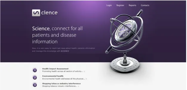
Figure 5.20: Main Page of Science
Figure 5.20 displays the main page of Science system. We can see that all users can reach the news and reports.
48
Figure 5.21: Login Page of Science
For Login to the system, user can enter his/her user name and password as can be seen in Figure 5.21. Then registration information can be entered as shown in Figure 5.22.
49
Figure 5.23: Admin Home Page of Science
There are two types of registered users in this system. First one is the admin user and the other one is the normal user. Only the admin users have Add Disease and Edit Disease privileges (Figure 5.23).
Figure 5.24: User Home Page of Science
It can be observed in Figure 5.24 that normal users do not have the privileges for Add Disease and Edit Disease. These users can only access to “Add Patient” and “Edit Patient” functionalities.
50
Figure 5.25: Search Patient Page of Science
When the user wants to add a patient, he/she can search the name of this patient according to the patient’s national identification number. If the search does not return any data, the user continues adding the patient with “Add Patient without Search” option (Figure 5.25).
51
Figure 5.27: Add Patient Result Page of Science
If the addition process finishes successfully (Figure 5.27), the user continues with “Add Detail for Patient” option (Figure 5.28).
52
Figure 5.29: Add Disease Page of Science
If the admin wants to add a new disease to the system, “Add Disease Name” option and “Add Disease Attribute” option have to be used (Figure 5.29). If the admin selects “Add Disease Name” option, firstly he/she selects disease type and then enters the disease name (Figure 5.30).
53
Figure 5.31: Add Disease Name Result Page of Science
If the disease is added successfully (Figure 5.31), the admin continues adding disease attributes using “Add Attribute for Disease” option. Meanwhile, a disease can also be associated with a type as in Figure 5.32.
54
The admin can also edit disease information as shown in Figures 5.33 and Figure 5.34.
Figure 5.33: Edit Disease Page 1 of Science
55
Once transactional operations are carried out, users can also access reports that have a predefined query structure. There are 3 options for displaying reports. These are “Reports by years”, “Reports by gender”, and “Reports by age” (Figure 5.35).
Figure 5.35: Reports Page 1 of Science
In “Reports by year” option, the user can base the reports on disease type or disease name (Figure 5.36). Figure 5.37 and Figure 5.38 exhibit a report where the occurrence of a certain disease is displayed for the selected period of time.
56
Figure 5.37: Reports Page 3 of Science
57
Similarly for the “Reports by gender” option, the user can take reports based on “disease type” or “disease name” as shown in Figures 5.39, 5.40, and 5.41.
Figure 5.39: Reports Page 5 of Science
58
Figure 5.41: Reports Page 7 of Science
Finally, Figure 5.42 shows the sign out page for the system. Even though the patient and disease related pages of the system require login of the user, news about diseases and announcements can be browsed directly through the main page without login (Figure 5.43).
59
Figure 5.43: News Page of Science
5.2.2 Overview of the SCIENCE system’s mobile based part
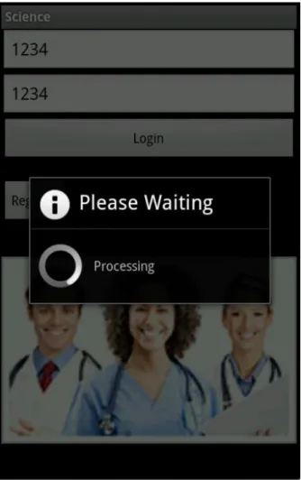
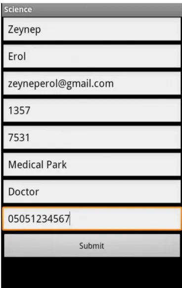
Science system has a mobile application developed for Android systems. The flow of execution is similar to the flow of the web based part. Figures 5.44 to Figure 5.55 display the screenshots of the “Mobile Science” that exhibit a flow from login to sign out. For example Figures 5.44 and 5.45 are used for login, and Figure 5.46 displays the registration screen with the necessary fields to be supplied by the user.
60
61
62
63
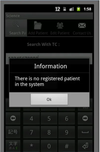
Once a doctor is successfully registered and the doctor has logged in as a user, patient search can be carried out using the “Search Patient” tab as shown in Figure 5.47. The existence of the patient searched is given as a response in Figure 5.48.
64
65
Figure 5.49: Add Patient Page 1 of Mobile Science
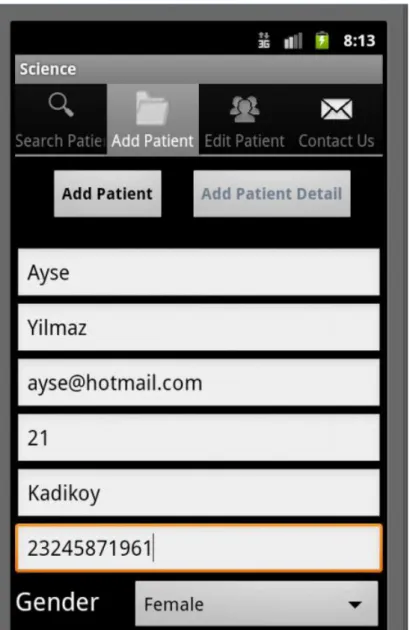
The user can add patients and the corresponding details using the tabs Add Patient and Add Patient Detail as in Figures 5.49 to Figure 5.51.
66
67
68
Figure 5.52: Edit Patient Page 1 of Mobile Science
Once a patient is recorded its details can be edited after the patient is searched based on his/her identification number as shown in Figures 5.52 to Figure 5.54.
69
70
71
Figure 5.55: Contact Page of Mobile Science
The user can also send e-mails to the system for supplying feedback using the “Contact Us” tab (Figure 5.55).
72
Chapter 6
Conclusion
The main objective of the thesis is the design of an information system for patient’s diseases that can be accessed using web browsers and mobile devices. A SOA based approach using web services has been implemented to reach that goal. The modelling is based on UML and basic user requirements have been translated into objects and classes implemented in Java language. The design is aimed to be flexible and extendable so that new modules can be added in the future. The theoretical analysis is supported by the practical applications that are developed for maximum user friendly operation. The reporting capabilities of the system can be extended to include more detailed information supply about epidemics based on time and/or location. Furthermore, the system can be extended to include patient’s measurements such as blood pressure or heart rate. For this purpose mobile devices can be integrated to the system that sends the measurement values via wireless networks.
73
References
[1] J. Matkovic, K.Fertalj, “Comparative analysis of Web Services and Web
Service Development technologies”,MIPRO2010,May 24-28 2010,Opatija, Crotia
[2] Baoan Li,“Research and Application of SOA Standards in the Integration on
Web Services”, 2010 Second International Workshop on Education Technology
and Computer Science.
[3] R. William Mavle, William C. Lewis “Risk Management Framework for
Service-Oriented Architecture”, 2009 IEEE International Conference on Web
Services
[4] Hongman Wang, Wangxin Zhang, Yi Ge, Shuai Liang, “Service Information
Management Framework based on SOA” IC-BNMT 2010.
[5] FedaAlShahwan, Klaus Moessner, “Providing SOAP Web Services and
RESTful Web Services from Mobile Hosts”, 2010 fifth International Conference on
Internet and Web Applications and Services. [6] http://www.soa-consortium.org/
[7] Amit Sinha, Fillmore Bowen, “SOA Concortium Promoting Business-Driven
SOA “Executive Suite SOA” Case Study Summary” June 28, 2007.
[8] http://en.wikipedia.org/wiki/Web_service
[9] Jingyu Zhang, David Levy, Shiping Chen, John Zic, “mBOSSS+: A Mobile
Web Services Framework”, 2010 IEEE Asia-Pasific Services Computing
74
[10] Dhiah Al-Shammary, Ibrahim Khalil, LoayE.George, “Clustering SOAP Web
Services on Internet Computing Using Fast Fractals”, 2011 IEEE International
Symposium on Network Computing and Applications.
[11] Dhiah Al-Shammary, Ibrahim Khalil, “SOAP Web Service Compression
Using Variable and Fixed Length Coding”, 2010 Ninth IEEE International
Symposium on Network Computing and Applications. [12] http://en.wikipedia.org/wiki/Information_system
[13] M. Monheit, A. Trafrir, “Information System Architecture: A Consulting
Methodology”,
[14] J. A. Zachman,“A framework for information systems architecture”, IBM Systems Journal Vol: 26, No:3 , 1987, 1999
[15] Kathleen A. Moser, Daniel J. Mazzola, Robert T. Keim, Andrew S. Philippakis, “Modelling The Information System Architecture: An Object Oriented
75
Curriculum Vitae
Zeynep Erol was born on 01 April 1985, in Istanbul. She received her BS degree in Computer Engineering in 2009 from Kadir Has University. She has been working as a Java Developer at Bizim Menkul Değerler since 2011. During her graduate education, she has been affiliated with web services and mobile technology. Her research interests include entrepreneurship, human computer interaction and java technologies.