©
2011
Nature
America,
Inc
. All rights reserved.
IntroDuctIon
Biological cells have developed a complex, truly nanoscale infra-structure for transport, biochemical synthesis, information processing, sensing and other life-sustaining molecular activities1–3. Nanotubular structures are quite common in biological systems, in particular for establishing cell-to-cell connections4. Intercellular nanotubes (ICNs) formed from filopodial structures or after separa-tion of tight cell-cell contacts mediate transport processes between cells. For example, diffusion of inositol triphosphate through nano-tubes possibly mediates calcium signaling between macrophages, a gradient of membrane tension can induce transport of membrane patches and surface proteins, and molecular motors can transport organelles along filamentous actin in ICNs5–7. Land plants have developed plasmodesmata, a form of sophisticated membrane channel used to span the rigid cell walls to mediate the cell-to-cell exchange of signaling molecules8.
It remains a challenging engineering task to model, design and build artificial devices that precisely probe, interface, imitate or even augment chemical or physical key features of biological systems9–13. Nanotube-vesicle networks (NVNs) are versatile, man-made soft-matter constructs of micrometer and nanometer dimensions that can, in this context, serve as models for interlinked biochemical reactors14,15, which are closely related to naturally occurring ICN nanotube assemblies3. The networks are fabricated from individual phospholipid molecules by a combination of self-organization processes, which lead to spherical bilayer membrane compartments, and subsequent forced shape transition operations, which transform selected membrane regions into nanotubes and new liposomes. The networks are useful as spatially separated, yet interconnected, chemical reactors of differentiated contents, allow-ing the study of membrane proteins and (bio)chemical reactions on biologically relevant size scales16,17.
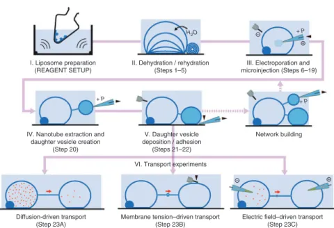
The protocol described here is schematically illustrated in Figure 1. It combines a preparation procedure for giant unilamellar vesicles (GUVs) connected to multilamellar membrane reservoirs with electroporation and microinjection methods for the extraction of lipid nanotubes, the growth of new vesicles and their controlled surface adhesion. To create, investigate and apply vesicle-nanotube networks for transport and chemical reactions, these methods have been unified and integrated with a variety of microscopy setups, such as differential interference contrast, wide-field laser-induced fluorescence and confocal microscopy15.
The network fabrication is based on generation of GUVs from phospholipids. An important requirement is the coexistence of unilamellar and multilamellar vesicles (MLVs), as the process of ‘daughter’ vesicle creation requires a continuous supply of membrane material. Few of the numerous liposome preparation methods18 are appropriate for this purpose. A modified procedure by Criado and Keller19, starting from a purified lipid extract of soybean material, has proven to be the most suitable20. This dehydration/rehydration procedure involves the deposition of a lipid film by evaporation of an organic solvent in a rotating flask; this is followed by brief ultrasonication and swelling of the resulting lipid film in phosphate buffer (Fig. 1, stage I). The liposome preparation is then dehydrated in vacuo, and subsequently rehydrated to form GUVs with attached multilamellar reservoirs (Fig. 1, stage II).
These soft-material structures, when immobilized on thin trans-parent slides, can be subjected to investigation and manipulation under a microscope20. Giant unilamellar phospholipid vesicles are tens of micrometers in diameter and harbor picoliters to femtoliters of internal volume21,22. The soft character of the lipid bilayer allows penetration with microneedles after membrane pore opening by electric fields (Fig. 1, stage III). Microinjection with glass capillaries
Generation of phospholipid vesicle-nanotube
networks and transport of molecules therein
Aldo Jesorka
1, Natalia Stepanyants
1, Haijiang Zhang
1, Bahanur Ortmen
2, Bodil Hakonen
1& Owe Orwar
11Department of Chemical and Biological Engineering, Chalmers University of Technology, Göteborg, Sweden. 2Department of Molecular Biology & Genetics,
Bilkent University, Ankara, Turkey. Correspondence should be addressed to O.O. ([email protected]). Published online 19 May 2011; doi:10.1038/nprot.2011.321
We describe micromanipulation and microinjection procedures for the fabrication of soft-matter networks consisting of lipid bilayer nanotubes and surface-immobilized vesicles. these biomimetic membrane systems feature unique structural flexibility and expandability and, unlike solid-state microfluidic and nanofluidic devices prepared by top-down fabrication, they allow network designs with dynamic control over individual containers and interconnecting conduits. the fabrication is founded on self-assembly of phospholipid molecules, followed by micromanipulation operations, such as membrane electroporation and microinjection, to effect shape transformations of the membrane and create a series of interconnected compartments. size and geometry of the network can be chosen according to its desired function. Membrane composition is controlled mainly during the self-assembly step, whereas the interior contents of individual containers is defined through a sequence of microneedle injections. networks cannot be fabricated with other currently available methods of giant unilamellar vesicle preparation (large unilamellar vesicle fusion or electroformation). Described in detail are also three transport modes, which are suitable for moving water-soluble or membrane-bound small molecules, polymers, Dna, proteins and nanoparticles within the networks. the fabrication protocol requires ~90 min, provided all necessary preparations are made in advance. the transport studies require an additional 60–120 min, depending on the transport regime.
©
2011
Nature
America,
Inc
. All rights reserved.
and the associated micromanipulation methods date back to almost a century23, and basic micropipette setups have remained almost unchanged in principle because of the sturdiness and simplicity of the technique24. Highly repeatable fabrication procedures and tools for microneedles became widely available just after the patch-clamp method for single-cell electrophysiology was developed25. A capillary pulling instrument is crucial for the generation of NVNs. Similarly, the electroporation method, originally established for direct delivery of genetic material26 or chemical compounds27,28 into the interior of biological cells, has central importance in network fabrication, as stable pores allow facile introduction of microneedles with quite large orifices into bilayer containers (electroinjection)20,29. Once a needle is inside a GUV, the bilayer tightly seals around the tip. The adhesion of the membrane is typically strong enough to allow the pulling of lipid material from the membrane, thereby instantly forming an open nanoconduit between the vesicle and the capillary. The flexible lipid nanotubes created in this way can be expanded at the needle-connected end by means of positive injection pressure, to an extent that a new vesicle is formed (Fig. 1, stage IV). Constant subsequent injection of fluid from the needle allows the ‘daughter’ vesicle to grow to a size appropriate for deposition onto the substrate (Fig. 1, stage V). Iteration of this pulling and vesicle- generation process enables the building of whole networks of interconnected containers, in which size, geometry and individual contents can be controlled. If a new needle with different internal solution is used for the generation of each new vesicle, a network with differentiated contents can be created. The composition of the internal volume of each newly created vesicle is determined by the size ratio of mother and daughter vesicles30.
As the nanoconduits are open on both ends and thus truly inter-connect the individual containers, exchange of internal solution, and chemical compounds dissolved therein, is possible. Different regimes of exchange of matter have been investigated by us. In particular, the transport of small molecules and nanoparticles by diffusion31–33, by membrane tension–driven (Marangoni) flow34 and through electro-phoretic migration35,36 were studied in detail (Fig. 1, stage VI).
Although diffusion and electrophoresis are rather common transport processes often encountered in the biosciences, the trans-port of material through nanotubes by tension-driven (Marangoni)
flow of the lipid membrane is a noteworthy specialty that has been investigated in greater detail37. A flow of lipids is created along the tube membrane from the region of low membrane tension to a region of high membrane tension, which is temporarily created by pressing a vesicle with a carbon fiber. Material transport occurs through a plug flow induced in the tube by the flowing membrane. The membrane of an NVN is in the low-tension regime38, in which tension increases exponentially with area strain39. However, as the applied tension gradients are small, a series expansion around the initial tension gives a linear relation between tension and strain37.
Internalization of fluorescent compounds or labeled chemical entities in network-integrated vesicles as well as staining of the membranes by lipophilic fluorescent probes allow application of modern microscopy techniques to investigate a variety of aspects, such as membrane and transport dynamics40, biocatalysis31,41 and nanotube properties38,42. The biomimetic nature of the network has also opened pathways to the study of membrane proteins17 and the association of biological cells to networks43,44.
Objectives of this technique
Here we describe a thoroughly tested protocol for generating NVNs from commonly available materials and sources14,20, as well as for performing three different network internal transport operations31,32,34,35,37. Because of their micro- and nanoscale size and flexibility, networks are highly suitable for the construction of biomimetic chemical reactor models and for the study of the trans-port and interaction of chemical and biochemical reagents under conditions of close confinement. Models for intracellular reaction chains and biochemical kinetics, molecular crowding, functional aspects of artificial cells, ion channels and other membrane proteins are among the topics that can become more accessible to scientists, while allowing a high degree of integration with existing micro-scopy and micromanipulation systems.
Previous techniques and alternative methods
As NVNs are, in essence, combinations of nanofluidic devices45 and microreactors46, solid-state microfluidic and nanofluidic devices accommodate some of their functions and properties47–49. Cell blebbing50 is an alternative method by which to obtain unilamellar
I. Liposome preparation (REAGENT SETUP)
IV. Nanotube extraction and daughter vesicle creation
(Step 20)
Diffusion-driven transport (Step 23A)
Membrane tension–driven transport (Step 23B)
Electric field–driven transport (Step 23C) V. Daughter vesicle
deposition / adhesion (Steps 21–22)
Network building II. Dehydration / rehydration
(Steps 1–5)
H2O + P
+
III. Electroporation and microinjection (Steps 6–19)
VI. Transport experiments
+ P + P
–
– +
Figure 1 | Schematic overview over the network generation procedure. The procedure consists of five fundamental fabrication subprocedures and three subsequently possible transport experiments. The pink thread in the background of the scheme depicts the sequential order of the operations. Building of larger or topologically more advanced networks, depicted as an optional sub-procedure using dashed pink lines, involves repeated daughter vesicle creation and deposition. The images are illustrated as simplified, not-to-scale side views. Black triangles depict translation micromovements of needle or electrode, and red arrows symbolize the transport direction of network-internalized entities. Positive injection pressure is denoted by + P; electrode polarity is also indicated for the electroporation and field-driven transport operations. The procedure detailed in this protocol starts at stage II (de/rehydration) and uses two-vesicle assemblies as elementary network structures for transport experiments.
©
2011
Nature
America,
Inc
. All rights reserved.
membrane compartments with certain, albeit limited, functionality; it is useful, in particular, for the study of membrane proteins in their native environment17. Moreover, innovative biomimetic techniques for the study of membrane-related processes and biomolecular inter-actions associated with membranes have been developed51,52. Few of these techniques can provide the biocompatibility, structural flex-ibility and expandability that the individually designed soft-matter network infrastructures provide. A variety of alternative methods exist for the preparation of phospholipid vesicles of the type used in this protocol. MLVs can be conveniently prepared by a simple and robust film-hydration technique53 or by spray drying/lyophilization54 for larger-scale preparations. There is no reliable method to produce exclusively GUVs; the electroformation method reaches the highest yields55,56, especially when used in combination with spin coating of a lipid film57. Electroformation is limited to low ionic strength buffers, but methods to increase the ion strength have been developed58.
There are also alternative methods to produce lipid nano-tubes. Examples include streptavidin binding to biotinylated membranes59, pulling action of molecular motors60, and optical tweezers61. The tubes are generated, either by shape-transforming phospholipid vesicles or by applying point forces to vesicles or bio-logical cells, but such protrusions are typically not connected to other vesicles or cells. Moreover, the electroformation procedure has been found to spontaneously produce nanotubes between GUVs62,63. We are not aware of any equivalent method to create soft-matter networks from lipid membranes with controlled and individual design. Solid-state microfluidic and nanofluidic devices do not have the flexibility, dimensions or biomimetic properties of vesicle-nanotube networks.
Applications and limitations
Vesicle-nanotube networks are uniquely shapeable and have been functionalized and tailored to provide insights into microscale phenomena, such as local confinement of reactants and catalysts to initiate and follow the progress of enzymatic reactions16,31. Membrane protein integration was demonstrated64, as was the interconnection and interaction with biological cells and active surfaces17,43,44. Vesicle content control and differentiation30, as well as external control of the outside solution composition, provide a large variety of possible chemical environments, and dynamic sub-compartmentalization has opened pathways to more advanced artificial cell models65.
Single-molecule transport and spectroscopy have been reported66, and fundamental properties and the dynamics of lipid nano-tubes38,42,67, which have an important role in intercellular transport and communication5, have been investigated.
Limitations come partly from the properties of the soft-matter materials used to build these networks and partly from restrictions on experimental conditions. Lipids are, for example, biomaterials prone to oxidative damage on prolonged exposure to air68, and the experimental setup, essentially a ‘lab in a droplet’, suffers from evaporation loss and gradually increasing osmotic stress on the networks. Furthermore, it is not possible to reproducibly fabricate identical networks, nanotube lengths and vesicle diameters, and vesicle positions on the surface vary. However, the use of patterned surfaces in combination with specific adhesion strategies can be used to define vesicle locations more accurately69. Automated pro-cedures for network fabrication do not exist yet.
Introduction of chemical materials into networks is rather eas-ily achieved, but removal of products or unwanted components from the network is more challenging and has thus far barely been studied. Other limitations arise from the simple internal structure of vesicles and their networks, which is not comparable with the complex internal machinery of biological cells. Active flow con-trol within networks, which is very desirable, has been studied to some extent; however, open questions remain with respect to valve designs, function and stability70.
Experimental design
The network generation protocol is essentially a micromanipula-tion and microinjecmicromanipula-tion procedure that relies on techniques com-mon in cell electrophysiology, in vitro fertilization and microscopy. The flexibility of the soft-matter networks allow a broad variety of different experimental techniques to be applied to the study of the desired feature. Liposome preparation from soybean lipid extracts requires a minimum of laboratory hardware, including a rotary evaporator, ultrasonic bath and glassware. Chemicals and materials are largely inexpensive and available from com-mon sources. Attention has to be directed to acquisition of proper micromanipulation hardware, in particular, under the perspec-tive of successful integration into an existing microscopy system. Figure 2 shows our accordingly modified wide-field laser-induced fluorescence microscopy setup. In addition to the components of
a
CCD camera Pulse generator Micromanipulator 1 Micromanipulator 2 FemtoJet injection pump Syringe pump Optical microscope Image capture softwareb
Figure 2 | Optical differential interference contrast microscopy setup for nanotube-vesicle network fabrication. (a) Required components assembled on an optical table. (b) Detail of the microscope table, showing the arrangement of the coarse micromanipulator pair with mounted capillary needle/needle holder and carbon fiber microelectrode/microelectrode holder, as well as their electrical connector clamps.
©
2011
Nature
America,
Inc
. All rights reserved.
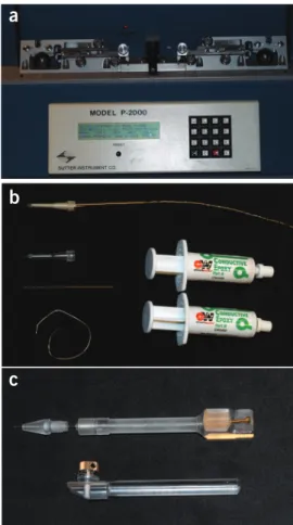
this setup, most importantly microscope, micromanipulators, pulse generator and injection pump, proper capillary fabrication and filling equipment is required, including a puller, a flame forger and means of backfilling pipette tips. Each commercial capillary puller has its own set of parameters to achieve a particular needle profile, taper and orifice diameter. Most manufacturers provide instruc-tions. Figure 3a shows our laser puller, displaying the simple one-line program that we created to obtain needles for the procedure described here. When creating new needle programs, we recom-mend confirming the resulting shape and dimensions, for example, by means of a scanning electron microscope.
Microelectrodes for electroporation and electrophoresis are eas-ily fabricated from raw wires or semi-manufactured commercial components such as plastic-encapsulated carbon fibers. The injec-tion needle holder, with its internal electrode and removable head, is an in-house development designed to fit the holding clamps of our particular micromanipulator model. All individual compo-nents are shown in Figures 3 and 4.
Surface coating of the substrate slides is recommended to ensure network stability over prolonged time periods. The preparation of coated (SU-8 photoresist) microscope cover slips is not strictly required, but provides the most suitable surfaces, which ensure reli-able repeatability of the experiments. Ordinary borosilicate or soda lime glass cover slips will give similar results, but suffer decreased longevity of the networks produced thereon. Coating the glass
cover slips with a thin (~5 nm) gold film is an alternative, which also helps to promote rapid adhesion of vesicles to the substrate. Gold-coated slides suffer from decreased optical transparency, and fluorescence quenching can occur close to the surface.
A clean-room facility with a spin coater and mask aligner is optimal, but effective SU-8 coating of microscope cover slips can be achieved under standard laboratory conditions with the help of a 2,000 r.p.m. bench-top spin coater, a 365-nm UV lamp and a hot plate.
Necessary experimental considerations for the microscopy part of the protocol are the type of microscope needed, e.g., bright-field differential interference contrast (DIC), confocal or fluorescence, the objective used and the imaging and data processing options. We use ×40 or ×63 objectives (Leica, HCX PL APO, ×40/×63, NA 1.25/1.32, oil immersed) for our confocal and wide-field laser-induced fluorescence microscopes. Both systems are placed on air-dampened optical tables, an essential measure to avoid vibration of the microneedles, and both feature optional manual or motorized translation tables. Available light sources/wavelengths define the possible selection of fluorescent labels to be used to visualize the networks. Reagents and dyes must be chosen accordingly. Image acquisition requires a color digital camera, as well as conveniently accessible and sufficiently powerful software to record and analyze its output.
a
b
c
Figure 3 | Capillary needle and carbon fiber microelectrode preparation.(a) Sutter Instruments P-2000 UV-laser capillary puller with a mounted needle, programmed for long-tapered needles with a ~250 nm opening. The parameters for this one-line program are as follows: Heat 430, FIL 4, VEL 50, DEL 240 and PUL 100. (b) Carbon fiber microelectrode (top) and the components needed to assemble it: plastic-encapsulated 5-µm (OD) carbon fiber, 5-cm-long (OD, 1 mm) glass capillary, 0.25-mm (OD) silver wire and two-component conductive silver epoxy. (c) Capillary (top) and microelectrode holder (bottom). The capillary holder body with FemtoJet tube–compatible thread is in-house built to fit the 8-mm micromanipulator mount. A fine-threaded screw at the rear end has a silver wire soldered to it, which runs inside the holder along the long axis and reaches into the capillary needle. The holder tip is a commercially available patch pipette grip head (Eppendorf). The microelectrode holder is from Narishige.
Figure 4 | Electrophoresis electrode assemblies, each consisting of a 1-mm (OD) hydrophobized capillary needle with cross-linked polyacrylamide gel plug and internal Ag/AgCl electrode. The capillaries are sealed with silicone rubber and are stored immersed in electrolyte.
©
2011
Nature
America,
Inc
. All rights reserved.
Fine micromanipulators are best attached directly to the micro-scope, but can also be mounted onto the dampening table, e.g., by means of a magnetic base. The latter option tends to increase the effect of needle vibrations, greatly influenced by the dimensions of the base and height of the microscope stage above the table.
Depending on the size and complexity of the network to be fabricated with this procedure and the nature of study to be per-formed with it, the time required for a full experiment can be a few hours. In this case, droplet evaporation loss needs to be taken into consideration and the droplet be replenished with distilled water, either manually in intervals or in an automated fashion, with the help of a pump supplying pure water at a constant rate (typically approximately 50–100 µl every 30 min) through a thin polytetrafluoroethylene tube. The actual loss is best determined before an experiment, using a balance.
The protocol described here has been thoroughly tested only on soybean polar extract (SPE), but not on pure single lipids or entirely artificial lipid mixtures. If networks are to be prepared from those precursors, the initial lipid preparation step must be modified to yield appropriate mixtures of unilamellar and MLVs, which can then be used in network building. We have found that, when pure lipids are used instead of SPE, the addition of ~0.1% cholesterol is essential to obtain stable MLVs. Hydration/dehydration is still the only method available to obtain suitable mixtures of multilamellar
and giant unilamellar liposomes, and we have not yet established a network fabrication procedure for pure lipids. Factors affecting the yield of formation are the degree of bilayer separation, (influ-enced by temperature and glycerol content), the lipid composition and the ionic composition of the surrounding buffer. Negatively charged lipids such as phosphatidyl serines or ethanolamines are known to enhance separation of the lamellae. Relatively low ionic strength buffer (10–50 mM) and the absence of multivalent ions that interlink charged lipids can also be beneficial.
Desired lipophilic membrane constituents such as glycolipids, fluorescently tagged lipids, biotinylated or antibody-modified lipids, membrane proteins, small hydrophobic sensor molecules and poly-mers can be added as a minor fraction, typically below 5 mol%, to the liposome pre-preparation, without compromising the ability to form GUVs and networks69.
Biological cells have been used as lipid source for direct net-work generation, using the same order of steps as in the protocol described above, to maintain the natural membrane composition and preserve the orientation of embedded membrane proteins17. The injection of more viscous, gel-forming polymer solutions into networks for the purpose of flow control and subcompartmen-talization has also been reported65,70,71. The network preparation procedure remains essentially the same, although it requires wider needle openings and microfabricated functional substrates.
MaterIals REAGENTS
crItIcal All reagent solutions and distilled water must be filtered through
0.2-µm membrane filters (0.45 µm for nanoparticle suspensions) before use in the experiments. Reagents are American Chemical Society grade or of higher purity.
Lipid preparation
Soybean polar (lipid) extract (SPE; Avanti Polar Lipids,
product no. 541602C) crItIcal Use of other lipids than SPE requires adjustments of the preparation step.
Glycerol (Sigma, product no. G5516) Chloroform (Sigma, product no. 650498) Phosphate buffer solution
Potassium phosphate (98%; K3PO4, Sigma, product no. P5629) !cautIon
It is irritating to skin and also poses the risk of serious damage to eyes. Potassium dihydrogen phosphate (KH2PO4, VWR, product no. 26936.236)
Trizma (Sigma, product no. T1503) EDTA (Fluka, product no. 03609)
Magnesium sulfate (MgSO4·7H2O, Merck, product no. 1.05886)
Phosphoric acid (H3PO4, Sigma, product no. P5811) !cautIon It causes
burns. It also poses the risk of serious damage to eyes. crItIcal The PBS buffer cannot easily be exchanged by other buffer systems, such as HEPES, as phosphate ions were found to be important to promote self-assembly of the lipid vesicles during rehydration.
Polyacrylamide hydrogel
Acrylamide (98%; Fluka, product no. 01700; 99%; Sigma, product no. A3553) !cautIon It is toxic and possibly teratogenic. It is readily absorbed through skin. Wear appropriate safety gloves. Latex gloves do not offer sufficient protection.
N,N′-methylenebisacrylamide (98%; Fluka, product no. 66670; 99%; Fluka, product no. 66667) !cautIon It is hazardous.
Ammonium persulfate ((NH4)2S2O8, Aldrich, product no. 431532)
!cautIon It is an oxidizer. It may cause allergic skin reactions. N,N,N′,N′-tetramethylethylenediamine (TEMED; Sigma,
product no. T9281) !cautIon It is caustic and has an irritating smell; handle only under a fume hood.
• • • • • • • • • • • • •
Dye label solutions for injections and membrane staining Atto 488 (water-soluble acridine dye (λexc = 488 nm); Atto-Tec,
product no. AD488-21) crItIcal Atto 488 gives the best photobleaching performance, compared with cyan-green-fluorescent dyes, such as Fluorescein, Alexa Fluor 488 or Dylight 488.
DiD oil (1,1′-dioctadecyl-3,3,3′,3′-tetramethylindodicarbocyanine perchlorate, membrane-soluble carbocyanine dye (λexc = 644 nm);
Invitrogen, product no. D307)
Carboxylated latex beads (20 nm, yellow/green FluoSpheres, λexc = 505 nm;
Invitrogen, product no. F8787) !cautIon Fluorescent dyes can lead to various short- and long-term skin photosensitization and cell-damaging effects. Avoid contact.
Surface coating
Negative photoresist SU-8 2002 (Microchem, product no. Y111029)
!cautIon It contains cyclopentanone as solvent and is highly flammable. Electrophoresis electrode preparation
Hexamethyldisilazane (HMDS; Sigma, product no. 379212) !cautIon It is highly flammable and is harmful if inhaled, if it comes in contact with skin and if swallowed. It also causes burns.
Hexanes (Sigma, product no. 139386) !cautIon It is highly flammable and is harmful if swallowed. It is irritating to eyes, respiratory system and skin. Potassium chloride (KCl, Sigma, product no. P9333)
Silver wire (OD (outer diameter) 0.25 mm; Goodfellow, product no. AG005140)
Gold or platinum wire (OD 0.25 mm; Goodfellow, product no. AU005140 or PT005140)
REAGENT SETUP
PBS buffer preparation ●tIMInG 15 min Dissolve 0.151 g Trizma base, 1.592 g K3PO4, 1.021 g KH2PO4, 0.062 g MgSO4·7H2O and 0.0465 g EDTA in
250 ml distilled water. Adjust the pH with H3PO4 to 7.8. Store at 4 °C for a
maximum of 1 month, but warm to room temperature (~21 °C) before use. Liposome preparation ●tIMInG 18 h (once, lasts for multiple
experiments) Liposomes are created following a procedure by Cirado and Keller19, which yields GUVs attached to multilamellar membrane reservoirs.
The procedure is optimized for SPE, a natural plant lipid mixture. Artificially • • • • • • • • •
©
2011
Nature
America,
Inc
. All rights reserved.
created mixtures or individual lipids need modifications, in particular cholesterol addition, to give a comparable result.
Prepare a 100 mg ml − 1 lipid stock solution by dissolving 100 mg SPE in 1 ml
of chloroform. Transfer a 30-µl aliquot of the stock solution to a 10-ml round bottom flask and add 300 µl chloroform. Evaporate on a rotary
evaporator at 6–8 kPa vacuum and 80–100 r.p.m. for 5 h to remove the solvent and form a lipid film. Add 3 ml of buffer and allow the lipid film to rehydrate for 12 h at 4 °C in a refrigerator. Add 30 µl glycerol to the suspen-sion and sonicate for 5–10 min in an ultrasonic bath. Partition 150-µl aliquots into 20 Eppendorf tubes (0.5 ml) and store at − 18 °C for a maximum of 6 months. crItIcal All manipulations of lipid solutions should be performed using thoroughly cleaned glassware. Do not use flasks, containers, syringes or pipettes made from plastics. crItIcal If it is desired to fluorescently label the whole liposome preparation, for example, to visualize the liposome membrane in every experiment, add 1–2 µl DiD oil directly into the lipid solution in chloroform. Otherwise, prepare membrane staining stock solution to use in individual experiments for membrane labeling.
Membrane staining dye solution and nanoparticle suspension preparation ●tIMInG 30 min First, dissolve 1 mg of DiD (oil) membrane staining dye in 1 ml fresh, anhydrous DMSO to obtain a membrane staining stock solution. Store dye stock solutions at − 18 °C under light exclusion for a maximum of 6 months. Second, dilute 25 µl of fluorescent carboxylated latex nanosphere suspension (FluoSpheres; yellow/green fluorescent latex beads, diameter 20 nm) in 1 ml buffer. Pass this particle injection suspension slowly through a 0.45-µm membrane syringe filter. This injection suspension is ready for backfilling and can be stored for up to 1 month at 2 °C under light exclusion, before particle aggregation interferes. Instead of nanoparticle suspensions, water-soluble fluorescent dye solutions can be injected into liposomes. A larger variety of absorption wavelengths is available for fluorescent dyes than for nanospheres. To prepare a dye solution with absorption/emission properties comparable with the FluoSpheres, dissolve 1 mg of water-soluble fluorescent dye, such as Atto 488 (λexc = 488 nm, M = 804 g mol
− 1, ε max =
90,000 M − 1 cm − 1), in 1 ml buffer to obtain an injection dye stock solution.
Pass the injection dye stock solution slowly through a 0.2-µm membrane syringe filter. The solution can be stored for several months at − 18 °C under light exclusion.
EQUIPMENT Lipid preparation
Rotary evaporator (Büchi R-144) Vacuum desiccator
Ultrasonic bath Glass pipette preparation
Capillary borosilicate glass tubes (OD 1 mm, ID (inner diameter) 0.78 mm, with filament; Harvard apparatus, product no. 300038)
Capillary puller (Sutter Instrument, model no. P-2000) Heat filament forger (Narishige, MF-900)
Surface fabrication
Microscope cover slips no. 1 (borosilicate glass, 25 mm × 50 mm, 0.15 mm thickness; VWR, cat. no. 631-0146)
Spin coater (2,000–3,000 r.p.m.; Laurell WS-400-6NPP-LITE/IND spinner, Laurell)
UV lamp (365 nm, 6 mW cm − 2)
Hot plate
Carbon fiber electrodes Glass cutter
Plastic-encapsulated carbon fibers (OD 5 µm; Dagan, ProCFE) Electrically conductive epoxy (ELFA, product no. 80-867-12) Silicone rubber
Microscopy
Optical microscope setup with DIC optics (Leica DM IRB, Leica)
crItIcal The arrangement of the micromanipulation and microscopy
components into a complete experimental setup is shown in Figure 2a. Figure 2b is the detail of the microscope table that shows the positioning of the injection needle in its holder and the counter electrode toward each other.
Wide-field illumination setup with laser (Spectra-Physics 2017) or fluorescence lamp
Filter/dichroic mirror set for λexc = 488 / λem = 525 nm (ref. 66)
• • • • • • • • • • • • • • • • •
An objective with ×40 or ×63 magnification (×40/×63, NA 1.25/1.32, oil immersed; HCX PL APO, Leica); ×40 magnification is optimal for most experiments
Confocal microscope (Leica DM IRE2 with TCS SP2 scanner, Leica) with laser excitation sources for λexc = 488/495 nm and 633 nm
Micromanipulation and microinjection
Two water-hydraulic micromanipulators (coarse/fine; Narishige MC-35A/ MHW-3, Narishige)
Polycarbonate capillary holder with internal electrode and patch pipette grip head (Eppendorf, cat. no. 920007414)
Two polycarbonate electrode holders (Narishige H-7, Narishige) Rectangular pulse generator (0–99 V), with adjustable pulse length and width between 1 and 2,000 ms (Digitimer DS2A, Digitimer)
Femtoliter automatic injection pump (Eppendorf FemtoJet, Eppendorf)Automatic micropipette (20–200 µl) with Eppendorf microloader tips (Eppendorf, order no. 5242 956.003)
Disposable syringes (5 ml; VWR, product no. 613-3951)PVDF membrane syringe filters (0.2 µm; VWR, product no. 514-4014)
Polytetrafluoroethylene filters (0.45 µm; VWR, product no. 514-4003)
!cautIon To keep the membrane soft, membrane syringe filters often contain small amounts of poly(ethylene glycol), which is gradually being washed out when the syringe filter is used. The network fabrication protocol is not known to be influenced by this additive. Membrane filters should be washed with distilled water before use, if contamination is expected to be an issue.
Optional
Syringe pump with plastic tubing, with ID 0.4 mm, for replenishment of evaporated buffer (Syringe pump NE-500 OEM)
Electromigration and electrode fabrication Power supply (0–6 V; ELFA Agilent U8002A, Agilent) Image analysis and processing
Color CCD camera (Hamamatsu C5810, Hamamatsu) crItIcal If multi-ple fluorescent labels are used simultaneously, for exammulti-ple, for the membrane and the vesicle interior, a digital color camera is recommended. If only one fluorescent label is needed, a monochrome camera can be used, such as the Chameleon CMLN-13S2M USB 2.0 camera (Point Grey Research). Image recorder (Sony DSR-11 data tape recorder with Firewire interface for direct image transfer to a personal computer, Sony)
Capture, editing and analysis software (VirtualDub and Image-J) EQUIPMENT SETUP
Cover slip surface treatment ●tIMInG 60 min for eight pieces Surface treatment is beneficial to fine-tune the adhesion of vesicles to the surface. Bisphenol A–based amplified epoxy resists such as Microchem SU-8 are only moderately hydrophilic, thus preventing strong adhesion to the surface and extending the lifetime of the networks.
Place and immobilize a new cover slip on the spin coater. Pipette 1 ml SU-8 2002 onto the cover slip. Spin at 2,000–3,000 r.p.m. for 60 s. Dry at 95 °C on a hot plate for 5 min. Expose with UV light for 15 s at 6 mW cm − 2.
After exposure, bake at 95 °C on a hot plate for 5 min. Store in an airtight container away from light.
Capillary needle preparation ●tIMInG 15 min for ten pieces Blow the interior of a OD 1.0/ID 0.78 mm borosilicate tube with a dry nitrogen stream to remove dust and glass particles. Round both ends of the sharp tube in a capillary forger. This procedure has no influence on the capillary properties, but is strongly recommended to prevent rapid wear of the capillary holder pressure seal. Mount the capillary on the capillary puller and set the instrument to produce long-tapered needles with an opening of approximately 0.2–0.5 µm. Pull the needle. Figure 3a shows a suitably programmed UV-laser capillary puller with a mounted needle (after pulling), using a one-line program to achieve a needle orifice of ~250 nm. Store the needles with their pointed end slightly elevated in a dust-free container.
crItIcal Different capillary pullers produce needles of slightly different
shapes and tip diameters. Initial establishment of an individual needle program is required. Using ‘Heat 430, FIL 4, VEL 50, DEL 240 and PUL 100’ as needle program, our UV-laser capillary puller produces long-tapered needles with orifices of ~250 nm.
Carbon fiber electrode fabrication ●tIMInG 60 min, including epoxy hardening Cut a 1.0 mm (OD) borosilicate glass tube to a length of 5 cm with a glass cutter or scribe. Insert a 10-cm-long silver wire such that a • • • • • • • • • • • • • •
©
2011
Nature
America,
Inc
. All rights reserved.
1-cm-long end protrudes from the tube. Mix the conductive silver epoxy and apply a drop of 2–3 mm in diameter to the protruding end. Insert the glass rod with the epoxy-covered end quickly into the plastic-covered carbon fiber, such that the epoxy fills the plastic holder completely. Apply more epoxy glue if necessary. Store upright with the carbon fiber pointing downward for 1 h before use, to make sure the silver epoxy has hardened sufficiently. Figure 3b shows the components and an assembled electrode. Several carbon fibers should be fabricated at the same time. They can be stored for several months when vacuum-sealed to prevent oxidation of the silver wire. Electrophoretic transport pipette preparation ●tIMInG 65 min Dissolve 160 mg HMDS in 100 ml dry hexane. Immerse a capillary tube in this solution for 10 min, rinse with hexane and blow dry with nitrogen. Pull and forge a capillary as described above, using the HMDS-treated capillaries. Prepare a solution of 200 mg acrylamide and 10 mg N,N′-methylenebi-sacrylamide in 1 ml water (stock solution A). Prepare a solution of 100 mg (NH4)2S2O8 in 1 ml of water (stock solution B). The stock solutions can be
stored at 4 °C for up to 6 months. Place the stock solutions in a water/ice bath for 5 min. Mix 250 µl stock solution A with 10 µl stock solution B. Add 1 µl N,N,N′,N′-tetramethylethylenediamine and mix rapidly for 1 s to obtain the pre-gel solution. Keep this pre-gel solution in the water/ice bath to slow gel formation. Rapidly take up 25 µl pre-gel solution into an Eppendorf
microloader tip with an automatic pipette. Rapidly insert the long, narrow microloader tip into the wide capillary needle end and backfill with the pre-gel solution, avoiding bubbles. Bubbles formed occasionally in the needle tip can be displaced by repeated pumping action of the automatic pipette. Dispense only as much pre-gel solution as is necessary to fill the tapered section of the capillary (~2 mm). This filling procedure has to be done rapidly, as after ~30 s gel formation sets in. Allow 10 min to fully polymerize the pre-gel solution. Dissolve 750 mg KCl in 100 ml water and backfill the gel-capped capillary needle to ~2 cm length. Pour 50 ml KCl solution into a beaker, and dip both the silver and the gold (or platinum) wire 1 cm deep into the KCl solution. Connect the positive pole of a 6 V DC power supply to the silver, and the negative pole to the gold wire. Electrolytic formation of silver chloride sets in. Continue the electrolysis until a thin white layer is formed on the wire (~15 s). Insert the wire (Ag/AgCl electrode) into the backfilled capillary. Close the end and fix the wire with a drop of silicon glue. Create at least one more electrode by this procedure and store the
electrophoresis electrodes with their tips submerged in the KCl solution (Fig. 4). crItIcal Backfilling of the capillary must be performed without delay. The pre-gel solution solidifies within 30 s after addition of the amine component. crItIcal Other gel-forming materials such as agarose can replace the acrylamide/bisacrylamide system.
proceDure
De-/rehydration of lipid ●tIMInG 30 min
1| Warm a frozen liposome preparation (see REAGENT SETUP) to room temperature. 2| Pipette 5 µl of the lipid suspension onto an untreated glass cover slip.
3| Place the cover slip in a vacuum desiccator and evaporate the solution at < 100 kPa vacuum (membrane pump) for
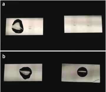
10–30 min. The dehydrated lipid forms a beveled transparent film with salt crystals in the center (Fig. 5a, right side).
Glycerol prevents complete dehydration.
4| Pipette 0.5 ml PBS buffer onto the dehydrated lipid
spot and rehydrate for 5 min to swell into giant vesicles (Fig. 5a, left side).
?trouBlesHootInG
5| Transfer the rehydrated vesicle suspension to the
SU-8–coated (see EQUIPMENT SETUP; Fig. 5b, right side)
or uncoated (Fig. 5b, left side) cover slip and mix with
0.5–1 ml PBS buffer. Figure 6 shows typical vesicle
suspensions on a glass cover slip before (Fig. 6a) and after
(Fig. 6b) transfer to a new cover slip. network generation ●tIMInG 60 min
6| Switch to differential interference contrast imaging on
the microscope.
7| Place the cover slip with the transferred vesicle
suspension on the microscope.
8| Attach a needle holder (Fig. 3c, top) and an electrode
holder (Fig. 3c, bottom) to the micromanipulator
(see Fig. 2b).
9| Take up 25–100 µl PBS buffer into an Eppendorf microloader tip using an automatic pipette.
a
b
Figure 5 | Lipid dehydration/hydration on no. 1 microscope cover slips and subsequent transfer. (a) Cover slips with two 5-µl lipid suspension droplets after desiccation (right) and rehydration (left). The lipid droplets dehydrate to form beveled spots with buffer salt crystals in the center. (b) After rehydration, the droplets are transferred to SU-8 surface-modified (right) or unmodified (left) borosilicate glass cover slips.
©
2011
Nature
America,
Inc
. All rights reserved.
10| Insert the long, narrow microloader tip into the back
end of a capillary needle (produced as described in the
EQUIPMENT SETUP) and backfill with 15 µl of the buffer; avoid bubble formation.
crItIcal step Air bubbles trapped in the tip will interfere with the microinjection and electroporation. Use only
filamented glass capillaries, as the filament guides the liquid into the tip. Bubbles formed occasionally in the needle tip can be easily displaced by repeated pumping action of the automatic pipette.
11| Insert the backfilled capillary needle into the capillary holder. Fasten the holder head so that the capillary is held
pressure-tight.
12| Attach the supply tube of a FemtoJet injection pump to the end of the capillary holder. Adjust the compensation
pressure to 2–3 hPa.
13| Attach a carbon fiber microelectrode (produced as described in the EQUIPMENT SETUP) to the electrode holder.
14| Connect the positive pole of a pulse generator to the capillary holder center contact, and the negative pole to the silver
wire of the carbon fiber microelectrode.
15| Use the coarse micromanipulators on the stage (see Fig. 2b) to bring microelectrode and needle close to the center of
the cover slip, above the objective aperture.
16| Focus the microscope on the surface and locate the vesicles.
17| Refocus the microscope ~100 µm above the surface and then manipulate both needle and microelectrode into focus, using first the coarse and then the fine micromanipulators. Slowly descend with the focus to the surface, adjusting the needle height accordingly with the fine micromanipulators.
?trouBlesHootInG
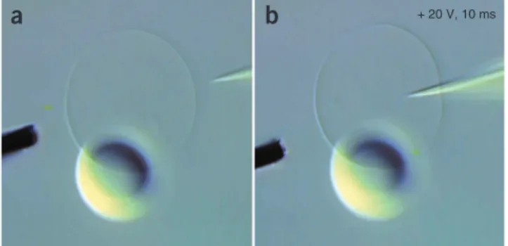
18| Select a vesicle and manipulate microelectrode and needle to opposite sides of the vesicle (Fig. 7a).
?trouBlesHootInG
19| Bring the needle in contact with the vesicle, reduce the compensation pressure to 0 hPa and apply a pulse of 20 V,
10 ms duration to the membrane. Brief motion of the membrane near the needle is noticeable. Manipulate the needle into the vesicle using the fine micromanipulators (Fig. 7b). If the needle does not penetrate the membrane, repeat the pulse and
then increase the voltage by increments of 5 V, until the membrane responds. Depending on the size of the needle orifice, the necessary electroporation voltage varies.
crItIcal step Proper pulse parameters and coordination between the needle translation, pulsing and simultaneous
reduction of compensation pressure is important to introduce the needle. Injection pulse voltages over 30 V and of durations over 100 ms should be avoided. They result in rapid decay of the carbon fiber microelectrode.
?trouBlesHootInG
a
b
+ 20 V, 10 msa
b
Figure 6 | Rehydration/swelling of lipid preparations. (a) DIC micrograph of swelling lipids after addition of buffer to a dehydrated lipid droplet. Large numbers of vesicles of different sizes at different stages of swelling and a mostly lipid-covered surface are visible. (b) After transfer of the buffer containing the swollen liposomes to a new cover slip, a greatly reduced number of GUVs is immobilized on a clean substrate surface.
Figure 7 | Initial stage of network fabrication. (a) A GUV with attached multilamellar lipid reservoir is arranged between a 5-µm carbon fiber microelectrode and an injection capillary needle. Both needle and electrode are positioned by water-hydraulic micromanipulators. (b) Application of an electroporation pulse ( + 20 V, 10 ms) with
simultaneous translation at 0 hPa backflow compensation pressure inserts the needle into the vesicle. The membrane closes around the needle and self-seals instantly.
©
2011
Nature
America,
Inc
. All rights reserved.
20| Increase the compensation pressure to 10–15 hPa, and
slowly retract the needle with ~5 µm s − 1 linear velocity
(Fig. 8a). As soon as the needle leaves the vesicle, a daughter
vesicle is formed at the tip, constantly growing in size.
crItIcal step Position the vesicle close by the mother, to ensure further growth, and increase the compensation pressure
to 30 hPa. The greater the distance, the slower the new vesicle will increase in size, even at high injection pressure.
?trouBlesHootInG
21| When a desired size is reached, reduce the compensation pressure to 1–2 hPa and manipulate the vesicle to a position
to adhere it to the surface (Fig. 8b).
22| Adjust the microscope focus close to the surface (~10 µm down) so that the needle touches the surface lightly. Pause several minutes to let the vesicle adhere tightly. Reverse polarity at the pulse generator. Slowly retract the needle and apply a pulse of 20 V, for 10 ms duration, to release the vesicle. Manipulate the needle up, and switch back to normal pulse polar-ity. A two-vesicle network has been created, which is the foundation for each of the three following transport experiments.
crItIcal step Repeat the procedure either at the mother or the new daughter vesicle to create further daughter vesicles.
If the procedure is repeated at the daughter vesicle, a linear network ensues (Fig. 8c), if at the mother vesicle, a branched
network forms (Fig. 9a,b). Figure 9c shows an example of a branched network on the first daughter vesicle, which is created
either directly from the daughter vesicle or, alternatively, by translating a vesicle along an existing nanotube16,31. Once-used
needles can be reused for further injections, as long as sufficient backfilled solution remains and the tip is not damaged or contaminated. If a high membrane tension regime for the network is desired, the multilamellar reservoir can be cleaved from the network by means of the carbon fiber microelectrode.
?trouBlesHootInG
transport experiments within networks
23| Transport experiments within networks can be undertaken using option A for diffusion-driven transport, option B for
Marangoni transport or option C for electrophoretic transport:
(a) Diffusion-driven transport in networks ●tIMInG 140 min
(i) Add 10 µl membrane staining dye solution in DMSO to the PBS buffer droplet containing the vesicle network from Step 22 using an automatic micropipette. Wait 5 min for the dye to migrate into the vesicle membranes (Fig. 10a,b).
crItIcal step This transport mode is most conveniently carried out using confocal microscopy imaging, allowing
two different excitation wavelengths for membrane dye and injected nanoparticles. The dye amount in this step is adequate for confocal microscopy. The observed fluorescence intensity depends on excitation light intensity and camera sensitivity. Check the fluorescence intensity and add another aliquot if desired. If DiD (oil) membrane staining dye was added to the initial liposome preparation (see REAGENT SETUP), there is no need to add it here.
(ii) Pull a new injection capillary and backfill it with 15 µl of filtered fluorescent nanoparticle suspension (0.02% solid content, see REAGENT SETUP).
(iii) Remove the needle slowly and carefully from the two-vesicle network on the cover slip surface using the fine micromanipulator, followed by the coarse micromanipulator.
a
b
c
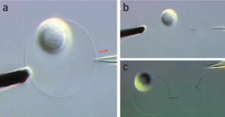
Figure 8 | Stepwise fabrication of a linear network from a single GUV/MLV. (a) After penetration of the membrane, a continuous injection pressure of 10–15 hPa is set and the needle is retracted with ~5 µm s − 1 linear velocity as
indicated by the red arrow. (b) A daughter vesicle is forming at the tip of the needle, constantly growing in size. (c) The vesicle is adhered to the surface and the process is repeated to generate further containers, if desired, with a needle of different content to generate diverse internal volumes.
a
c
b
Figure 9 | Stepwise fabrication of a branched network from a single GUV/MLV. (a–c) After generation of the first daughter vesicle (a), a second vesicle can be generated from the mother vesicle (b) and positioned adjacent to the first daughter vesicle (c). The flexible nanotube migrates along the existing tube in a zipper-like fashion38 between the two already
surface-adhered vesicles, leading to a tube between the two daughter vesicles. Additional vesicles can thus be created and connected to selected containers.
©
2011
Nature
America,
Inc
. All rights reserved.
(iv) Remove the needle from the droplet using the coarse micromanipulators. Inspect the network and ensure that both vesicles are firmly attached to the surface.
(v) Replace the injection needle with the one backfilled with fluorescent nanoparticle suspension from Step 23A(ii) and move it to the surface, close to the mother vesicle.
?trouBlesHootInG
(vi) Inject the nanoparticle suspension into the mother vesicle for 4–5 s at 30 hPa injection pressure. Figure 10c
shows a confocal microscopy image of a two-vesicle network immediately after injection of fluorescent nanoparticles (t = 0 min) into the mother vesicle.
?trouBlesHootInG
(vii) Retract the needle carefully and move it out of the droplet with the fine and then the coarse micromanipulators. (viii) Wait for 60 min, with the excitation source blocked or turned off. Occasionally, check the fluorescence from the
daughter vesicle to ensure vesicle integrity. Figure 10d shows a confocal microscopy image at t = 120 min, showing
fluorescence from the nanoparticles in the daughter vesicle.
crItIcal step Other fluorescent dyes or nanoparticles are appropriate, depending on the available excitation
wavelengths. If stained membranes are to be used on a regular basis, membrane-soluble fluorescent dye can be added to the initial vesicle preparation. Confocal microscopy is the most suitable technique for diffusion-driven transport experiments31, but wide-field laser fluorescence microscopy is also appropriate.
?trouBlesHootInG
(B) Marangoni transport in networks ●tIMInG 60 min
(i) Inspect the orientation of the newly created two-vesicle network from Step 22 to ensure that the daughter vesicle can be reached by both the carbon fiber and the needle without affecting the mother vesicle. If necessary, readjust the angle of fiber and/or needle toward the network such that only the daughter vesicle is affected by their translational motion (Fig. 11a).
crItIcal step This transport mode is most conveniently carried out using DIC microscopy imaging.
(ii) Move the carbon fiber and the needle to opposite sides of the daughter vesicle, holding it in a pincer-like manner (Fig. 11b).
crItIcal step Be careful not to cleave the multilamellar reservoir off the mother vesicle in the network, because it
is needed as lipid supply for the transport process.
(iii) Manipulate the needle toward the microelectrode with the fine manipulators (Fig. 11c, blue triangles). Adjust the
position of the pincers so that the elastic vesicle cannot move out. Observe Marangoni flow toward the daughter
Figure 10 | Confocal microscopy images showing diffusive transport of internalized 20-nm fluorescent latex nanoparticles between container vesicles through a nanotube. The membrane is stained with DiD, a lipophilic carbocyanine dye (magenta), and the internalized hydrophilic nanoparticles are modified with a fluorescent rhodamine dye (cyan). The excitation wavelength λexc = 633 nm for DiD (oil),
for the internalized nanosphere particles it is 495 nm and the emission bands were set to 640–690 nm and 505–545 nm, respectively. (a) Bright-field (transmission) image of the mother vesicle before network generation. (b) Confocal fluorescence micrograph of the two-vesicle network; the membrane fluorescence channel is selectively displayed. (c) Confocal fluorescence micrograph of the two-vesicle network immediately after nanoparticle injection (0 min). The nanoparticle fluorescence channel is selectively displayed. (d) Confocal fluorescence micrograph of the same fluorescence channel after 120 min, showing the migrated particles in the daughter container and the nanotube. The detector gain has been increased in comparison to c, to better visualize the fluorescence from the nanotube.
a
b
c
d
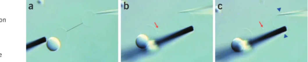
Figure 11 | Marangoni transport along a lipid nanotube in a two-vesicle network. (a) Generation of the network by electroporation and pressure injection to a MLV-connected GUV. A small vesicle is entrapped at the tube entrance close to the mother vesicle. (b) Carbon microelectrode and injection needle are positioned in a pincer-like arrangement
around the daughter vesicle. The red arrow shows the small entrapped vesicle, which starts to move along the tube. (c) Force is exerted upon the vesicle, depicted by the blue arrowheads in the panel. The force increases lateral membrane tension in the vesicle, which is released by spontaneous Marangoni flow of membrane material from the GUV-connected MLV along the tube. The small vesicle is being carried along toward the source of tension, depicted by the position of the red arrows.
©
2011
Nature
America,
Inc
. All rights reserved.
vesicle on membrane-bound objects entrapped in the tube, such as particles or small unilamellar vesicles (Fig. 11c).
(iv) Release the pincers from the daughter vesicle by means of the fine micromanipulator. Observe Marangoni flow in the opposite direction, toward the mother liposome.
(c) electrophoretic transport in networks ●tIMInG 60 min
(i) Pull an injection capillary and backfill it with 15 µl of filtered fluorescent nanoparticle suspension (0.02% solid content, see REAGENT SETUP).
(ii) Ensure that both mother and daughter vesicles of the newly created two-vesicle network from Step 22 are firmly adhered to the surface.
crItIcal step This transport mode is most conveniently carried out using laser-induced fluorescence wide-field
microscopy imaging.
(iii) Remove the needle slowly and carefully from the two-vesicle network on the cover slip surface using the fine micromanipulator, followed by the coarse one. Replace the injection needle for the one backfilled with nanoparticle solution from Step 23C(i) and move it to the surface, close to the mother vesicle.
?trouBlesHootInG
(iv) Microinject the nanoparticle suspension into the mother vesicle.
?trouBlesHootInG
(v) Remove the needle and microelectrode carefully from the droplet, using the fine and then the coarse micromanipulator. (vi) Mount two Ag/AgCl electrophoresis electrodes to the electrode holders.
(vii) Immerse the electrodes and bring them close to the target vesicle (Fig. 12a).
?trouBlesHootInG
(viii) Connect a DC power supply (minimum output: 250 mV) in parallel to the pulse generator.
(ix) Make sure that the DC power supply is turned off. Bring one of the electrodes in contact to the vesicle and apply a pulse of 20 V, for 10 ms duration, using the pulse generator. Insert the needle into the vesicle.
(x) Bring the other electrode close to the vesicle, so that it touches the membrane. Inverse pulse polarity. Apply a pulse of 20 V, for 10 ms duration, using the pulse generator. Insert the second needle into the vesicle.
(xi) Pull one electrode out of the vesicle and create a nanotube.
(xii) Turn the pulse generator off. Adjust the DC power supply to 100–250 mV. Set the positive pole to the electrode inside the vesicle, if transport of negatively charged particles from the tube into the vesicle is desired (Fig. 12b),
or to the electrode at the end of the tube, if electromigration from the vesicle through the nanotube is desired (Fig. 12c). Turn on the DC power and record electromigration. Reverse polarity for a reverse of transport
direction (Fig. 12c).
crItIcal step Single nanoparticles and polyelectrolytes, such as DNA, aggregate clusters of nanoparticles and
small vesicles on the tube, are subject to electrophoretic transport through nanotubes. Injection of such materials can require larger injection needle orifices, typically ~500 nm, to avoid clogging. Electrophoresis of nanoparticles in networks can be beneficially combined with single-particle detection in a confocal microscopy setting35.
?trouBlesHootInG
Troubleshooting advice can be found in table 1.
a
b
+ 250 mV
– 250 mV
c
Figure 12 | Electrophoretic transport of carboxylated nanoparticles alonga lipid nanotube in a two-vesicle network. (a) Bright-field DIC microscopic image of a vesicle with internalized 20 nm carboxylated fluorescent latex beads in between two gel-capped needles with internal Ag/AgCl electrodes. The spot at the tip of the right needle is a small fraction of the hydrogel plug that has been ejected from the needle during membrane electroporation. (b) A nanotube entrapped aggregate of 20-nm latex beads is transported along the tube toward the positive electrode (yellow arrow). The excitation wavelength for the fluorophore is 488 nm. (c) Reversing the polarity reversed transport direction (yellow arrow). The electrolyte-filled gel-capped needles prevent bulk liquid flow, but allow charges to pass through the network.
©
2011
Nature
America,
Inc
. All rights reserved.
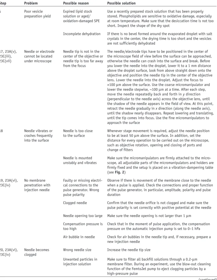
taBle 1 | Troubleshooting table.
step problem possible reason possible solution
4 Poor vesicle preparation yield
Expired lipid stock solution or aged/ oxidation-damaged SPE
Use a recently prepared stock solution that has been properly stored. Phospholipids are sensitive to oxidative damage, especially at room temperature. Make sure that the desiccation time is not too short. Inspect the shape of the dry spot
Incomplete dehydration If there is no bevel formed around the evaporated droplet with salt crystals in the center, the drying time is too short and the vesicles are not sufficiently dehydrated
17, 23A(v), 23C(iii), 23C(vii) Needle or electrode cannot be located under microscope
Needle tip is not in the center of the objective or needle tip is too far away from the focus
The needle/electrode tips have to be positioned in the center of the microscope field of view before the surface can be approached, otherwise the needle can crash into the surface and break. Before you lower the needle into the droplet, lower it to a 1 mm distance above the droplet surface, look from above straight down onto the objective and position the needle tip in the center of the objective lens. Lower the needle into the droplet. Adjust the focus to >100 µm above the surface. Use the coarse micromanipulator and lower the needle stepwise, ~100 µm at a time. After each step, move the needle repeatedly back and forth in y direction (perpendicular to the needle axis) across the objective lens, until the shadow of the needle appears in the field of view. At this point, retract the needle gradually in x direction (along the needle axis), until the shadow nearly disappears. Repeat lowering and translating, until the tip comes into focus. Use the fine micromanipulators to approach the surface
18 Needle vibrates or crashes frequently into the surface
Needle is too close
to the surface Whenever stage movement is required, adjust the needle position to be at least 50 µm above the surface. In addition, set the distance for every operation to be carried out on the microscope, such as objective rotation, opening and closing of ports and change of filters
Needle is mounted unstably and vibrates
Make sure the micromanipulators are firmly attached to the micro-scope, all adjustable parts of the micromanipulators and holders are firmly fixed and the setup is placed on a vibration-dampening table (see Fig. 2) 19, 23A(vi), 23C(iv) No membrane penetration with injection needle
Faulty or missing electri-cal connections to the pulse generator. Wrong pulse polarity
Observe if there is movement of the membrane close to the needle when a pulse is applied. Check the connections and proper function of the pulse generator, in particular, amplitude, polarity and pulse duration
Clogged needle Confirm that the needle orifice is not clogged and make sure the pulse polarity is set correctly with positive potential at the needle Needle opening too large Make sure the needle opening is not larger than 1 µm
Compensation pressure is
too high Check that in the moment of pulse application, the compensation pressure on the automatic injection pump is set to 0–1 hPa Air bubble in needle Check for air bubbles in the needle tip and, if necessary, prepare a
new injection needle 20, 23A(vi),
23C(iv) Needle becomes clogged Wrong needle size Increase the needle tip size Unwanted particles in
injection solution Make sure to filter all backfill solutions through a 0.2-µm membrane filter. During an experiment, use the blow-out cleaning function of the FemtoJet pump to eject clogging particles by a high-pressure pulse
©
2011
Nature
America,
Inc
. All rights reserved.
●tIMInG
The protocol requires the preparation of a liposome suspension, which takes ~18 h to complete. Network fabrication itself takes ~4 h in a case in which all necessary components, such as surfaces, capillaries and reagents, are to be prepared
ex novo. This time is reduced to ~90 min if these prerequisites are met beforehand. Transport experiments require between
60 and 120 min in addition to this time, depending on the transport mode. The procedures described here are basic procedures for two-vesicle networks. Depending on the complexity and intended purpose of the network created, the time requirements will be accordingly larger.
preparation steps
Liposome preparation: 18 h (once prepared, lasts for multiple experiments) Buffer preparation: 15 min
Membrane staining dye solution and nanoparticle suspension preparation: 30 min Cover slip surface treatment: 60 min (8 pieces)
Capillary needle preparation: 15 min (10 pieces)
Carbon fiber electrode fabrication: 60 min (including epoxy hardening) Electrophoretic transport pipette preparation: 60 min (three pieces)
protocol
Steps 1–5, de-/rehydration of lipid: 30 min Steps 6–22, network generation: 60 min
Step 23A, diffusion-driven transport in networks: 140 min Step 23B, Marangoni transport in networks: 60 min Step 23C, electrophoretic transport in networks: 60 min
antIcIpateD results
The protocol presented here details the preparation of simple NVNs, consisting of two interconnected vesicles in an open buffer droplet under a microscope, as depicted in Figure 8b. Initially, unilamellar vesicles associated with multilamellar
membrane reservoirs are generated from a liposome suspension (Fig. 6a) and transferred onto a clean, surface-treated cover taBle 1 | Troubleshooting table (continued).
step problem possible reason possible solution
22 Poor surface adhesion and vesicle stability. Surface adhesion is too strong, vesicles flatten on the surface. Surface adhesion is too weak, vesicles will not adhere
Old, contaminated or uncoated surface
Long experiment causes droplet evaporation and osmotic stress, which collapses vesicles
Depending on the surface used for network building, vesicle adhesion differs. Use a clean, freshly produced coated surface or, for short experiments, a cover slip directly out of the box. Never reuse surfaces, as lipid spreading occurs, which will contaminate the surface permanently
If experiments are prolonged over several hours, water evaporation from the open droplet will change the osmotic conditions and destabilize the liposomes. Pure water should be added accordingly to the sample in regular intervals. A programmable syringe pump for automatic dispensing is recommended
23A(viii) Network contents
not visible Photobleaching A common problem of fluorescent dyes is rapid photobleaching, especially in wide-field laser imaging. Fluorescein-based dyes bleach almost instantly and are not suitable for diffusion studies or prolonged imaging
Loss of contents through
leaking Some fluorescent dyes have the tendency to leak out from vesicles, in particular, when electric pulses are applied in the system, which open membrane pores. If such problems occur, fluorescent nanoparticles provide an alternative. Either quantum dots or fluorescent latex beads are available in sizes that can be injected with the current protocol (see Fig. 10)