BASE STATION COOPERATION IN MULTIPLE
INPUT MULTIPLE OUTPUT ORTHOGONAL
FREQUENCY DIVISION MULTIPLE ACCESS
SYSTEMS
a thesis
submitted to the department of electrical and
electronics engineering
and the institute of engineering and sciences
of bilkent university
in partial fulfillment of the requirements
for the degree of
master of science
By
Turgut Barı¸s Tokel
August 2009
I certify that I have read this thesis and that in my opinion it is fully adequate, in scope and in quality, as a thesis for the degree of Master of Science.
Assist. Prof. Dr. Defne Akta¸s (Supervisor)
I certify that I have read this thesis and that in my opinion it is fully adequate, in scope and in quality, as a thesis for the degree of Master of Science.
Prof. Dr. Erdal Arıkan
I certify that I have read this thesis and that in my opinion it is fully adequate, in scope and in quality, as a thesis for the degree of Master of Science.
Assoc. Prof. Dr. Ali ¨Ozg¨ur Yılmaz
Approved for the Institute of Engineering and Sciences:
Prof. Dr. Mehmet Baray
ABSTRACT
BASE STATION COOPERATION IN MULTIPLE
INPUT MULTIPLE OUTPUT ORTHOGONAL
FREQUENCY DIVISION MULTIPLE ACCESS
SYSTEMS
Turgut Barı¸s Tokel
M.S. in Electrical and Electronics Engineering
Supervisor: Assist. Prof. Dr. Defne Akta¸s
August 2009
Newly emerging advancements such as multiple input multiple output (MIMO) and orthogonal frequency division multiple access (OFDMA) techniques become indispensable parts of today’s wireless systems such as WiMAX (IEEE 802.16 standard) since they can increase the supportable data rates significantly. How-ever, achieving the maximum spectral efficiency in a MIMO system requires perfect channel state information (CSI) at the transmitter side and multicarrier nature of OFDMA systems increase the necessary CSI feedback from users to base stations remarkably. To further increase the supportable data rates, us-ing frequency reuse factor of 1 in the system is also mandatory. Unfortunately, this results in significant cochannel interference (CCI) observed especially by the users near cell edges, which can severely degrade the system spectral efficiency. To cope with this problem, base station cooperation may play an important role. In this thesis, the problem of cooperative data transmission from base stations to users in multicellular MIMO-OFDMA systems is considered. An efficient coop-erative scheduling and data transmission scheme, requiring limited CSI feedback from users to base stations and also limited information exchange between the base stations, is proposed. The numerical results demonstrate that, the proposed algorithm offers considerable spectral efficiency gains compared to conventional frequency reuse and noncooperative schemes, under severe CCI conditions.
Keywords: Base Station Cooperation, Multiple Input Multiple Output (MIMO),
Orthogonal Frequency Division Multiple Access (OFDMA), Limited Channel State Information (CSI) Feedback.
¨
OZET
C
¸ OK G˙IRD˙IL˙I C
¸ OK C
¸ IKTILI D˙IKGEN FREKANS B ¨
OLMEL˙I
C
¸ OKLU ER˙IS¸˙IM S˙ISTEMLER˙INDE TELS˙IZ ER˙IS¸˙IM
TERM˙INALLER˙IN˙IN ˙IS¸B˙IRL˙I ˘
G˙I
Turgut Barı¸s Tokel
Elektrik ve Elektronik M¨uhendisli˘gi Y¨uksek Lisans
Tez Y¨oneticisi: Yar. Do¸c. Dr. Defne Akta¸s
A˘gustos 2009
Yeni geli¸sen ¸cok girdili ¸cok ¸cıktılı (MIMO) dikgen frekans b¨olmeli ¸coklu eri¸sim (OFDMA) teknikleri desteklenebilir veri hızlarını ¨onemli ¨ol¸c¨ude arttırmaları ne-deniyle WiMAX (IEEE802.16 standardı) gibi g¨un¨um¨uz kablosuz ileti¸sim teknolo-jilerinin vazge¸cilmez bir par¸cası olmu¸slardır. Ancak, ¸cok girdili ¸cok ¸cıktılı sis-temlerden tam verim alınabilmesi i¸cin vericilerde tam bir kanal durum bilgisi gerekmektedir. Bu ise, dikgen frekans b¨olmeli ¸coklu eri¸sim sistemleri gibi ¸cok ta¸sıyıcılı sistemlerde kullanıcılardan telsiz eri¸sim terminallerine ¨onemli ¨ol¸c¨ude bir kanal bilgisi geribeslemesi gerektirmektedir. Kullanıcı veri hızlarını daha fazla arttırabilmek i¸cin bu sistemlerde frekans yeniden kullanım fakt¨or¨un¨un 1 olmasına da ihtiya¸c vardır, fakat bu ¨ozellikle h¨ucre sınırlarındaki kullanıcıların ¨onemli ¨ol¸c¨ude ortak kanal giri¸simine (CCI) maruz kalmalarına ve sistem spektral ver-imlili˘ginin d¨u¸smesine neden olur. Telsiz eri¸sim terminalleri i¸sbirli˘gi h¨ucreler arası giri¸simin azaltılmasında ¨onemli bir rol oynabilmektedir. Bu tezde ¸cok h¨ucreli ¸cok girdili ¸cok ¸cıktılı, dikgen frekans b¨olmeli ¸coklu eri¸sim sistemlerinde, telsiz eri¸sim terminallerinden kullanıcılara i¸sbirlikli veri iletimi ve ¸cizelgeleme yapılan, kul-lanıcılardan telsiz eri¸sim terminallerine sınırlı kanal bilgisi geribeslemesi ve aynı zamanda telsiz eri¸sim terminalleri arasında sınırlı veri payla¸sımı gerektiren bir al-goritma ¨onerilmi¸stir. Sayısal sonu¸clar bu alal-goritmanın, ciddi ortak kanal giri¸simi ko¸sullarında, geleneksel frekans tekrar kullanım ve i¸sbirliksiz y¨ontemlerden daha iyi bir ba¸sarım sa˘gladı˘gını g¨ostermi¸stir.
Anahtar Kelimeler: Telsiz Eri¸sim Terminallerinin ˙I¸sbirli˘gi, C¸ ok Girdili C¸ ok C¸ ıktılı Sistemler, Dikgen Frekans B¨olmeli C¸ oklu Eri¸sim, Sınırlı Kanal Durum Bilgisi Geribeslemesi
ACKNOWLEDGMENTS
I would like to thank my supervisor Assist. Prof. Dr. Defne Akta¸s for her guid-ance and support throughout my graduate education and my thesis research, and Professors Erdal Arıkan and Ali ¨Ozg¨ur Yılmaz for being members of my thesis defense committee.
I would also like to thank my family and friends for their encouragements and endless support during my graduate studies.
Finally, I would like to thank European Commission 7th Framework Programme
WiMAGIC Project, TUBITAK Career Program 107E199 Project and TUBITAK BIDEB for their financial support.
Contents
1 Introduction 1
1.1 Motivation . . . 1
1.2 Related Work . . . 2
1.3 Contributions of This Thesis . . . 5
1.4 Thesis Organization . . . 5
1.5 Notation . . . 6
2 Background 7 2.1 Multiple Input Multiple Output Systems . . . 7
2.2 Orthogonal Frequency Division Multiplexing . . . 11
2.3 Orthogonal Frequency Division Multiple Access . . . 13
2.4 Cochannel Interference and Frequency Reuse . . . 14
2.5 Multicellular System Model . . . 15
2.5.1 Signal Model . . . 15
2.5.2 Cellular Model . . . 17
3 Cooperative Transmission and Scheduling Algorithm 18 3.1 Transmission Strategies . . . 19
3.2 Transmit Beamforming . . . 20
3.3 Receive Beamforming . . . 21
3.4 Subchannelization . . . 23
3.5 Scheduling . . . 23
3.6 Power Control . . . 26
3.7 Modifications to the Algorithm . . . 29
3.7.1 Transmit Beamformer Optimization . . . 29
3.7.2 Feedback Reduction . . . 30 3.8 Fairness . . . 31 3.9 Practical Considerations . . . 33 3.9.1 Distance Measurements . . . 33 3.9.2 Synchronization . . . 33 3.9.3 Intercarrier Interference . . . 33 4 Numerical Results 36 4.1 Comparison of Transmission Schemes . . . 36
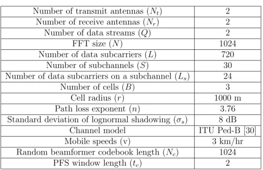
4.2 Simulation Parameters . . . 38
4.3 Simulation Results . . . 40
4.3.1 Comparison of Transmission Strategies . . . 40
4.3.2 Maximum Sum Rate Scheduling . . . 43
4.3.3 Proportionally Fair Scheduling . . . 46
4.3.4 Power Control . . . 49
4.3.5 Transmit Beamformer Optimization . . . 50
4.3.7 Intercarrier Interference Analysis . . . 54
4.4 Feedback and Backhaul Load . . . 55
List of Figures
2.1 2 x 2 MIMO channel. . . 8
2.2 Diagonalization of 2 x 2 MIMO channel. . . 9
2.3 Diagonalized 2 x 2 MIMO channel. . . 10
2.4 Division of frequency selective broadband channel into frequency flat narrowband subchannels. . . 12
2.5 Orthogonal structure of subcarriers. . . 12
2.6 Downlink and uplink frame structure of WiMAX. . . 14
2.7 Cellular model with frequency reuse factor of 3. . . 15
2.8 System model. . . 17
2.9 Cooperative cellular model with frequency reuse factor of 1. . . . 17
3.1 Illustration of data rate feedback and information exchange be-tween base stations. . . 25
4.1 cCDF of minimum received average SINR for cooperative, nonco-operative and orthogonal transmission strategies. . . 41
4.2 Comparison of percentage of the usage of cooperative and nonco-operative transmission strategies. . . 42
4.3 System sum rate for cooperative transmission scheme under MSR scheduling. . . 44
4.4 Relative gain in sum rate over noncooperative scheme under MSR scheduling. . . 45
4.5 Relative gain in sum rate over the frequency reuse scheme under MSR scheduling. . . 46
4.6 Average sum rate under PFS. . . 47
4.7 Average user data rate under PFS. . . 47
4.8 cCDFs of minimum achievable data rates of cooperative, nonco-operative and adaptive frequency reuse schemes under PFS. . . . 49
4.9 Comparison of sum rates of the cooperative scheme with different power control methods under MSR scheduling. . . 50
4.10 Comparison of sum rates of the cooperative scheme with different power control methods under PFS. . . 51
4.11 Comparison of sum rates of the proposed cooperative scheme and the modified scheme with best random beamformer selection un-der MSR scheduling. . . 51
4.12 Comparison of sum rates of the proposed cooperative scheme and the modified scheme with best random beamformer selection un-der PFS. . . 52
4.13 Comparison of sum rates of the proposed cooperative scheme and the modified scheme with reduced feedback under MSR scheduling. 53
4.14 Comparison of sum rates of the proposed cooperative scheme and the modified scheme with reduced feedback under PFS. . . 53
List of Tables
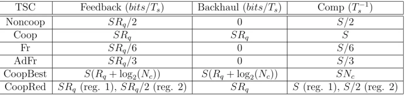
4.1 Comparison of transmission schemes in terms of feedback and backhaul loads and computational complexity. . . 38
List of Abbreviations
BS Base Station
cCDF Complementary Cumulative Distribution Function CCI Cochannel Interference
CSI Channel State Information FFT Fast Fourier Transform ICI Intercarrier Interference ISI Interstream Interference
MIMO Multiple Input Multiple Output MMSE Minimum Mean Square Error MSR Maximum Sum Rate
OFDM Orthogonal Frequency Division Multiplexing OFDMA Orthogonal Frequency Division Multiple Access PFS Proportionally Fair Scheduling
QoS Quality of Service
SINR Signal to Interference plus Noise Ratio SVD Singular Value Decomposition
Dedicated to my family who never ceases to support
me in my life . . .
Chapter 1
Introduction
Wireless communication systems, such as cellular telephone or wireless networks have become very popular in recent years. With increasing demand, the amount of research about these subjects has increased as well and new technologies are developed. However, these developments have also increased the complexity of communication systems significantly. Hence, to design a communication system which has high spectral efficiency to satisfy the data rate demands and at the same time which is practical enough to implement, has become an important and attractive area of research.
1.1
Motivation
The research presented in this thesis, is intended as a proposal for the emerging IEEE 802.16m standard [1]. Worldwide Interoperability for Microwave Access (WiMAX) is a broadband wireless metropolitan area network with large coverage area both for fixed and mobile stations. It targets high spectral efficiencies at long ranges.
In order to satisfy these requirements most of the newly emerging advance-ments must be used in a WiMAX network. Hence, multiple input multiple output (MIMO), orthogonal frequency division multiplexing (OFDM) and orthogonal frequency division multiple access (OFDMA) techniques are accepted as its es-sential parts, since they can increase the system spectral efficiency significantly. However, even in single cell multiuser scenarios, these techniques increase the
system complexity remarkably. To fully exploit the advantage of MIMO chan-nels, perfect channel state information (CSI) is needed at the transmitter, which increases the necessary feedback from users to base stations (BS) drastically, es-pecially for a multicarrier system like OFDMA. Hence, our first aim is to develop a simple and practical transmission and scheduling scheme for MIMO-OFDMA systems.
In realistic multicellular scenarios, cochannel interference (CCI), caused by the usage of same frequency band in adjacent cells, becomes an important per-formance degrading factor. In conventional cellular networks, frequency reuse scheme is used to mitigate CCI. It is a simple method where by using frequency planning, the available frequency band is divided between cells such that the distance between cells using same frequency band is increased to reduce interfer-ence power. However, this method is known to be spectrally inefficient, since the whole frequency band cannot be utilized in a given cell. Because of the high data rate targets of WiMAX, usage of frequency reuse factor of 1 is required, which indicates that the whole available frequency band is used in all cells. Hence, our second aim is to develop an algorithm to mitigate the CCI without increasing the complexity and feedback load significantly.
1.2
Related Work
In this section, firstly, studies in the literature on the problem of resource al-location in OFDMA systems with or without MIMO transmission in single or multicellular scenarios will be discussed, then the current state of art about co-operative systems will be given.
CSI at the transmitter can provide significant gains in the spectral efficiency of wireless systems. It is especially important in OFDMA systems to exploit fre-quency and multiuser diversities. Although it is assumed that users can estimate the downlink channel, this information must be fed back to BSs in the uplink phase. In the literature, there are several works on radio resource allocation and scheduling under perfect CSI assumption at the transmitter for OFDMA systems. [2] considers adaptive multiuser subcarrier, bit and power allocation, which is shown to outperform conventional multiple access schemes such as fre-quency division or time division multiple access in a single cell environment. [3] considers a subcarrier allocation scheme with adaptive modulation and coding and subcarrier reuse in multicellular systems. However, full CSI assumption at
the transmitter side, due to its multicarrier nature, becomes impractical to im-plement in OFDMA systems. Hence, some suboptimum transmission techniques requiring limited feedback are being researched [4], where the resource allocation is done with only statistical information, instead of perfect channel knowledge at BSs.
All aforementioned works consider only single antenna systems, but MIMO systems require even more CSI feedback for full efficiency. One of the attractive methods for multiantenna transmission with limited channel knowledge at the transmitter is random transmit beamforming. In the literature, this idea is first seen in [5]. For systems with multiple antennas at the transmitter side, by using pseudorandom transmit beamformer vectors, rate and dynamic range of fading can be increased to exploit multiuser diversity with opportunistic scheduling. In this way remarkable performance gains can be achieved with limited channel knowledge at the transmitter side. This article is also important for its contri-butions about proportionally fair scheduling (PFS), which is an important fair scheduling algorithm.
The random beamforming method is adapted to MIMO systems in [6] where random unitary transmit beamformer matrices, instead of vectors, are used at the transmitter to exploit spatial multiplexing gain. In [7] it is generalized to single cell MIMO-OFDMA systems. A remarkable proposal is the best random beamforming idea, where users try different random beamformers from a given codebook, find the optimum one and feed back its index together with the achiev-able data rate. In [8], layered random beamforming for MIMO-OFDMA systems is considered, where different users can be multiplexed on the spatial layers of the same MIMO channel. Finally, [9] is another interesting study which con-siders time domain random beamforming where only one transmit beamformer is used for all subchannels and can therefore reduce the feedback cost for best random beamforming. However, Vertical Bell Laboratories Layered Space Time (VBLAST) detection algorithm should be used at the receivers, which in turn increases the complexity.
The most important performance degrading factor in multicellular networks is the CCI, which can cause dramatic reductions in supportable data rates, espe-cially for the users at cell edges. In traditional cellular systems, frequency reuse scheme with a frequency reuse factor other than 1 is used to mitigate CCI. Hence, neighboring cells use different frequency bands, which results in a loss in spec-tral efficiency. In [10], different frequency reuse patterns are compared in terms
of throughput and outage probability for a WiMAX network. A noncooperative method offered to mitigate CCI is to use adaptive frequency reuse [11,12]. In this method, cell area is divided into two regions. At the inner region where the CCI level is low, subchannels are used systemwide by all BSs, while in the outer cell region where the CCI level is high, subchannels are orthogonally shared among BSs. In [13], this division is done adaptively based on signal power feedback from users to BSs for a WiMAX network.
Relays are simple structures, which are traditionally used to increase cover-age in wireless networks. They are simpler and less costly than BSs. However, the links between BSs and relays are generally wireless and less reliable. Since they can be mobile, wireless networks can extend to areas where BSs and wired infrastructure cannot be built. They can easily be used in emergency situations. In [14], it is explained how relays can be used to increase coverage area in IEEE 802.16j based mobile WiMAX systems. In the recent years, relaying also ap-peared as a possible cooperative transmission technique in the literature. In [15], two uses of relays especially in multihop sensor networks is explained. Firstly, the concept of a mobile broadband system based on fixed relay stations and secondly cooperative usage to form antenna array to exploit spatial diversity. BSs and re-lays can also make cooperative transmissions to form ”virtual” MIMO channels as explained in [16, 17].
BS cooperation is an another attractive proposal both to increase the cover-age area and to mitigate CCI. It can use existing infrastructure, since BSs are already connected to each other with high speed wired links, which have higher capacity and reliability. This eases information sharing and cooperative data transmission. A practical advantage is that handover procedure becomes easier, since users are already communicating with all BSs. Although BSs have higher processing power, they are not mobile and costly to build and operate. In [18], there is a cooperative scheme where BSs sometimes act as a relay to achieve frequency reuse factor of 1. In [19, 20], BSs act as distributive antenna systems to make collaborative MIMO transmissions. However, all these works on BS cooperation assume full CSI at BSs, which becomes even more impractical for MIMO-OFDMA systems.
1.3
Contributions of This Thesis
To the best of our knowledge, there is no study in the literature on practical resource allocation and scheduling scheme for multicellular MIMO-OFDMA sys-tems. Also, the algorithms proposing cooperation to mitigate CCI, assumes full CSI at BSs, which is not practical when combined with a multicarrier system like OFDMA. In this thesis, a cooperative transmission and scheduling scheme for multicellular MIMO-OFDMA systems is proposed. The important properties of this algorithm are as follows:
• It is of low complexity at both transmit and receive ends. • It requires limited CSI feedback from users to BSs.
• It requires limited information exchange between BSs.
• It outperforms noncooperative transmission schemes such as conventional
frequency reuse in terms of spectral efficiency.
• It maintains systemwide fairness effectively under severe CCI conditions. • It offers modifications for feedback/complexity versus spectral efficiency
tradeoffs.
1.4
Thesis Organization
The rest of the thesis is organized as follows. In Chapter 2, some background information on the properties of MIMO channels, OFDM, OFDMA and CCI is offered, which will be necessary in the development of the system model and the proposed algorithm. Furthermore, the multicellular signal and cellular models are presented.
In Chapter 3, the cooperative transmission and scheduling algorithm is ex-plained in detail, i.e., how transmitter and receiver beamformers are chosen; CCI is mitigated; a suboptimum power allocation strategy without full CSI is implemented; complexity, feedback and fairness issues are handled by increasing spectral efficiency.
In Chapter 4, the proposed algorithm is compared with the existing trans-mission methods using numerical simulations under different channel and sys-tem conditions. Also, how modifications of the algorithm affect the feed-back/complexity versus spectral efficiency tradeoffs are studied.
In Chapter 5, the thesis is concluded with a summary of results and the future research areas are discussed.
1.5
Notation
Upper case bold letters, A, are used to denote matrices. Lower case bold letters, a, are used to denote column vectors. Aij is the element of matrix A on ith
row and jth column. ai denotes the ith element of column vector a. E[.] is
the statistical expectation operator. |.| indicates the absolute value. (·)T, (·)H
and (·)−1 are the transpose, Hermitian transpose and inverse matrix operators
respectively. IN is N × N identity matrix. mod(a, b) denotes modulo of a in
base b. max
i (mini ) is the maximum (minimum) operator taken over all possible
Chapter 2
Background
2.1
Multiple Input Multiple Output Systems
MIMO systems have multiple antennas at both transmitters and receivers to ex-ploit spatial diversity and spatial multiplexing. They have become indispensable parts of today’s wireless communication systems, since they can provide signifi-cant diversity gains to reduce the error rate or multiplexing gains to increase the data rate, without increasing the necessary bandwidth of transmission.
The system considered is a multiuser MIMO system, which can be modeled as a MIMO broadcast channel, where multiple users can be served on a MIMO channel. However, WiMAX is based on orthogonal transmission, where in each cell only one user can be scheduled on a subcarrier. Hence, the results of opti-mum MIMO broadcast transmission cannot be used here. Due to orthogonality of subcarriers in OFDMA, the MIMO channels on each subcarrier can be mod-eled as a single user MIMO channel. In addition, the analysis here is information theoretic, without any assumption on the modulation, coding or capacity achiev-ing strategy. The MIMO channel is used for spatial multiplexachiev-ing, where multiple data steams are transmitted to increase the data rate.
Even single link MIMO systems have intrinsic interference due to the broad-cast nature of wireless channels, since the signals received at the receiver antennas are sum of signals transmitted from different transmit antennas. In order to fully exploit the advantage of MIMO channels, this interference should be mitigated. This process needs complex signal processing methods. The open loop method
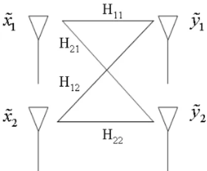
Figure 2.1: 2 x 2 MIMO channel.
uses successive interference cancelation without requiring any CSI at the trans-mitter, which shifts the burden of mitigating the interference to receiver side. Alternatively, interference mitigation can be done in a closed loop fashion re-quiring CSI at both transmitter and receiver, as it will be explained later in this section. This time the task of interference mitigation is mainly done by transmitter.
Let us now consider a simple 2 × 2 single user MIMO link with two anten-nas both at the transmitter and the receiver, where the channel is modeled as frequency flat, time-invariant channel. We would like to simultaneously trans-mit two independent data streams, where the information symbols in each data stream are linearly mapped to transmitted symbols, using beamformer matrices.
Denoting x as the information vector, where ith row corresponds to the ith stream, lets first consider an identity mapping where the 2 × 2 transmitted data vector, ˜x, is expressed as ˜x = x, i.e., each antenna transmits one data stream. The received signal is modeled as,
˜
y = H˜x + n. (2.1)
where ˜y and n are the 2×1 received data vector and the noise vector respectively. H is the 2 × 2 channel matrix. This signal model depicted in Figure 2.1, can be expressed as,
y1 = H11x1+ H12x2+ n1, (2.2) y2 = H21x1+ H22x2+ n2. (2.3)
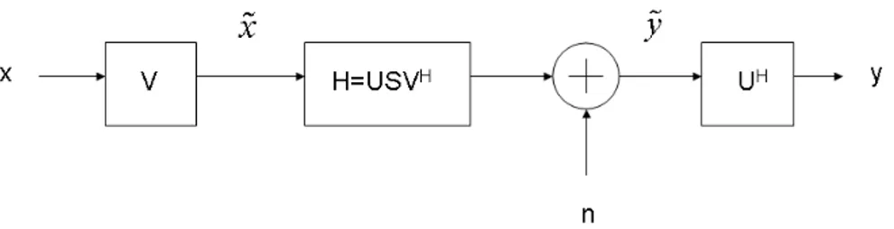
Figure 2.2: Diagonalization of 2 x 2 MIMO channel.
Definition 1. Interstream interference (ISI) is the interference between the
transmitted data streams.
If we consider a simple receiver structure, without a receive beamformer, i.e., y = ˜y, where yi is used to detect xi, the received signal to noise plus interference
ratio (SINR) for each data stream is written as,
γ1 = |H11|2E[|x1|2] |H12|2E[|x2|2] + E[|n1|]2 , (2.4) γ2 = |H22|2E[|x2|2] |H21|2E[|x1|2] + E[|n2|]2 . (2.5)
In this expression it is easy to see that the cross terms Hij for i 6= j cause the
interstream interference which reduces the performance. If the channel matrix can be diagonalized, the effectiveness of MIMO channels will increase signifi-cantly. The method used to achieve this is to employ singular value decomposi-tion (SVD) of the channel matrix by using linear processing (beamforming) at both the transmitter and the receiver, as depicted in Figure 2.2.
1. SVD of the channel matrix is found as
H = USVH, (2.6)
where U and VH are unitary matrices and S is diagonal matrix composed
of singular values of H.
2. Firstly, V is used as transmit beamformer matrix, i.e., ˜x = Vx and the received signal ˜y becomes,
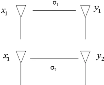
Figure 2.3: Diagonalized 2 x 2 MIMO channel.
˜
y = HVx + n. (2.7)
3. At the receiver this signal is post processed with receiver beamformer ma-trix, UH, to achieve received data vector y = UH˜y. If we use SVD of
channel matrix (2.6), y can be written as,
y = UHUSVHVx + UHn. (2.8)
4. Note that U and V unitary matrices, UHU = I, VHV = I and the
covariance of noise vector is invariant to unitary transformation. With these observations, the decision vector can be written as,
y = Sx + ˜n. (2.9)
5. If the diagonal elements of S are denoted by σ1 and σ2, the diagonalized
channel model depicted in Figure 2.3, is expressed as,
y1 = σ1x1+ ˜n1, (2.10) y2 = σ2x2+ ˜n2. (2.11)
6. As it can be seen from received SINRs in (2.12) and (2.13), the ISI is completely mitigated and yi is the sufficient statistic to decode xi. This
γ1 = |σ1|2E[|x1|2] E[|n1|]2 , (2.12) γ2 = |σ2|2E[|x2|2] E[|n2|]2 . (2.13)
If waterfilling is used to distribute the transmit power effectively to utilize the singular values of the decomposed channel, the performance can be further increased. In fact [21] showed that Figure 2.2 represents the capacity achieving scheme when channel is known at both the transmitter and the receiver.
2.2
Orthogonal Frequency Division
Multiplex-ing
One of the important problems of wireless systems is the intersymbol interference due to multipath, which occurs because of delayed versions of the same trans-mitted signal arriving at the receiver. This can cause significant performance degradation when channel delay spread is greater than symbol duration, which is the case in frequency selective broadband channels.
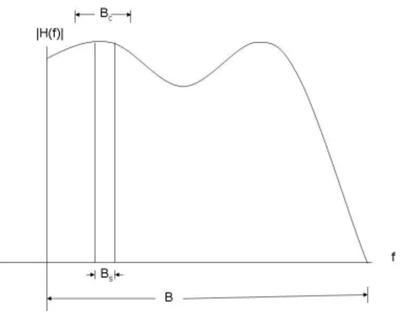
OFDM is a multicarrier modulation scheme easily implemented by fast fourier transform (FFT) algorithm to cope with this problem. In OFDM the frequency selective broadband channel of bandwidth B is divided into narrowband sub-channels of bandwidth Bs as shown in Figure 2.4. Hence, the bandwidth of each
subchannel becomes smaller than coherence bandwidth Bc and can be assumed
as an approximately flat fading channel.
In addition, by using cyclic prefixes larger than channel delay spread, in-tersymbol interference due to multipath can be completely mitigated. In cyclic prefix method, basically a fixed length of time samples from the end of input time domain signal is added to the beginning. After this operation the linear convolution between the channel and input becomes a circular convolution. Af-ter FFT operation, the frequency equalization at the receiver becomes a division operation [22], which is very practical to implement.
In OFDM, subcarrier spacing is chosen such that all subcarriers become or-thogonal as illustrated in Figure 2.5, where the frequency spectrum of OFDM
Figure 2.4: Division of frequency selective broadband channel into frequency flat narrowband subchannels.
Figure 2.5: Orthogonal structure of subcarriers.
subcarriers are plotted. Under perfect frequency synchronization, this orthogo-nal structure will be preserved. In addition, the channel should be slowly fading or approximately constant during an OFDM symbol, which is generally valid for low mobility scenarios with insignificant Doppler spread, where it can be safely assumed that intercarrier interference (ICI) is negligible. Otherwise, ICI mitigation methods should be used to maintain the orthogonal structure.
For an OFDM symbol, the number of subcarriers is equal to FFT size, N, and due to orthogonality, each subcarrier can be analyzed as an independent MIMO channel and independent data symbols are transmitted over each subcarrier.
After the inverse fast fourier transform operation, the sampled transmitted time domain signal vector sa of an OFDM symbol can be written as,
sa = √1 N N X l=1 xle2jπ(l−1)aN , (2.14)
where a is time sample index, l is the subcarrier index and xl is data symbol
transmitted on subcarrier l.
2.3
Orthogonal Frequency Division Multiple
Access
OFDMA is a multiple access scheme, which uses OFDM as the modulation scheme, where users can be scheduled in time (OFDM symbol) and/or fre-quency (subcarrier/subchannel) dimensions. When combined with opportunis-tic scheduling, which aims to maximize system spectral efficiency by giving the system resources to users with highest achievable data rate, OFDMA can pro-vide significant frequency, time and multiuser diversity gains. Unfortunately, multicarrier nature of OFDMA increases the complexity of optimum resource allocation and scheduling.
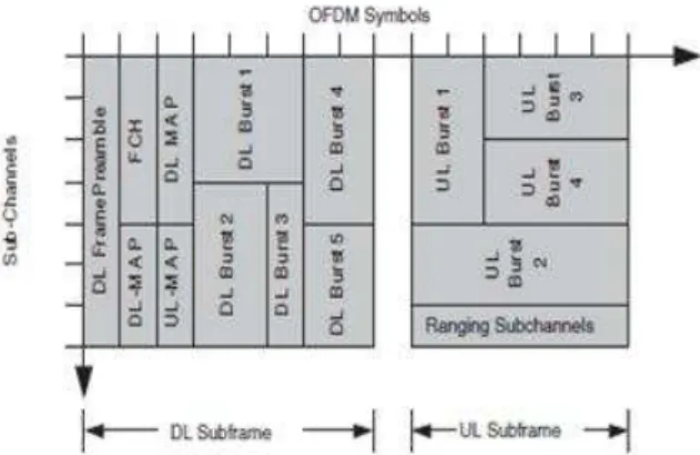
In WiMAX, subcarriers are grouped into subchannels. The smallest schedul-ing unit is called a slot which is formed in time and frequency dimensions. These slots form a frame structure as shown in Figure 2.6.1 Basically, a frame is
di-vided into downlink and uplink phases, where users can transmit or receive data. The scheduling mapping is broadcasted, feedback or other media access control (MAC) layer messages are exchanged.
The slots are assigned to users using specific scheduling algorithms, which are based on MAC layer requirements, such as quality of service (QoS), delay, service type and bandwidth requests of users [23]. However, in this thesis only resource allocation based on system or user spectral efficiency is investigated. The scheduling algorithms either aim to maximize system spectral efficiency or maintain fairness between users, or both [22]. These algorithms will be explained in detail in Chapter 3.
Figure 2.6: Downlink and uplink frame structure of WiMAX.
2.4
Cochannel
Interference
and
Frequency
Reuse
Definition 2. Cochannel interference (CCI) is the interference due to the use
of the same frequency channels for different users in the downlink phase.
For the OFDMA case, CCI occurs when different BSs schedule different users on the same subcarriers in the downlink phase. If this problem is not handled properly, it can cause a significant performance loss in multicarrier systems.
It should be noted that, because of path loss, CCI is generally assumed to be significant only in adjacent sectors.
Definition 3. Frequency reuse factor is the inverse of the ratio of frequency
channels allocated to a cell/sector/BS to the total available frequency channels in the system.
The conventional method of mitigating CCI is frequency reuse, where fre-quency reuse factor greater than 1 is used, as illustrated in Figure 2.7. In the OFDMA case, the available subcarriers are shared by BSs in an orthogonal fash-ion. Since, all available subcarriers cannot be used by all BSs at the same time, this method is known to be spectrally inefficient. In Chapter 3, a more efficient method to mitigate CCI for a system with frequency reuse factor of 1 will be presented.
Figure 2.7: Cellular model with frequency reuse factor of 3.
2.5
Multicellular System Model
2.5.1
Signal Model
The system to be considered is the downlink of a multicellular MIMO-OFDMA network. There are a total of K users, each with Nr receive antennas, and B
base stations, each with Nt transmit antennas. The OFDMA system has a total
of N subcarriers where L of them are used for data transmission. It is assumed that orthogonal OFDMA structure is preserved within a cell, i.e., only one user is scheduled on each subcarrier in a cell and it is assumed that there is no ICI between the subcarriers. For simplicity, the index for OFDM symbols is omitted.
Let kl
bbe the index of the user scheduled by BS b on subcarrier l. It is assumed
that each scheduled user has Q independent data streams to be transmitted on a subcarrier. Q is generally chosen as min(Nr, Nt) due to information theoretic
limits on spatial multiplexing. The elements of the Q × 1 data vector xl kl
b, which
is destined from BS b to user kl
b on subcarrier l, are modeled as independent and
identically distributed (i.i.d.) circularly symmetric complex Gaussian (c.s.c.g.) random variables with zero mean and unit variance.
At the BSs this data vector is firstly multiplied by a Q × Q diagonal power allocation matrix Pl
b, whose elements,
q
Pl
b,q, denote the power allocated to
sub-stream q on subcarrier l by BS b. Pl
b,q’s are subject to the power constraint, B X b=1 L X l=1 Q X q=1 Pl b,q = PT, (2.15)
where PT is the total transmission power of the system. The power-allocated
which is used on subcarrier l by BS b. Hence, the signal vector sent from BS b becomes ˜xl
b = FlbPlbxlkl b.
If we assume that the signals from the BSs arrive at user k synchronously, the signal received by user k is the sum of signals received from all BSs. After FFT operation and cyclic prefix removal, the received signal vector by user k on subcarrier l can be written as,
˜ yl k= B X b=1 Hl k,b˜xlb+ nlk, (2.16) where nl
k is the Nr× 1 noise vector whose elements are modeled as i.i.d. zero
mean c.s.c.g. random variables with variance σ2
n and Hlk,b is the Nr× Ntchannel
matrix between user k and BS b, whose elements are modeled as i.i.d. zero mean c.s.c.g. random variables with zero mean and variance 100.1X/(d
k,b)n. Here,
1. dk,b is the distance between BS b and user k; n is the path loss exponent,
used for modeling path loss. We choose this path loss model for simplicity. One can use more complicated path loss models such as the two-way model, Hata model etc. [24]
2. X is a zero mean Gaussian random variable with standard deviation σs,
used for modeling lognormal shadowing.
In order to have a simple receiver structure, it is assumed that users do not cooperate with each other and do not use complex signal processing methods to mitigate CCI and ISI, and treat these two sources of interference as additional Gaussian noise. To achieve this, user k postprocesses the received signal vector on subcarrier l by a Q × Nr receiver beamformer matrix, Glk, to form Q × 1
vector yl
k = Glk˜ykl, which is formulated in (2.17). Afterwards, each element of
the data vector xl
k can be detected individually using the corresponding element
of yl
k. The whole system model is depicted in Figure 2.8.
yl k = Glk B X b=1 Hl k,bFlbPlbxlkl b + G l knlk. (2.17)
Figure 2.8: System model.
2.5.2
Cellular Model
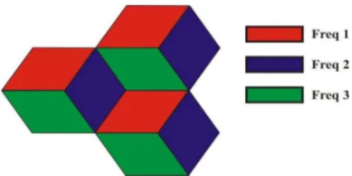
The system to be considered assumes hexagonal cellular structure with radius r and uses frequency reuse factor of 1. It is assumed that, all BSs use directional antennas and each cell is separated into three 120 degree sectors. CCI is assumed to be limited to the area generated by the intersection of these sectors of three neighboring cells, where BSs can make transmissions as a collaborative MIMO system. It is assumed that users are uniformly distributed in this area and evenly distributed in the sectors of three cells as shown in Figure 2.9.2 Each user
considers the nearest BS, as its own BS.
Figure 2.9: Cooperative cellular model with frequency reuse factor of 1.
2Note that the terms ”cell” and ”sector” are used interchangeably in the rest of the thesis,
Chapter 3
Cooperative Transmission and
Scheduling Algorithm
While designing the algorithm the first aim is to make it implementable in real world systems. Although, the methods explained in Chapter 2 increase the spec-tral efficiency of wireless communication systems, at the same time they increase the complexity of the system. The issues that should be considered for the per-formance versus complexity tradeoff problem are listed below:
1. Due to the multicarrier nature of OFDMA, full CSI assumption at BSs will be impractical since it will need a great amount of feedback from users to BSs in the uplink phase. Hence, an efficient MIMO transmission without full channel knowledge should be considered.
2. The second problem arising from the multicarrier nature of OFDMA is that the scheduling complexity and feedback load increases if users are scheduled on a subcarrier basis.
3. The usage of frequency reuse factor of 1 will cause significant CCI especially to the cell edge users. Hence, it can increase the spectral efficiency provided that the CCI is properly dealt with.
4. A proper power allocation scheme without full channel knowledge at the transmitter should be considered.
3.1
Transmission Strategies
In the proposed algorithm, first and second of the following three transmission strategies are considered. The third one is for the sake of comparison with the frequency reuse scheme and is not used in the proposed algorithm.
1. Noncooperative Transmission Strategy (TS 1): On a given subchan-nel, users are served only by the BSs in their cells. In this case three users can be served at the same time on a subchannel. Hence, there is no loss in spectral efficiency when CCI level is low.
2. Cooperative Transmission Strategy (TS 2): On a given subchannel, users are jointly served by all BSs. In this case, only one user can be served on a subchannel, without any CCI.
3. Orthogonal Transmission Strategy (TS 3): On a given subchannel, users are served only by the BSs in their cells. However, the other two BSs do not make any transmission on this subchannel. Hence, again only one user can use this subchannel with no CCI.
After defining the transmission strategies, the signal model in (2.17) can be rewritten as yl k = Glk B X b=1 b:kl b=k Hl k,bFlbPlbxlkl b + G l k B X b=1 b:kl b6=k Hl k,bFlbPlbxlkl b+ G l knlk. (3.1)
In this summation the first term corresponds to the signal received from own BSs, the second term is the received signal from interfering BSs and the last term is noise. With this signal model, the received SINR of user k on qth stream of subcarrier l for all mentioned transmission schemes can be written as,
γk,ql = | PB b=1 b:kl b=k (Al k,b)qq|2 Q P j=1 j6=q | PB b=1 b:kl b=k (Al k,b)qj|2+ Q P j=1 B P b=1 b:kl b6=k |(Al k,b)qj|2+ σn2 Q P j=1 |(Gl k)qj|2 , (3.2)
where Al
k,b = GlkHlk,bFlbPlb. In this SINR expression the numerator term is the
desired signal power. The first term of the denominator is ISI, the second is CCI which is present only when noncooperative transmission strategy is selected and the last term is noise power. Our main design objective is to optimize the system spectral efficiency expressed as,
C = K X k=1 X l∈Lk Q X q=1 log2(1 + γl k,q), (3.3)
where Lk is the set of indices of subcarriers on which user k is scheduled. In
order to optimize system spectral efficiency, the transmit beamformer matrix, Fl
b, power allocation matrix, Plb, and receive beamformer matrix, Glk, must be
jointly chosen such that the received SINRs, γl
k,q’s, are maximized. Since we
require limited information feedback from the users, the transmit beamformer and power allocation matrices should be chosen with limited channel knowledge.
3.2
Transmit Beamforming
Random transmit beamforming seems to be an attractive method for MIMO transmission with limited channel knowledge. By exploiting multiuser diver-sity and opportunistic scheduling, near optimum performances close to eigen-beamforming configuration can be achieved, especially under cooperative trans-mission, where there is no CCI.
Firstly, a random beamformer codebook Wb with length Nc is generated at
BS b, where each element is a Nt× Q unitary matrix and the wth element is
denoted as Wb(w). For each OFDM symbol the same codebook is used and for
successive subcarriers, the elements of the beamformer codebook are also selected in successive manner. Then, the beamformer matrices in (2.17) becomes,
Fl
b = ˜Vbl, (3.4)
where ˜Vl
b = Wb(mod(l, Nc)).
With this transmit beamforming method, the MIMO channel on subcar-rier l is in general not diagonalized and ISI can not be completely mitigated.
The effective channel matrix seen by user k on subcarrier l is defined as ¯
Hl
k = [Hlk,1Hlk,2. . . Hlk,B] and similarly the effective beamformer matrix as
¯ Vl
k = [( ˜V1l)T( ˜Vl2)T . . . ( ˜VlB)T]T, ∀ b : kbl = k.
Recalling Section 2.1, if the first Q rows of right singular matrix of ¯Hl k is
denoted as ˆVl
k, ISI is mitigated if and only if ( ˆVlk)HV¯kl = I. As this result gets
closer to I, the performance gets closer to eigen-beamforming configuration and with increasing number of users the probability that any one user may be in eigen-beamforming configuration will increase.
At each OFDM symbol the order of elements of the codebook is randomly changed. Hence, a different random beamformer is used on the same subcarrier on different OFDM symbols, and regardless of the velocity, each user effectively experiences a fast fading channel with increased time diversity. In addition, usage of different random beamformers on each subcarrier increases the frequency diversity, even if there is a correlation between subcarriers or subchannels.
The properties of these ˜Vl
b matrices are as follows:
1. They are unitary matrices.
2. They are selected independent of the scheduled users.
3. They are formed pseudorandomly with predefined seeds assumed to be known by all users.
4. They are chosen without any channel information.
3.3
Receive Beamforming
Assuming that users can perfectly estimate the instantaneous channel gains from all BSs and they can predetermine the transmit beamformer and power allocation matrices used by BSs on a given subcarrier, in order to maximize its received SINR user k can calculate the well-known minimum mean square error (MMSE) receiver beamformer for subcarrier l as,
Gl k = B X b=1 b:kl b=k (Dl k,b)H σ2nIQ+ B X b=1 b:kl b=k Dl k,b( B X b=1 b:kl b=k Dl k,b)H+ B X b=1 b:kl b6=k Dl k,b(Dlk,b)H −1 , (3.5) where Dl
k,b = Hlk,bFlbPlb. It should be noted that, in this formulation the first
term in the inverse operator is the noise covariance matrix, the second term is the desired signal covariance matrix and the last term is the CCI covariance matrix, absent in the cooperative transmission strategy, TS 2.
When the receiver beamformer matrix is the MMSE beamformer, the received SINR given in (3.2) can be written in a simplified form as shown in [25, 26] as,
γk,ql = 1 (Ml
k)qq
− 1, (3.6)
where Ml
k is the mean square error matrix calculated as,
Ml k = I − ( B X b=1 Dl k,b)H(Glk)H. (3.7)
The transmit beamformer matrices are already known by the users, since they are generated pseudorandomly using predetermined seeds known by the users, and are selected independent of the scheduled users and the channel conditions.
Optimum power allocation requires significant feedback and information pass-ing as discussed in Section 3.6. Therefore, we will be interested in power alloca-tion strategies that can be predetermined by users based on limited informaalloca-tion to keep the feedback and backhaul loads low.
Furthermore, in the case of noncooperative transmission, for the power allo-cation to be predetermined by the users this alloallo-cation should be independent of the users scheduled on the same subcarrier and served by other BSs. This way under the noncooperative transmission strategy, interference seen by one user in a cell will be independent of the scheduled users in other cells.
3.4
Subchannelization
In order to reduce scheduling complexity and feedback load, the available sub-carriers are grouped into subchannels. This process is done according to partial usage of subchannels (PUSC) permutation as explained in [1]. Basically, L sub-carriers are used for data transmission from a total of N subsub-carriers, after sepa-rating the rest as guard band or plot subcarriers. After a series of pseudorandom permutations, these L data subcarriers are grouped into S subchannels. These subchannels can be divided into 3 different segments, which can be assigned to 3 sectors for the conventional frequency reuse scheme. Some important properties of PUSC in WiMAX are,
1. Subcarriers of a given subchannel are distributed over the whole frequency band, which increases frequency diversity in a subchannel. However, since the permutations may distribute correlated subcarriers among subchannels, there may be a correlation between subchannels.
2. Users are scheduled on a subchannel basis but over two consecutive OFDM symbols, which decreases the scheduling complexity and feedback load since the data rate feedback must be done once two OFDM symbol. However, this may cause performance loss for high mobility scenarios, where two consecutive time slots become highly uncorrelated.
3.5
Scheduling
The scheduling algorithm is formulated in order to maximize the system spectral efficiency. Hence, the optimization problem here is to maximize the instantaneous total sum rate of all the users under the total power constraint PT. Orthogonal
structure of OFDM is preserved in each cell. Hence, total sum rate C(t) is equal to the sum of achieved rates on each subchannel Cs(t), where t is time slot or
OFDM symbol index.
C(t) =
S
X
s=1
Here, the optimization problem is equivalent to maximizing Cs(t) for each
subchannel s. Since each BS serves only one user on each subchannel, the max-imization can be done using opportunistic scheduling of the users over the sub-channels.
However, calculation of Cs(t) depends on the transmission strategy to be used
on subchannel s. Under noncooperative transmission strategy TS 1, maximiza-tion of Cs(t) is achieved when each BS schedule the user in its own cell with the
highest achievable data rate on subchannel s. Under cooperative transmission strategy TS 2, subchannel s should be allocated to the user over all the users in the system with the highest achievable rate under TS 2 on subchannel s.
In proposed algorithm, firstly each user must calculate the received SINRs given in (3.6) γl
k,q(t, i), where t indicates the time slot index and i represents the
transmission strategy, TS i, i ∈ {1, 2}. Then, the achievable data rate of user k on subchannel s for time slot t and TS i is simply,
Rs k(t, i) = X l∈Ls Q X q=1 log2(1 + γl k,q(t, i)), (3.9)
where Ls is the set of indices of subcarriers within subchannel s, with size L s.
Here, the achievable data rate on a subchannel is sum of data rates of the sub-carriers of that subchannel, because of the orthogonal structure of OFDM.
Then, each user feeds back the two data rates Rs
k(t, i) under the two
trans-mission strategies to the BS in its cell for each subchannel s. Each BS b firstly calculates the maximum of the achievable data rates under the two transmission strategies for all subchannels s over all users in its own cell as,
¯
Rsb(t, i) = max
k∈K(b)R s
k(t, i), (3.10)
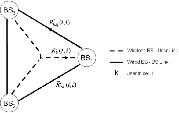
where K(b) is the set of indices of users in the cell served by BS b. BSs exchange this information over the backhaul with each other. In this case total of 2S data rates are sent by each BS over the backhaul. This procedure is depicted in Figure 3.1. The aim is to use the wired links at the backhaul of BSs instead of transmitting rate information to BSs over the wireless link, to reduce feedback load and increase reliability.
Figure 3.1: Illustration of data rate feedback and information exchange between base stations. Cs(t) = max i C s(t, i), (3.11) where Cs(t, 1) = B X b=1 ¯ Rs b(t, 1), (3.12) Cs(t, 2) = max b ¯ Rs b(t, 2). (3.13)
Recall that, the rate in (3.12) corresponds to best total rate on subchannel s at time slot t under noncooperative transmission strategy TS 1, where each BS transmits to a different user. The rate in (3.13) is the best total rate on subchan-nel s at time slot t under cooperative transmission TS 2, where all BSs transmit to the same user. Hence, the algorithm chooses noncooperative transmission, if there is no gain in terms of the sum rate from cooperation for subchannel s. This way, the scheduled user(s) and the transmission strategy to be used on each subchannel is jointly determined by all BSs using (3.11).
Let ¯ks
b(t, i) denote the index of the user maximizing (3.10) under TS i, ¯bs(t)
denote the index of the BS maximizing (3.13) and ¯is(t) denote the index of
transmission strategy TS i maximizing (3.11).
As a result, on subchannel s, if
1. ¯is(t) = 1, noncooperative transmission is done simultaneously to users
{¯ks
1(t, 1), ¯ks2(t, 1), . . . , ¯kBs(t, 1)}.
2. ¯is(t) = 2, all BSs cooperatively transmit to the user with index ¯ks
¯bs(t)(t, 2).
In this case, BS ¯bs(t) has to share the data vectors, xl
¯
ks
¯bs(t)(t, 2), for l ∈ L
s
with all BSs over the backbone.
Finally, scheduling and the corresponding transmission strategy information can then be broadcasted to all users in the system by their corresponding BS.
3.6
Power Control
So far in our discussion of the proposed algorithm, we assumed a power allo-cation scheme that can be predetermined by the users in order to compute the corresponding receiver beamformer matrices and their resulting SINR feedback before the scheduling task is performed by the BSs.
The simplest power allocation scheme under the above requirement that one can come up with is the uniform power allocation scheme where the total power is equally distributed to all subcarriers, base stations and data streams. In this case, power allocation matrices are expressed as,
Pl b =
PT
BLQIQ ∀ b, l (3.14)
However, as we will demonstrate in Section 4.3.4, the performance of the proposed algorithm can be significantly improved if power allocation is done more intelligently without increasing the feedback load that much.
The optimum power allocation maximizing the system spectral efficiency is identified by solving the following optimization problem,
max {Pl b,klb} K X k=1 X l∈Lk Q X q=1 log2¡1 + γl k,q ¢ subject to B X b=1 L X l=1 Q X q=1 (Pl b)qq = PT. (3.15)
Note that this optimization problem involves power allocation, scheduling (subcarrier allocation, i.e., determination of kl
b’s) and choosing receiver
beam-forming matrices. Since γl
k,q depends on the transmission strategy, the channel
matrix of k to all BSs, the receiver beamformer matrix of user k and the power allocation of all BSs on subcarrier l, it is a complex optimization problem that cannot be solved distributively with limited channel knowledge at BS. Therefore, we will resort to suboptimal power allocation techniques.
As mentioned earlier, since the limited channel information fed back by the users are the achievable data rates under transmission strategies TS 1 and TS 2 for each subchannel, which in turn depends on the power allocation scheme used, it would be feasible to consider a power allocation strategy that can be predetermined by the users in advance with limited information. Therefore, one can consider uniform power allocation among subcarriers and data streams to keep the complexity and feedback load of the users low. In this case,
Pl
b = PbIQ ∀ l, (3.16)
where PB
b=1
Pb = PT/(QL).
Hence, the complex optimization problem in (3.15) reduces to
max {Pb,klb} K X k=1 X l∈Lk Q X q=1 log2¡1 + γl k,q ¢ subject to B X b=1 Pb = PT/(QL). (3.17)
In the case of non cooperative transmission strategy, for the users to be able to predetermine the power allocation between base stations, the allocation
needs to be BS specific and independent of the scheduled users in other cells. Therefore, it is reasonable to assume uniform power allocation, Pb = BLQPT ∀ b,
for the noncooperative transmission strategy. This way fairness among the cells is maintained, since each BS only transmits to users in its own cell.
In the case of cooperative transmission strategy, the SINR expression is sim-plified as there is no CCI term. Therefore, users can compute the optimum power allocation between BSs. However, the SINR depends on channel matrices from all BSs to the user considered which contain both large scale fading (path loss and lognormal shadowing) and small scale fading. As a result, optimum power allocation might be different for different subcarriers. While these channels are assumed to be perfectly known at the users, BSs have limited CSI, i.e., only the knowledge of the achievable data rates on subchannels which are fed back by the users is present. Therefore, they can not perform the optimum power allocation between themselves without additional feedback from the users, i.e., 3L real numbers should be fed back.
However, one can assume that BSs can determine the distance between them and a user. As a result, they can predict the path loss. Ignoring lognormal shadowing and small scale fading, a suboptimal power allocation method based on path loss can be utilized. The proposed suboptimal power allocation for user
k under the cooperative transmission strategy is,
max {Pb} B X b=1 log2 µ 1 + Pb (dk,b)n ¶ subject to B X b=1 Pb = PT/(QL). (3.18)
Note that this power allocation is user specific, since it depends on the loca-tion of the user with respect to all BS and can be solved with the well-known waterfilling method [27]. In this way, for each subchannel and user to be sched-uled under TS 2, BSs share the total power in the subchannel in a such a way that closer BSs transmit with higher power.
It should be noted that the proposed power allocation in (3.18) is not optimal in any way, i.e., it is not maximizing the achievable data rate under TS 2. How-ever, it is simple to implement without requiring any additional feedback from the users, since it only depends on user locations and does not require any other
CSI on each subcarrier. Numerical results presented in Section 4.3.4 demonstrate that although not optimal in any way, the proposed power allocation scheme re-sults in performance gains with negligible increase in complexity and feedback load.
This power allocation scheme also demonstrates the relationship between co-operative and orthogonal transmission strategies. If we consider a scenario where a user is too far way from the BSs in other cells, all the available power will be allocated to the BS in user’s own cell, which will correspond to the orthogonal transmission strategy. However, for the scenarios where the user is closer to the cell edge, the proposed power allocation scheme will allocate the power between BSs to provide spatial diversity again, as it will be demonstrated in Chapter 4.
Finally, the power allocation scheme considered here is based on a total power constraint which is not practical. Per BS or per transmit antenna constraints are more practical as each transmit antenna typically has its own RF chain and is limited by the linearity region of its power amplifiers. However, per BS or antenna constraints are known to require complex optimization tools and increased feedback load [28]. In the proposed scheme, for users served under TS 2, there is expected to be a power imbalance between the BSs, only for the subchannels used in cooperative mode. In the long run, the transmit power of all BSs is expected to be balanced on average.
3.7
Modifications to the Algorithm
3.7.1
Transmit Beamformer Optimization
In addition to the advantages of random transmit beamforming explained in Section 3.2, it can also be used with best random beamformer selection method. The basic idea is that users calculate their achievable rates for all possible random beamformer matrices in the codebook and feed back the data rate along with the index of the random beamformer.
This method can only be used with cooperative transmission strategy. If it is used for noncooperative transmission, then transmit beamformers will not be independent of scheduled user and users can not compute their SINRs without additional knowledge about what is going on in other cells.
A codebook of length Nc needs log2(Nc) bits for indexing. If the best
beam-former is found for each subcarrier and each BS, then the feedback load increases by LB log2(Nc) bits. To reduce the feedback load it is more suitable to find a
random beamformer for each subchannel and use the following method:
To find the optimum effective beamformer matrix, users firstly calculate (3.9), recalling the codebooks are denoted as Wb(w), ∀ w ∈ [1, Nc], to find Rks(t, 2, w).
Then they find,
Rsk(t, 2) = max
w R s
k(t, 2, w). (3.19)
Afterwards, users feed back this data rate along with the corresponding ¯Ns k,
which is the single index of the random beamformer matrices in all Wb’s that
maximizes (3.19). If cooperative transmission strategy, TS 2, is chosen for sub-channel s after scheduling, then the transmit beamformers at each BS should be chosen as,
Flb = Wb( ¯N¯kss
¯
bs(t)(t,2)) ∀ l ∈ L
s. (3.20)
Note that the joint optimization of the transmit beamforming matrices for all BSs is not employed to keep the feedback load and computational complexity low. Although this method will increase the performance, along with the increased feedback, users must also calculate Nc times more data rates per subchannel.
Hence, there is a performance versus complexity and feedback load tradeoff to be considered.
3.7.2
Feedback Reduction
Although the algorithm needs limited feedback, there seems to be a possibility that the feedback load can be further reduced at the expense of some performance loss, due to the following observations:
1. If all BSs can find a user with good instantaneous channel, i.e., typically close to itself, noncooperative transmission is preferred.
2. For the cell edge users far away from their own BSs, cooperative trans-mission is preferred, since noncooperative achievable rates are very low for these users due to observed CCI levels.
These two observations and aforementioned studies about adaptive frequency reuse can bring motivation to partition the cell into two regions. A low CCI region closer to BSs (region 1) and a high CCI region near cell edges (region 2).
It is obvious that, it is not optimum to make this partitioning based only on distances due to shadowing effect. However, in a suboptimal fashion this parti-tioning can be done based on the power control method explained in Section 3.6. It is observed that, under cooperative transmission strategy TS 2, for the users close to their own BSs the power control method allocates nearly all power to their own BSs and very small power to other BSs. Typically, their cooperative rate is lower than the sum rate archived under noncooperative transmission over all cells. These users are assumed to be in low CCI region. The users, for whom the power allocation involves two or three BSs, are assumed to be in high CCI region.
Considering the first observation, firstly it seems reasonable to make region 1 users just calculate and feed back data rates for noncooperative transmission. However, due to cooperative nature of the system this can cause the following problem. If there is no user in region 1 of other cells, the noncooperative sum rate will decrease significantly. Hence, a region 1 user may never be scheduled because of this pairing problem. So, it seems more suitable for region 1 users to consider both noncooperative and cooperative transmission.
Because of the second observation, it is reasonable that region 2 users can just calculate and feed back the data rates for cooperative transmission. Hence, with this feedback reduction scheme the feedback load and computational cost can be halved for cell edge users.
3.8
Fairness
Until now, the scheduling scheme we discussed aims to maximize the total achiev-able sum rate of the users. It is known that maximum sum rate (MSR) schedul-ing results in an unfair rate allocation, because this algorithm always chooses the best user with the highest achievable data rate. Hence, a user with a very
good instantaneous channel, i.e., typically a user very close to its own BS, may dominate the channel, while a cell edge user may never be served at all.
If fairness between users is desired, i.e., all users are to achieve more or less equal average data rates at the long run, proportionally fair scheduling (PFS) can be implemented, by modifying the algorithm such that the data rate to be fed back by the users for a subchannel, ˜Rs
k(t, i), is the instantaneous achievable
data rate on that subchannel weighted with the inverse of the time averaged data rate achieved so far.
˜ Rs k(t, i) = Rs k(t, i) Tk(t) , (3.21)
where time averaged data rate Tk(t) of user k is calculated with the exponentially
weighted low pass filter
Tk(t + 1) = (1 − 1 tc )Tk(t) + 1 tc X s∈Sk Rks(t,¯is(t)). (3.22)
where tc is the window length, Sk is the set of subchannels where user k is
scheduled and Rs
k(t,¯is(t)) is the total achieved rate of user k on subchannel s
at slot t with the chosen transmission strategy. Since users’ instantaneous data rates are not normalized with the time averaged data rates averaged over the given subchannel, scheduling will be fair even in short term [8].
It is obvious that PFS is more suitable to use in practical systems; since users generally have minimum data rate requirements. One of the aims of this algorithm is to provide acceptable data rates to users who suffer from CCI the most, i.e., cell edge users. Only under PFS, every user will have a chance to be scheduled, hence gains from cooperation is expected to be more under this scheduler. Furthermore, while providing cell edge users with acceptable data rates to ensure fairness, the algorithm also targets to use system resources such as transmit power and time slots efficiently, in order not to decrease system spectral efficiency significantly.
3.9
Practical Considerations
In this section, practical issues about the underlying assumptions made in the development of the algorithm are discussed.
3.9.1
Distance Measurements
Accurate measurement of distances between BSs and users is important for the algorithm, since we assume that distance information is present both at BSs and users for the proposed power allocation strategy to work properly. This may be accomplished by using GPS devices both at BSs and mobile stations, with periodic coordinate information exchange. However, as mobility increases this measurement and information exchange should be done more often.
3.9.2
Synchronization
Synchronization is an important problem for a cooperative system, since dis-tances from BSs to a user may vary greatly. However, if BSs are synchronized based on a common timing source and downlink frames sent by BSs arrive at the users within the cyclic prefix interval [22], then there should be no synchroniza-tion problem.
For a hexagonal cellular system with radius, r = 1000 m, the largest distance, i.e., distance between 2 BSs is approximately 1732 m. Hence, the largest delay happens to be approximately 5.8 µs which is smaller than cyclic prefix time 11.43 µs [30]. Hence, there should not be a timing synchronization problem.
3.9.3
Intercarrier Interference
Intercarrier interference (ICI) is an important performance degrading factor in multicarrier systems. Even with perfect frequency synchronization, under high mobility scenarios it can cause significant performance loss. Since, the numerical results presented in Chapter 4 are for low mobility scenarios, it may be expected that the performance loss is insignificant. To study the effect of ICI on the performance of the proposed algorithm, we provide the following analysis.