Microcomputers in Civil Engineering 8 (1993) 129-139
Advanced
CAD
Environments
:
A
Knowledge-Based
Foundation
Varol Akman
Department of Computer Engineering and Information Science, Faculty of Engineering, Bilkent University, Bilkent 06533,
Ankara, Turkey
Abstract: Current computer-aided design (CAD) systems are extremely powerful tools f o r the development of products in an industrial setting. However, they still leave a lot to be desired when it comes to fu"fi1ling a designer's demands and dreams. W e believe that knowledge engineering, or more broadly artificial intelligence ( A I ) , is a promising candidate f o r providing advanced design environments. This paper proposes
assorted techniques from AI-such as logical knowledge
representation, naive physics, and commonsense
reasoning-as effective means of obtaining such
environments.
In order to make adept, temporal comments, an architecture machine must have a certain basic understanding of qualities. Though at first primitive, this qualitative appreciation itself would evolve within a value system that is very personal, between a man and a machine.?'
1 INTRODUCTION
In 1963, John McCarthy made an interesting remark. He predicted that 'the relationship between computation and mathematical logic will be as fruitful in the next century as that between physics and analysis in the last '.
What makes this observation a truly visionary one is that today McCarthy's expectation is largely fulfilled and the next century is still eight years ahead. Logic pro- gramming is now a household name and there is hardly an area of computing where logical formalisms and theories are not dominant.
Encouraged by this remarkable development, the main motivation for our work has been to investigate the use of mathematical logic in design. (The reader is
referred to various publications, listed in the References, for a review of our work; especially cf. Ref. 7.) It should immediately be confessed that doing so is swimming in dangerous waters because design is ordinarily associated with mysterious, at best intricate, mechanisms which
involve a variety of high-level cognitive p r o c e s s e ~ . ~ ~ ~ ~ ~ In other words, it is commonly thought to be difficult, if not
impossible, to pin down precisely the formal aspects of design3' Yet our approach to deal with this puzzling nature of design is decidedly formal. We think that only through a theoretical framework can we arrive at a scientific theory of design.
If logic is one important facet of our work, the other is naive physics. We believe that the emerging theories of naive physics can be used to obtain good representations of design artifacts and to reason about device behavior. Since the final outcome of a successful design is usually a physical product (at least in mechanical design), it should come as no surprise that a 'theory of design artifacts ' would be necessary for computer-aided design
(CAD) systems. So far, this theory has been largely missing. In fact, it has long been argued that a general theory of devices is essential. To quote Minsky:"
The classical idea of a simple machine-lever, wheel, inclined plane, etc.-does not capture the spirit of what is involved in today's machines because it doesn't help understand anything except the transmission of force. We cannot explain in those terms even some parts ofclockwork, such as the ratchet (an information- storage device) or the spring (an energy-storage device).
It is our belief that naive physics is a fine candidate to provide this general theory.
Caveat. It is noted that, following Ref. 17, 'we usually
do not distinguish among the areas of naive physics,
129
130 VaroI Akman
common sense theory, qualitative simulation, qualitative reasoning, and qualitative physics’.
1.1 The need for theory
CAD systems capable of giving intelligent support to designers will be important in the future.28 AS tech- nologies advance, only those systems that incorporate advanced reasoning capabilities will be able to deal with the complexity arising from the management of large quantities of design data. Intelligent CAD systems are envisaged as sophisticated design environments which support a designer’s intellectual activities with integrated design knowledge. This certainly requires that some, not necessarily perfect, concept of design is already available and this is precisely the aim of this paper, viz. to present a theory of design as particularly amenable to auto- mation. Understanding the nature of design processes and obtaining good representations of design artifacts in an evolutionary design framework are, in our view, the most urgent goals of research in intelligent CAD. The progress toward success will be measured by how much these efforts will be different from pragmatic (yet obviously significant) issues such as geometric reasoning, geometric features, solid modeling, finite elements, optimization, etc., which are aimed at realizations of CAD systems.
Caveat. Since design activities and philosophy for CAD systems are dependent on the target area, these problems can be meaningfully discussed only vis-u-vis a particular field. We take machine design as the target area.
1.2 The nature of design
Let us start with the following definitions which are taken from The New Merriam-Webster Pocket Dic- tionary, 49th printing (1972):
de’sign
\ di-kin\ vb 1: to conceive and plan out in the
mind; also: DEVOTE, CONSIGN 2: INTEND 3 : to devise for a specific function or end 4 : to make a pattern of sketch of 5 : to conceive and draw the plans for (- an airplane)-de’sign’er ndesign n 1 : a mental project or scheme: PLAN 2: a particular purpose: deliberate planning 3: a secret project or scheme: PLOT 4 pi: aggressive or evil intent-used with on or against 5 : a preliminary sketch or plan: DELINEATION 6: an underlying scheme that governs functioning, developing, or
unfolding: MOTIF 7: the arrangement of elements that make up a structure or a work of art 8 : a decorative pattern
In the light of so many meanings attached to the word design (even by a pocket-size dictionary), it is probably redundant to say that the present paper will not cover all aspects of design. Rather, it will explain a certain, hopefully original, outlook which sees design as an intellectual activity and thus tries to embody artificial intelligence (AI) techniques to automate it. Before we get into that, we want to cite a couple of observations regarding the nature of design. The following is due to Schon :29
Designers are usually unable to say what they know, to put their special skills and understanding into words. On the rare occasions when they try to do so, their descriptions tend to be partial and mistaken : myths rather than accurate accounts of practice. Yet their actual designing seems to reveal a great deal of intelligence. How, then, if we reserve ‘knowledge’ for what can be made explicit, are we to explain what designers ‘know’? And if, on the contrary, we recognize designers’ racit knowledge, what shall we say about the ways in which they hold it, or ger access to
it when they need it?
On the other hand, designing a machine, according to Newel1 and Simon, can be thought of as a search in a (usually very large) parameter space?
Designing a machine. Take as
U
the set of all possible parameter values for a machine design; take as G the subset of parameter values that: ( I ) satisfy the design specifications, and (2) meet certain criteria of cost minimization. For cases of practical interest, the set U will be immense and hence will have to be explored in somewhat systematic fashion. In early stages of the search, for example, particular design variables may be bounded, or even fixed, prior to establishing limits on the other variables. If the priorities are fairly definite, then the search tree will have hierarchic properties- the branchings at different stages referring to different classes of design variables.This paradigm of ‘ design-as-search’ is illustrated in Fig. 1.
1.3 Heterogeneous inference
Especially in the early stages of a design process heterogeneous inference-inference that proceeds from information represented in more than one form-is crucial. This idea is in the precise spirit of Barwise and Perry’s situation semantics which sees valid inference not as a relation between sentences that preserves truth but as a situated activity whose aim is the extraction of information from a situation, information relevant to the
Advanced CAD environments 131
0
f l l l p o s s i b l e p a r a m e t e r v a l u e s D e s i r a b l e p a r a m e t e r v a l u e sFig. 1. Machine design according to Newell and Simon.26
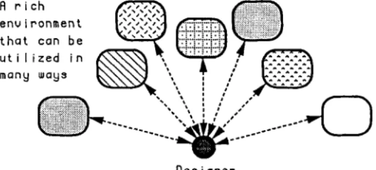
R r i c h e n v i r o n m e n t t h a t can b e u t i l i z e d i n many ways
0
D e a i g n e rFig. 2. Design process as heterogeneous inference.
R t t r i b u t e s S t r u c t u r e
Fig. 3. Design as a transformation.
person who extracts Thus, a key insight of our paper is that design is a situated activity-an activity that is carried out by an intelligent agent (designer) in a rich environment that can be utilized in many Figure
2 depicts this idea. Here, each box is a potential
knowledge source that can be utilized by the designer. Design programs assist a designer in specifying an
artifact, e.g. a house, a machine, or a n electronic circuit.
The assistance can range from mere registration of the design results to analyzing the proper functioning of the designed object, maybe through simulation. More ad- vanced forms of assistance include problem-solving activities such as optimization, routing, and even
10
suggesting a solution based on the given specifications. The latter activities become more dominant when the assistance could be extended to the earlier and more difficult phases of design.
The design process can be defined as transforming a set of specifications into a set of attributed objects which together perform as required by the specifications (cf. Fig. 3). The process can be structured in terms of stages
(e.g. analysis, synthesis, evaluation, and so on) by decomposition into subprocesses for parts of the par- titioned design. Moreover, there may be assorted forms of backtracking, iteration, detailing, etc.
In some sense, the design process can be characterized by the way it will interact with the design object. An important goal is to find the appropriate means for describing the design process and to define the semantics in terms of the design transactions. Following this, a coherent solution for integrating the various design activities as well as user interface issues.can be researched. Much of a designer's activities consist of manipula- tions of the design object to add new information and changing and inspecting. In advanced systems, the context in which these take place may vary in time. Even the purpose of such activities may initially be left unspecified. This could, in some cases, influence the way in which the corresponding transactions are visualized. A
design artifact must be properly represented to identify the status of the artifact information-proposed, fixed, changeable, etc. Much of the interaction between process representations and artifact representations is dependent on the status information. In particular, the status must be allowed to be incomplete, inaccurate, or even inconsistent (in a given intermediate situation).
2 THE PRACTICE OF CAD
We shall, as we have noted earlier, concern ourselves with mechanical CAD. We take mechanical part design (machine design) as our domain of discussion for it probably has the strongest industrial appeal. As a well- established integral part of computer-integrated manu- facturing (CIM), mechanical CAD is the backbone of today's highly industrialized world. It helps engineers to develop products ranging from the simple and ordinary (e.g. chairs, bicycles) to the complex and sophisticated (e.g. cars, aircraft). It multiplies the productivity many times and renders, using CIM technique^,^^ robust products.
However, the practice of CAD in the industry is not
without problems. It is commonly accepted that current CAD systems are large software packages that are difficult to master and inflexible to adapt to growing needs. They can only deal with limited domains and
132 Varol Akman
occlude attempts at integration. They do not cleanly support a crucial ingredient of design, viz. interaction. What is worse is that they lack a distinguishing characteristic of human designers: they have little or no intelligence.
Efforts to provide a wider perspective of C A D are now under way at several companies, universities, and research institutes. Since design is a highly mental activity, researchers have long felt the need to make CAD systems more intelligent. It should, on the other hand, be remarked that design is not basically a mental activity. (Ask any painter, musician, architect, designer of mechanisms, or software engineer.) Design is basically a physically creative activity. It is only in recent times, say since the industrial revolution, that certain kinds- such as mechanical design-have become so abstracted from the associated physically creative (manufacturing) aspects that it can now appear to be purely mental activity. This, however, is only an appearance, not a real property.
Our work is directed toward contributing to the theory of intelligent CAD systems. Our research regards A1 techniques and knowledge engineering tools as fun- damental to a design system which is hoped to be more substantial than expert systems.
2.1 User interface issues
There are several useful ways of looking at intelligent CAD user interface architecture. The following dichotomies are quite common:
0 CAD vs. automated design (AD);
0 designer’s apprentice or assistant vs. autonomous
glass box vs. black box.
The boundary between CAD and A D is indeed hard to delineate. We cannot object to the view that the ultimate aim of the computerization of design is to arrive at completely automatic design systems which can compete with and even surpass the best human designers. However, the interactive nature of design will probably dictate that, for a long time to come, CAD as man-machine cooperation must dominate. The same holds true for apprentice vs. autonomous systems. An apprentice system has less hard-wired knowledge than an autonomous system but knows better how to interact; it has a generic model of design. An autonomous system is very powerful for narrow domains. Besides, in such domains there may not be a need for a lot of interaction anyway. It is relatively easy to extend an apprentice by teaching it new skills. It is unwieldy to extend an autonomous system since its very constitution warrants myopia.
design system;
A more natural look at these dichotomies is via the metaphor glass box vs. black box. If a CAD system has
a glass box structure then the user can, at any time, look through it to see partial results and processes. On the other hand, a black box system resembles a batch processing environment; one submits the tasks to be executed and the system reports back with the results (or
failure).
The seasoned researchers of CAD may remember those times when ideas such as general C A D became fashionable and then were silently abandoned. Today, demands for integration suggest that we may want to reconsider that sweeping panorama of design. The view that regards design as a large collection of intelligent tools is different from the view that regards a design system as a framework. The intelligent tool approach assumes that if you have a cooperating set of experts that can communicate with each other then you can solve many problems. The framework approach regards the shell of the design systems as their biggest advantage; the domain-specific issues can be dealt with separately, using the facilities provided by the shell.
2.2 Current efforts
Mechanical CAD has evolved rapidly. Sutherland’s revolutionary SKETCHPAD” in the sixties generated much enthusiasm for using interactive graphics in engineering. (SKETCHPAD allows geometric shapes to be represented and various conditions to be specified over these shapes in terms of constraints, to which they then obey.) This in turn motivated a stormy decade when turn-key two-dimensional drafting systems gradually replaced the drawing boards in the professional en- vironment. Finally, the dust settled with their general acceptance by the industry ; three-dimensional modeling systems became available and they were also widely accepted by the industry as indispensable tools in industrial product development.
Nevertheless, using a n analogy due to Bobrow et al.,” it is not unjust to claim that all these systems follow the
low road approach. They regard design from a singular
viewpoint, e.g. as a mainly geometric activity. Thus, despite their popularity, there are many problems with the existing CAD systems. We shall shortly see that even the recent research cannot escape various inherited pitfalls.
As with any other discipline, a critique of other approaches to CAD systems presupposes a starting point, i.e. a ‘vision’ of design. Briefly, we see design as an intellectual activity performed by human designers. We think that the essential thing in a designer is that ‘he builds us his world’. Thus, we believe that design systems should provide a framework where designers can
Advanced C A D environments 133
'exercise their faculties at large'. With this view, we support, more or less, the idea of apprentice-as opposed to autonomous-CAD systems. We also carefully dis- tinguish our view from other common views about the nature of design such as:
Design is a routine process.
Design is an inventive (innovative) process. Design is a problem-solving process.
0 Design is a decision-making process.
Design is an optimization process.
The first view above treats design as a rather straightforward activity where the designer selects from a previously known set of well-understood alternatives.
A recent example is the AIR-CYL system." Clearly, this
view is ingenuous and does not reflect the intricate nature of design. The second view embraces the exciting ideas of A1 aimed at creating novel devices by using knowledge of naive physics, qualitative reasoning, planning, analogical reasoning, brainstorming, and discovery heuristics. It is quite early to predict whether this can be achieved in domains more involved than the usual micro worlds of AI; thus EDISON" is only a toy system. The remaining views in the above list underplay the holistic nature of design. They are mostly implemented as expert systems which solve specific problems of a specific design process. An example of this middle road approach is the PRIDEz3 system which nevertheless is an interesting system with useful ideas behind it. An annoying and often cited problem with expert systems is that they cannot deliver genuinely expert performance since they have no under- lying mechanism to understand what is going on. This problem manifests itself when a particular expert system is unable to solve a simple problem in spite of its proven expertise with difficult problems. This discrepancy con- tributed to the emergence of terms like deep and shallow (although there are several drawbacks to such usage).
High road systems are deep systems and our research is aimed at them. The knowledge of such systems is expected to represent the principles and theories under- lying design. This may require that we try to demystify several aspects of design by way of formal mathematical methods. Such a formalization may not say much about what goes on during the design process, and serves as a rather simple post hoc rationalization of it. It should be noted that we are not claiming, by positing the existence of such theoretical frameworks, that we know all the problem-solving components of a general design process and can offer a comprehensive model of it. Nor do we deny that there are many domain-specific sides to design. For example, VLSI design is mostly two dimensional while mechanical design is inherently three dimensional. We hope to incorporate the similarities in design, leaving the application-dependent issues to further consideration
as side requirements. We believe that only through a clean formalization can one arrive at testable conjectures of design and build computer models of it. We shall shortly see that we value logic as the principal tool in this formalization. The reader is also referred to Coyne13 for an interesting study of logic models of design. It should be remarked that our approach does not carry much similarity to Coyne's, whose approach demon- strates the applicability of logic programming to design, specifically spatial layout in architecture.
2.3 Key problems
Problem: CAD systems support few design processes and models
Producing final drawings is where current CAD systems tend to excel. This clearly depends upon what is meant by final drawings, but in the usual sense of them being what is handed to a production engineer, CAD systems are not good even at producing final drawings-they cannot yet handle much of the details involved, such as tolerances, finishes, materials, etc. On the other hand, they are virtually powerless with respect to initial sketching. There are systems that can handle rough drawings but there is no system that can handle incomplete in- formation during the design process.
Integration of models is essential since mechanical design deals with complicated gadgets. A design object must be viewed from various angles using different models. A good example is a wristwatch which can be
viewed as an intricate assembly of gears, as a simple device with two hands rotating about a pivot, or as an abstract machine pointing to numbers denoting the time. More complicated examples follow when we consider the kinematic, dynamic, and control-theoretic models of, say, a robot manipulator. In general, the present trend is to integrate the CAD systems around models concerning products. We suggest that they should be process- oriented and the so-called conceptual design stage should be supported by tools that contribute to the integration of CAD systems. We mean by integration:
0 an integration of subsystems (i.e. auxiliary pro- 0 an integration of design models and views based on 0 an integration of design processes and mechan-
grams);
an integrated model description scheme; ization of very early design stages.
Problem: CAD systems do not support error-checking
Current CAD systems are not fully able to recognize inconsistencies in their input data. To worsen the situation, final outputs of conventional systems are so impressive that many errors go unnoticed for they exceed
134 Varol Akman
the mental capacity of designers. A remedy is t o provide continuous error checks and to make sure that only the correct commands are accepted. Unfortunately, semantic error checks are difficult. For example, mechanical engineering data exchange may cause ‘deterioration’ of meaning. When we have a three-dimensional solid modeling system based on, say, boundary representation (Brep), we cannot easily exchange data with another solid modeling system based on, say, constructive solid geometry (CSG).
Problem: data entry is problematic
This has to do with the lack of task domain terminology in the system. Because a conventional CAD system has
no commonsense knowledge of machine design and cannot follow the designer’s intentions, one is likely to enter a good deal of information to state simple requests like ‘Here I need a hole to insert the shaft Ijust created’. When one inputs raw data manually, errors and misunderstandings during man-machine communication are inevitable regardless of the input devices. The ultimate solution is that systems must accept substan- tially reduced yet comprehensive data instead of raw data. For example, a CAD system should follow commands like ‘ I would like to generate an object with such and such properties’ or ‘I have supplied the minimum requirements, so proceed as you think fit’. (Here we are using natural language just to write our commands concisely and naturally; normally, the user enters these commands in some formalism other than natural language.)
Problem : temporality, ambiguity, and inconsistency are not allowed
In design, instead of sticking to one particular idea we may want to experiment with several ideas. This brings a time dimension to design. We may, during design, purge things we have previously built or introduce things that we have not considered before. We may require that the system temporarily forgets a particular facet of a design object, for we are not concerned with it at the moment. We also frequently want to separate the structure of a design object from the values of its attributes so that we can first decide about its shape during the conceptual design stage. For example, it is more important to recognize first the topology of a part if it is going to be inserted in another. Similarly, we may sometimes acknowledge the existence of, say, a point rather than specify its exact location. A similar problem has been studied in database theory where it is known as null values. Simply stated, the notion that an entity has attributes is different from the notion that a n attribute has a value.’’
Problem: symbolic and numerical computing are not coupled
Mechanical engineering systems normally use complex numerical and optimization procedures during design. However, in many cases, insight into the problem- solving process is not present. Insight is also needed to interpret the outcome of some computation. As k c h a r d Hamming declared: ‘The purpose of computing is insight, not numbers.’ Traditionally, mechanical design systems contain a good deal of numerical knowledge (e.g. bulky libraries of numerical code) but nothing else. Users are left alone to analyze the results of long, confusing computations. Recent research in coupled systems is directed toward integrating the explanation and the problem-solving abilities of expert systems with the precision of numerical computing.”
3 A THEORY OF CAD: USEFUL PROPERTIES
A well-founded design theory may serve as a basis for specification and implementation of intelligent CAD
systems. To be useful for this purpose, the theory has to satisfy the following:
It is realistic in the sense that it has a close relation to design practice; it describes design processes as they are in practice or as users would like (or are accustomed) to do them.
It is founded on a logical basis so that there are guarantees that a system, developed according to the design theory, will take sound steps.
These requirements for a design theory can be detailed as follows :
Phenomenological part. Here descriptions are given as they are in practice. Also, identification of a number of design types (such as routine design vs. more creative types of design), design strategies, and design styles can be made.
Foundational part. Here logical foundations are given for the conceptual descriptions in the pheno- menological part. Thus, we allow for logical representations of (i) incomplete descriptions of objects, (ii) patterns of reasoning involved in design, and (iii) a multiworld mechanism (which is de- scribed in the sequel).
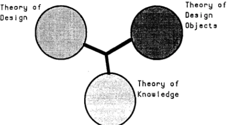
There are three ontological aspects of design: pro- cesses, models, and activities. This implies that we need theories corresponding to each aspect. A theory of CAD
is basically a union of the following three theories (cf. Fig.
4):
Advanced CAD environments 135
T h e o r y o f Des i gn
~j e c t s
Fig. 4. Theory of CAD as an aggregate of three theories.
0
0
0
3.1
Theory of design. A theory that describes the design
processes and activities.
Theory of design objects. A theory that deals with the models of design objects. For our purposes, this should be a theory of machines; in VLSI design it would be a theory of VLSI, and so on.
Theory of knowledge. A metalevel theory to describe our knowledge about design.
Design theory and logic
Usually, a design process is regarded as a mapping (cf. Fig. 3) from the function space onto the attribute
Both spaces are defined on an entity set. A design process is an evolution process about a metamodel. A metamodel
is a set of attributive descriptions of a design entity. During design, new attribute descriptions will be added, or existing ones will be modified, and the metamodel will converge to the design solution. In other words, design specifications will initially be presented in functional terms and the design will be completed when all relevant attributes of the design object are determined so as to be able to manufacture it.
A simplified view of design is then as follows. A
sequence of metamodels is generated from an initial specification and is detailed. If they cannot pass a feasibility check, then a compromise is made or back- tracking is applied. Note that the models derived from metamodels are in the meantime evaluated for con- sistency. We thus have :
Specification. s = T o +.
..
.
-+ T" +. . .
+ TN = g Metamodel. M o +.. . .
-+ M" -+. . .
-+ MN Propositions. qo +..
. .
+. q, -+. .
.
-+ qNIn this scheme, s is the original design specification and g is the design goal. Each design step has a n associated set of propositions which are denoted by q,. Two central concerns here are (i) how to choose q, (i.e. how to proceed with design) and (ii) what if we discover 1 qn (i.e.
how to deal with contradictions). We define a few other things :
where each pi is an atomic fact concerning the meta- model,
q n = PO A P I A
...
A P kCn
q n E m n
where t- is the syntactic turnstile as usual in proof theory, m n is a model, and C, is the control knowledge, and
q",mnl-r
where
D n
is the detailing knowledge and r is a proposition which should be added to q, to arrive at the nextdescription, q,+l. Knowledge appearing above the syn- tactic turnstile is used in the derivations as meta- knowledge. With this notation, the following partial classification of design can be made :
D"
Invention. Given s, find q,, C,, D,, and g.
New product development. Given s and C,, find q,, Routine design. Given s, C,, and
D,,
find q, and g . Parametric design. Given s, q,, C,, andD,,
find g. For the temporal aspects of design, a temporal logic can be developed. Let tap denote that p holds after time point t and tpp denote that p holds before time point t ;[tl, t2] denotes a time interval. Then:
D n ,
and g .ta - p = 1 ( f a p )
t x ( p v q ) = tap v taq
tar@ A q) = tap A taq
rlel
[t,, t J a p = t , ap A t,pp A t , < t ,
Using this temporal logic, we can describe inference control for production rule systems in a more explicit way. For example, in Prolog the order of rules matters. In general, this knowledge is embedded in the interpreter of the language. By disclosing this control we may introduce suppler control. For example, the detailing knowledge
D,
introduced above may be a set of rules of the following sort:t , q , A t,aq, A t , < t2
=
t,aq?t , aq, A t, aq, A t , > t ,
=
t , aq,These two formulas should be read as follows. If q1 holds after t , , q2 holds after t,, and t , is earlier than t,, then a new property, q3, holds after t,. Otherwise (i.e. t , is later than t , ) another property, q4, holds. Applications of temporal logic to design process representation should now be manifest.
Intuitionistic logic can be blended with temporal logic. Let t , ap
=
true. Now, introducing a logical symbol136 Varol Akniaii
F u n c t i o n a l G e o m e t r i c a l F i n i t e Cost flna
I
y a i 3S p e c i f i cat i o n n o d e I E I ements node I n o d e I
Dea i g n
’
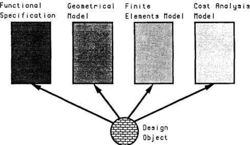
Object Fig. 5. The multiworld mechanism. unknown, we can formalize intuitionism in terms oftemporality:
t,B(p v l p )
=
unknown t,a@ v ~ p )=
trueHere p is a property that we are trying to prove about the current design object or design process.
The reader is referred to Refs 1, 2, 4-6 and 34 for
detailed coverage of the usage of these and other nonstandard logics in design.
3.2 A multiworld mechanism
During the course of design, it is of vital importance that a system allows the designer to represent the design object in various ways. These various descriptions are called models of the design object. Four such models are (cf. Fig. 5):
functional specification of the design object in terms
of the constraints that should be met;
a geometrical model that creates a visual rep- resentation of the design object (this is something that current CAD systems know rather well); a finite elements model enabling strength predictions to be made on complex mechanical constructions ; 0 a cost analysis model to calculate the manufacturing
costs.
Models are able to communicate with each other by means of a metamodel. A metamodel is a central description of the design object to w h c h all models refer and depend on. All changes that occur in a certain model are propagated through the metamodel to all other models which are then updated appropriately.
This is achieved by a special construct, the muftiworld mechanism. A model is created by a call to a design
scenario which in turn opens a world. A world is
a
part of the design object description together with some information that belongs to the particular model that is created. The multiworld mechanism lets the designer open several worlds simultaneously; in other words, several models may be active at the same time. Forexample, the designer may input new constraints and examine the results of these in a CSG model and a finite elements model.
Moreover, the multiworld mechanism allows the designer to create multiple descriptions of the design object in parallel. Here we make a distinction between dependent vs. independent worlds. Dependent worlds result in a unique design object description; they reflect the same metamodel. Independent worlds, however, can result in different design object descriptions; they do not reflect the same metamodel. In a nutshell, dependent worlds are used to create multiple views of the design object while independent worlds give rise to alternative design solutions.
In design, it must be possible to derive, in different situations, both p and l p (where p may be a logical formula). In fact, we never believe p and - p at the same time, for we would have an inconsistent theory of the world in that case. On the other hand, we may believe p and - p at different times or contexts. The multiworld
mechanism allows us to build theories that are consistent inside a context while two contexts may contain contradictory information; i.e. a multicontext frame- work helps a designer build theories that are locally consistent but globall-v inconsistent during an inter-
mediate phase of the design. Furthermore, this multi- context framework is based on the assumption that the user must be able to place the right assertions into the right context at the right level. Hence, the system acts only as a designer’s apprentice; cf. Section 2.1.
Advanced C A D environments 137
Scenarios specify how many worlds exist simul- taneously and how they relate to each other. Special care is taken for constructs that close or update a world, thereby transferring some of its properties to the metamodel. This control mechanism also checks the validity of the worlds with respect to the metamodel and propagates changes in the metamodel to all applicable worlds.
4 NAIVE PHYSICS AND MACHINE DESIGN
As the reader will recall from Section 1 (viz. Minsky’s comment), in machine design it is not yet precisely known in which symbolism one should describe the functions of machines. There is, however, a view that functions can be represented in terms of the physical phenomena that the machine exhibit^.^ Regarding this point of view, the representation of functions can be reduced to the representation of physical phenomena and qualitative reasoning about them. Minsky explains this:22
When a particular machine is described to us, we do not first ask questions about its material construction. Given an engineering drawing, a circuit diagram, a patent description-something must first convince us that we understand how it works in principle. That is, we must see how it is ‘supposed’ to work. We inquire only later whether this member will stand the stress, or whether that oscillator is stable under load, etc. But the idea of a machine centers around some abstract model or process.
In qualitative physics, the reduction of information is arrived at by creating an abstract layer which may, strictly speaking, be incorrect but sufficiently correct for the problem at hand. Naive physics observes that people have a different kind of knowledge about the physical world. This knowledge can best be described as common
sense and is attained after years of interaction with the world. Accordingly, naive physics ideas are useful in machine design and we want to codify them. To this end, we follow the manifesto of Ref. 18 and hope to capture naive physics in logic. Additionally, we use qualitative
reasoning as a mathematical tool; this is explained below.
Consider the following concepts underlying change in physical systems : state, cause, equilibrium, oscillation, force, feedback, etc. Naive physics regards these concepts in a simple qualitative way. It maps continuous variables to discrete variables taking only a small number of values (e.g.
+,
- , and 0). Accordingly, differential equations are mapped to qualitative differential equations which are also known as confluences. Consider the simple pressure regulation in Fig. 6 . The confluenceSP+6A-SQ = 0
describes this device in qualitative terms. Here
P
is the pressure across the valve, A is the area available for flow,and Q is the flow through the valve; 6 means change. Let
us look at the way the regulator works. An
t
in pressure at a-
ant
in pressure at b-
ant
in flow through b=-
an .f in pressure at d*
diaphragm at e pushes downward=> valve at b tightens
*
an.1
in area for flow=-
a3.
in flow through b. Thus the regulator maintains constant pressure at c in spite of fluctuations at the supply side a. Note that if the valve is closed (i.e. SA = SQ = 0 ) , then itis predicted that P is constant. The correct confluence for this state should instead read SQ = 0; we simply do not say anything about
P.
We have to admit that when one speaks of machine design, mechanism (interconnected links and joints) design should also be considered. Mechanism design represents the foundation of a large percentage of the entire field of machine design. Also, it is probably more complex than other types of mechanical design (i.e. static components). There is not much useful work yet regarding the qualitative analysis of mechanisms.
The use of qualitative reasoning facilitates the analysis of the working of physical devices. This may not be without a price. Qualitative techniques may cause ambiguities. Assume that a certain quantity M varies
with N,/N,, i.e. M a N , / N , . If N ,
t
while N, remains constant thenM
alsot.
However, we cannot reason without a finer knowledge of the individual changes when we are told that both N , and N ,1
(or J). The techniques of order of magnitude reasoning are designed to handle precisely this kind of problem without requiring knowledge of the numerical values involved.In the pressure regulator example, we are employing a powerful principle in our reasoning, viz. the mechanisric world view. This asserts that every physical situation is regarded as a device made up of individual components, each contributing to the overall behavior. Nevertheless, the laws of the substructures may not presume the functioning of the whole-the principle of no-function-in-
structure.” Additionally, assumptions that are specific to
a particular device should be distinguished from the
class-wide assumptions which are common to the entire
class of devices. A simplistic view of modeling devices comprises three kinds of constituents : materials (e.g. oil, air), components (e.g. shafts, wheels), and channels (e.g. water pipes, electric cables).
After modeling a device we can reason about it. In
envisionment we start with a structural description to
determine all possible behavioral sequences. Thus, in envisioning, we momentarily forget about the real values of the problem variables and try to see all possible outcomes of some action.‘*
Naive physics concepts are required for design because a design object will have a physical existence and,
138 Varol Akman
accordingly, obey natural laws. If we want to create designs corresponding to physically realizable design objects then we will have to refer to naive physics notions such as solids, space, motion, etc. Furthermore, if we want to reason about a design object in its destined environment we will need naive physics procedures such as envisioning, simulation, and diagnostics.
Caveat. Naive physics might be sufficiently correct for use in describing (to some level of accuracy) some physical phenomena, but this is a different matter from using naive physics to design real world objects, where it is much harder to know a priori what level of correctness is required. Design usually assumes that a high accuracy is obligatory and that the best representations of natural laws are requisite. That is why we use Newtonian mechanics for example, rather than something like Aristotelian mechanics, which might seem more intuitive to a naive physicist. It is one thing to use naive physics notions to predict what might happen in some physical system; it is quite another to use them to determine how to get something to happen in a physical system.
5 DESIGN AND CAUSALITY
About thirty years ago, John McCarthy wrote a landmark paper titled ‘Programs with common sense’.’l According to McCarthy, a program is said to possess common sense if it automatically deduces for itself a sufficiently wide class of immediate consequences of anything it is told and what it already knows. A proposal along these lines (called ADVICE TAKER) was made in the same article and some conceptual examples were given.
Causality is an important ingredient of commonsense reasoning. The design solution space can be construed as a large (infinite) set of potential solutions bounded by an increasingly specific set of design constraints. The constraints come either from the problem definition (i.e.
requirements) or from actions describing a proposed solution (i.e. design decisions). In general, the constraints are stated in terms of design variables. With this picture in mind, the role of causation in design can be easily seen.*’ As the value of a design variable is changed to reflect a design decision, it has the inherent capacity to cause a series of ‘ripple’ effects. Thus, we intend to reflect, using the word causation, the nature of a design problem in which changes to one set of variables cause changes to occur in others. Accordingly, design can be seen as the process of deciding how an existing (unfinished) design proposal would react to a particular modification or how a desired effect can be realized within the given constraints. Therefore, we need a dependency structure on the design problem that we can make effective use of in determining the cause and effect of alternative design decisions. This dependency struc- ture gives us the means to understand the problem without actually having to make changes. Obviously, such dependency structures are what essentially con- stitute a n ‘envisionment’ program (cf. Section 4) and this is another reason why naive physics must be an integral part of intelligent design systems.
ACKNOWLEDGMENTS
The author would like to thank Paul ten Hagen (Centrum voor Wiskunde en Inforrnatica, Amsterdam) and Tetsuo Tomiyama (The University of Tokyo) for their in- tellectual support and is grateful to the Guest Editor of this issue for the invitation to submit an article and suggesting ‘ Intelligent CAD’8 as a possible topic.
REFERENCES
1. Akman, V.. Formal methods for intelligent CAD. In
Proceedings of International Conference on CAD and CG,
ed. L. Yongchun, H. Gang & Y. Xia. International Aca- demic Publishers, Beijing, China, 1989, pp. 316-21.
2. Akman, V., Modalities for design models (Research Review). Art8cial Intelligence for Engineering Design, Analysis, and Manufacturing, 4 ( 2 ) (1990) 130-1.
3. Akman, V. & ten Hagen, P., The power of physical representations. AZ Magazine, 10 (3) (1989) 49-65. 4. Akman, V. & Tin, E., Computational models of design
(Short Note). American Association for Artificial Intel-
ligence (AAAI) Special Interest Group in Manufacturing (SZGMAN) Newsletter, 3 (1) (1990) 2-3.
5. Akman, V. & Tomiyama, T., The role of logic and commonsense reasoning in intelligent CAD. In Proceedings
of Third IFIP W.G. 5.2 Workshop on Intelligent CAD,
Osaka, Japan, 1989, pp. 15-20.
6. b a n , V., ten Hagen, P., Rogier, J. & Veerkamp, P., Knowledge engineering in design. Knowledge-Based
Advanced CAD environments 139
7. Akman, V., ten Hagen, P. & Tomiyama, T., A fundamental and theoretical framework for an intelligent CAD system.
Computer-Aided Design, 22 (6) (1990) 352-67.
8. Akman, V., ten Hagen, P. J. W. & Veerkamp, P. (eds),
Intelligent CAD Systems I I : Implementational Issues.
Springer-Verlag, Berlin, 1989.
9. Barwise, J., The Situation in Logic. CSLI Lecture Notes Number 17, Center for the Study of Language and Information, Stanford, Calif., 1989.
10. Barwise, J. & Perry, J., Situations and Attitudes. MIT Press,
Cambridge, Mass., 1986.
11. Bobrow, D., Mittal, S. & Stefik, M., Expert systems: perils . and promise. Communications of the A C M , 29 (1986) 880-94.
12. Brown, D. & Chandrasekaran, B., Knowledge and control for a mechanical design expert system. IEEE Computer, 19 13. Coyne, R., Logic Models of Design. Pitman, London, 1988. 14. de Kleer, J., Qualitative and quantitative knowledge in classical mechanics. Technical Report AI-TR-352, Massa- chusetts Institute of Technology, Cambridge, Mass., 1975. 15. de Kleer, J. & Brown, J., A qualitative physics based on
confluences. Artificial Intelligence, 24 (1984) 7-83. 16. Dyer, M., Flowers, M. & Hodges, J., EDISON: an
engineering design invention system operating naively.
Artificial Intelligence in Engineering, 1 (1) ( I 986) 36-44. 17. Fishwick, P. & Zeigler, B., Qualitative physics: towards the
automation of systems problem solving. In Proceedings of the A I , Simulation, and Planning Workshop in High Autonomy Systems. IEEE Computer Society Press, 1990,
18. Hayes, P., The second naive physics manifesto. In Formal
Theories of the Commonsense World, ed. J. Hobbs & R. Moore. Ablex, Norwood, New Jersey, 1985, pp. 1-36. 19. Kowalik, J. (ed.), Coupling Symbolic and Numerical
Computing in Expert Systems. Elsevier Applied Science
Publishers, Amsterdam, 1986.
20. Levesque, H., The logic of incomplete knowledge bases. In On Conceptual Modeling, ed. M. Brodie, J. Mylopoulos &
J. Schmidt. Springer-Verlag, New York, 1984, pp. 165-86. (7) (1986) 92-100.
pp. 117-34.
21. McCarthy, J., Programs with common sense. In Semantic
Information Processing, ed. M. Minsky. MIT Press,
cambridge, Mass., 1968, pp. 403-18.
22. Minsky, M., Computation : Finite and Infinite Machines.
Prentice-Hall, Englewood Cliffs, New Jersey, 1967. 23. Mittal, S., Dym, C. & Morjaria, M., PRIDE: an expert
system for the design of paper handling systems. IEEE
Computer, 19 (7) (1986) 102-14.
24. Mostow, J., Toward better models of the design process.
A I Magazine, 6 (1) (1985) 44-57.
25. Negroponte, N., The Architecture Machine (Toward a
More Human Environment). MIT Press, Cambridge, Mass.,
1970.
26. Newell, A. & Simon, H., Human Problem Solving. Prentice- Hall, Englewood Cliffs, New Jersey, 1972.
27. Newton, S . & Logan, B. S., Causation and its effect: the blackguard in CAD’S clothing. Design Studies, 9 (4) (1988) 1 9 6 2 0 1.
28. Purcell, P. A., Computer environments for design and designers. Design Studies, 9 (3) (1988) 144-9.
29. Schon, D. A., Designing: rules, types, and worlds. Design
Studies, 9 (3) (1988) 181-90.
30. Simon, H., The structure of ill-structured problems. In
Models of Discovery (and Orher Topics in the Methods of Science), D. Reidel, Dordrecht, 1977, pp. 30&25. 31. Simon, H., The science of design: creating the artificial. In
The Sciences of the Artificial, MIT Press, Cambridge,
Mass., 1979, pp. 55-83.
32. Sutherland, I., SKETCHPAD : a man-machine graphical communication system. In Proceedings of the AFIPS Spring Joint Computer Conference. Spartan Books, Balti-
more, Md., 1963, pp. 32946.
33. Tomiyama, T. & Yoshikawa, H., Extended general design theory. Technical Report CS-R8604, Center for Math- ematics and Computer Science, Amsterdam, 1986. 34. Veerkamp, P. J., Bernus, P., ten Hagen, P. J. W. & Akman,
V., IDDL: a language for intelligent, interactive, integrated CAD systems. Technical Report CS-R9056, Center for Mathematics and Computer Science, Amsterdam, 1990. 35. Yeomans, R., Choudry, A. & ten Hagen, P., Design Rules