T.C.
DİCLE ÜNİVERSİTESİ FEN BİLİMLERİ ENSTİTÜSÜ
GEOSENTETİK DONATILI İSTİNAT DUVARLARININ SONLU ELEMANLAR YÖNTEMİ İLE SAYISAL ANALİZİ
Husen Ghazi Fathe BAJLAN
YÜKSEK LİSANS TEZİ
İNŞAAT MÜHENDİSLİĞİ ANABİLİM DALI
Danışman: Doç. Dr. M. Salih KESKİN
DİYARBAKIR Haziran-2016
INSTITUTE OF NATURAL AND APPLIED SCIENCES
NUMERICAL ANALYSIS OF GEOSYNTHETIC REINFORCED EARTH WALLS WITH FINITE ELEMENT METHOD
Husen Ghazi Fathe BAJLAN
MASTER THESIS
DEPARTMENT OF CIVIL ENGINEERING
Supervisor: Assoc. Prof. Dr. M. Salih KESKİN
DIYARBAKIR June - 2016
APPROVAL OF THE THESIS
UNIVERSITY OF DICLE
INSTITUTE OF NATURAL AND APPLIED SCIENCES DIYARBAKIR
“Numerıcal Analysıs of Geosynthetıc Reınforced Earth Walls wıth Fınıte Element Method” SUBMITTED by Husen Ghazi Fathe BAJLAN in partial
fulfillment of the requirements for the degree of Master of Science in Civil Engineering.
Examination Committee:
Title Name & Surname Signature
Chairman (Supervisor): ………..
Member :……….
Member :……….
Date of Thesis Defense: / /2016
I approve accuracy of the above information. Assoc. Prof. Dr. Mehmet YILDIRIM
MANAGER OF THE INSTITUTE (2016)
I
ACKNOWLEDGEMENTS
At first I would like to thank Allah for that this thesis completed at the proper quality and proper time. Then I would like to express my sincere gratitude to my supervisor, Assoc. Prof. Dr. MEHMET SALIH KESKIN for his helpful suggestions, guidance and understanding that he provided throughout the preparation of this thesis. I am also very grateful to Assoc. Prof. Dr. TAHA TASKIRAN for his useful instruction within and outside of this study and provided valuable discussions and guidance.
I am thankful to Diyarbakir State, DICLE UNIVERSITY for giving me this great opportunity to become a part of it, and to obtainment the degree of Master of Science. I also wish to thank all faculty staff and the other graduate students at the Engineering faculty for their valuable assistance, support, friendship and encouragement.
I am indebted to my mother, father and two brothers for their unconditional moral support, encouragement and love. I also wish success for my brothers in their life. Finally, I would like to express my special thanks my family.
II
TABLE OF CONTENTS
ACKNOWLEDGEMENTS……… I
TABLE OF CONTENTS……….………...… II LIST OF FIGURES………..………..……… IV LISTOFTABLES……….. VIII LISTOFAPPENDIX………. IX ABSTRACT………...…… X
OZET……….. XII
1. CHAPTERONE:INTRODUCTION………...………..…………. 1
1.1. INTRODUCTION... 1
1.2. PROBLEM STATEMENT……….……….………….. 2
1.3. OBJECTIVE OF THESIS... 2
1.4. REVIEW OF PREVIOUS WORK……….. 2
1.5. THESIS OUTLINE………..……… 7
2. CHAPTERTWO:REINFORCEDRETAININGWALLS………….. 9
2.1. INTRODUCTION………... 9
2.2. DEFINITION……….………. 11
2.3. TYPESOFRETAININGSOILWALLS……… 11
2.4. PURPOSES OF REINFORCED RETAINING SOIL WALLS……... 13
2.5. MAIN PARTS OF REINFORCED RETAINING SOIL WALLS………. 13
2.6. REINFORCED RETAINING SOIL WALL CRITERIA………….. 14
2.7. REINFORCED RETAINING SOIL WALL FAILURE………. 15
2.7.1 External Failure……….. 16
2.7.2 Internal Failure……… 16
3. CHAPTERTHREE:METHOLOLOGY……… 18
3.1 INTRODUCTION………... 18
3.2 MATERIALS (GEOSYNTHETIC)……….………..………….. 18
3.2.1. Geotextile………. 21
3.2.2. Geogrid………. 21
3.3 FINITE ELEMENT METHOD………..…………. 25
III 3.4.1 General Model……….. 26 3.4.2 Mesh generation……….. 27 3.4.3 Boundary conditions……….. 28 3.4.4 Initial conditions………. 28 3.5 PLAXIS PROGRAM………..……... 29
4. CHAPTERFOUR:RESULTSANDDISCUSSION……..……..…….. 31
4.1. Introduction………... 31
4.2. Unreinforced Soil Wall Analysis……… 32
4.3. Effect of Length Of Reinforcements And Vertical Spacing………. 33
4.4. Effect of Thickness Of Concrete Facing Wall……… 34
4.5. Effect of Embedment Of Wall………... 35
4.6. Effect of Surcharge Load……….. 36
4.7. Effect of Ground Water... 37
4.8. Effect Of Surface Water Table………... 40
4.9. Effect Of Reinforcement Stiffness………... 42
5. CHAPTERFIVE:CONCLUSIONSANDRECOMMONDATIONS.. 49
REFERENCES……… 51
IV
LIST OF FIGURES
Figure No Page No
Figure 1.1. Distribution of vertical foundation pressure for different height
above the first reinforcement layer during construction. . . 3
Figure 1.2. Lateral earth pressures along wall height. . . . . 3
Figure 1.3. Potential slide surface of the wall. . . 4
Figure 1.4. Effects of reinforcement spacing on lateral deformation of reinforced soil zone………
6
Figure 1.5. Offset distance effect on reinforcement that’s required for factor of safety equals to 1.5………
7
Figure 2.1. A simple illustration of Geosynthetic-Reinforced Segmental
retaining wall. . . 8
Figure 2.2. GRS-RW typical section drawing. . . . . . . 9
Figure 2.3. Construction process of a Geosynthetic-Reinforced Soil Structure. . 9
Figure 2.4. The principal elements of a GRS-RW. . . . . . .
13
Figure 2.6. Potential external failure mechanisms of MSE structures. . .
15
Figure 2.7. Internal failure mechanisms of MSE structures. . . 16
Figure 2.8. Potential modes of failure: external (top row); internal (middle
row); facing (bottom row). . . . . . 17
Figure 3.1. Main concept of reinforced earth. . . 20
V
Figure 3.2b. Two directions (biaxial) geogrid. . . 22
Figure 3.3. Typical geosynthetic materials types. . . 23 Figure 3.4. Interaction mechanisms in a geosynthetic reinforced soil wall. . . . 24
Figure 3.5. The 15-node element as used in PLAXIS with degrees of freedoms and nodal forces. . . 25
Figure 3.6. Local numbering and positioning of nodes………. 27
Figure 3.7. Model of reinforced soil retaining wall………. 27
Figure 3.8. The geometry of the finite element model. . . 28
Figure 4.1. Geogrid reinforced soil retaining wall model. . . . . 31
Figure 4.2. Factor of safety against height of wall for unreinforced case. . . . . 32
Figure 4.3. Displacement against height of wall for unreinforced case. . . 32
Figure 4.4a. Effect of reinforcement length and geogrid spacing on the factor of safety. . . . . . . . . . . . . . . . . . . 33
Figure 4.4b. Effect of reinforcement length and geogrid spacing on the factor of safety. . . . . . . . . . . . . . . . . . . 34
Figure 4.5. Effect of geogrid length and vertical spacing on the wall displacement. ……… 34
VI
Figure 4.7. Effect of thickness of concrete facing wall on displacement. . . . . 35
Figure 4.8. Effect of embedment of the wall on factor of safety. . . . . . . . . . 36
Figure 4.9. Effect of embedment of the wall on displacement. . . . . . . . . . . 36
Figure 4.10. Effect of Surcharge on factor of safety. . . . . . . . . . . . . . . . . . 37
Figure 4.11. Effect of Surcharge on displacement. . . . . . . . . . . . . . . . . . . . 37
Figure 4.12. Variable levels of ground water. . . . . . . . . . . . . . . . . . . . . . . 38
Figure 4.13. Effect of Ground water on factor of safety. . . . . . . . . . . . . . . . 39
Figure 4.14. Effect of ground water on the displacement. . . . . . . . . . . . . . . . 39
Figure 4.15. Effect of ground water on the active pore pressure. . . . . . . . . . . 40
Figure 4.16. Effect of surface water on factor of safety. . . . . . . . . . . . . . . . . 41
Figure 4.17. Effect of surface water on the displacement. . . . . . . . . . . . . . . 41
Figure 4.18. Effect of surface water on the active pore pressure. . . . . . . . . . . . 42
Figure 4.19. Effect of reinforcement stiffness E on the factor of safety. . . . . . . 43
Figure 4.20. Effect of reinforcement stiffness E on displacement. . . . . . . . . . . 43
Figure 4.21. Effect of reinforcement stiffness on total displacement increments. 44
Figure 4.22. Effect of reinforcement stiffness on extreme axial force of geogrid.. 44
VII
Figure 4.24. Total displacement increments of geogrid (mm) along wall height. . 45
Figure 4.25. Extreme total displacements (E=1000 kN/m). . . . . . . . . . . . . . . . 46
VIII
LIST OF TABLES
Table No Page No
Table 2.1. Minimum factors of safety. . . . . . . . . . . 15
Table 2.2. Recommended minimum factors of safety with respect to
failure modes……… 18
Table 3.1. Material properties of the foundation soil and granular backfill soil. . 30
Table 3.2. Values of plate properties used in analysis. . . . 30
IX
LIST OF APPENDIX A
Figure No Page No
A.1. Deformed Mesh for Stiffness E= 1000 kN/m……… 53
A.2. Total displacements (Arrows) for Stiffness E= 1000 kN/m…… 53
A.3. Total displacements (contour lines) for Stiffness E= 1000
kN/m... 54
A.4. Deformed Mesh (shadings) for stiffness E= 1000 kN/m……….. 54
A.5. Deformed Mesh for stiffness E= 100 000 kN/m………….…… 55
A.6. Total displacements (Arrows) for Stiffness E= 100 000 kN/m… 55
A.7. Total displacements (contour lines) for Stiffness E= 100000
kN/m……… 56
A.8. Deformed Mesh (shadings) for stiffness E= 100 000 kN/m …... 56
X ABSTRACT
NUMERICAL ANALYSIS OF GEOSYNTHETIC REINFORCED EARTH WALLS WITH FINITE ELEMENT METHOD
M.SC. THESIS Husen Ghazi Fathe BAJLAN
UNIVERSITY OF DICLE
INSTITUTE OF NATURAL AND APPLIED SCIENCES DEPARTMENT OF CIVIL ENGINEERING
2016
Geosynthetic reinforced soil retaining walls (GRSRW), is in a period of vast development. The construction of geosynthetic-reinforced soil retaining walls is becoming widespread, and took acceptance has extended throughout the world, because of its aesthetic value and ease of construction. GRSRW have become a significant presentation of retaining structures. Several studies expose that the use of geogrid as an addition increases the stability of slopes and structures.
The objective of this thesis is to study the behavior of geogrid reinforced earth retaining walls. Likewise, to analysis the parameters and geometry effects on the performance of a geogrid reinforced soil retaining wall such as length of reinforcement, vertical distances between reinforcement layers, thickness of the facing concrete wall, embedment of facing wall, surcharge, ground water level, surface water table and effect of reinforcement stiffness. PLAXIS 2D finite element program was adopted to perform the analyses.
Results show the following: 1) Maximum height soil wall can be constructing without reinforcement and without surcharge is 2.9m. 2) Increase length of reinforcement (L) has a significant effect on improving behaviors of soil wall. Whereas the vertical spacing between reinforcement layers (h) has a slight effect. 3) Adding reinforcement to soil has decrease the effect of both of the facing wall thickness (t) and embedment depth (d). 4) Adding reinforcement to soil has increase soil bearing capacity
XI
to carry a massive surcharge loads. 5) GRSRW was unaffected by the change in water ground level and surface water table, whereas unreinforced soil wall, with the height of 2.9m, was collapsed with this change. 6) Increasing reinforcement stiffness led to improve soil behavior i.e. decreasing the wall lateral displacement, until reach optimum value. For the model of this study the optimum value was (E= 20 000 kN/m).
Key words: Retaining walls, Geogrid, PLAXIS, Finite Element Method, Factor of Safety
XII ÖZET
GEOSENTETİK DONATILI İSTİNAT DUVARLARININ SONLU ELEMANLAR YÖNTEMİ İLE SAYISAL ANALİZİ
YÜKSEK LİSANS TEZİ Husen Ghazi Fathe BAJLAN
DİCLE ÜNİVERSİTESİ FEN BİLİMLERİ ENSTİTÜSÜ
İNŞAAT MÜHENDİSLİĞİ ANABİLİM DALI 2016
Geosentetik donatılı istinat duvarları günümüzde hızlı bir gelişim içerisindedirler. Geosentetik donatılı istinat duvarları, estetik görünümleri ve yapım kolaylığı avantajlarından dolayı tüm dünyada geniş bir şekilde kullanım alanı bulmaktadır. Bir çok çalışmada, geogrid kullanılarak şevin ve istinat yapısının stabilitesinin arttığı belirlenmiştir.
Bu tez çalışmasının amacı, geogrid donatılı istinat yapılarının davranışının sayısal olarak incelenmesidir. Bu amaçla; donatı uzunluğu, donatılar arası mesafe, istinat duvarının kalınlığı, istinat duvarının gömülme derinliği, sürşarj yükü, yer altı su seviyesi ve donatı rijitliği parametrelerinin, geogrid donatılı istinat duvarlarının performansı üzerindeki etkileri araştırılmıştır. Analizler, PLAXIS 2D sonlu elemanlar programı kullanılarak gerçekleştirilmiştir.
Çalışma sonunda elde edilen sonuçlara göre: 1) Donatı ve sürşarj yükü olmadan inşa edilebilecek en büyük duvar yüksekliği 2.9m. olmaktadır. 2) Donatı uzunluğu (L) değerinin arttırılması duvar davranışı üzerinde önemli bir etkisi olmakla birlikte, donatılar arası düşey mesafenin etkisi daha sınırlı kalmaktadır. 3) Donatılı durumda istinat duvarının kalınlığı ve gömülme derinliği azaltılabilmektedir. 4) Donatılı durumda zemin taşıma gücü artmakta ve büyük sürşarj yükleri taşınabilmektedir. 5) Geosentetik
XIII
donatılı istinat duvarlarında temel zeminindeki suyun etkisinden dolayı stabilite kaybı yaşanmazken donatısız durumda stabilite kaybı yaşanmaktadır. 6) Donatı rijitliğinin belli bir değere kadar artması zemin davranışını iyileştirmekte duvarın yanal deplasmanlarını azaltmaktadır. Bu modelde optimum rijitlik değeri E= 20 000 kN/m olarak elde edilmiştir.
Anahtar Kelimeler: İstinat duvarı, Geogrid, PLAXIS, Sonlu Elemanlar Yöntemi, Güvenlik Sayısı
1
CHAPTER ONE
INTRODUCTION
1.1 INTRODUCTION
One of most generally method for improving mechanical behaviors of soil is to use reinforcement. The weak tensile strength of soil can be increased by adding reinforcement. Thus, the new composition of soil and reinforcement gives anew-stronger results, which can bear large loads. Reinforcement avoids lateral pressure. In addition, reinforcement will increase the strength of soil mass. Reinforcement in general acting in soil by increasing lateral angle of friction in low stresses and increase cohesive for high stresses. Retaining walls are main element for design roads. Retaining structures used for bridge’s abatements and wing walls for slope stability and right of road. At the near past retaining walls was made by reinforced concrete as two type either gravity walls or cantilever walls. Nevertheless, it was unable to carry a big magnitude of differential settlements when height of wall of embankment increased, and lies on weak foundation, the cost of reinforced concrete wall will increase rapidly. The cost of construction is meaning many thinks like wall volume, type of foundation, type of wall, cut, fill and face finishing. A rate of 25%-50% of cost will be save, if reinforced soil used instead of the conventional concrete retaining walls, especially for heights that more than 3m and with soft soil underlies foundations [17], [15].
Henri Vidal (1960) in France, invent a system that was called Reinforced Earth, used metal strips for reinforcement. From that time many types of reinforcement earth system was developed in Europe and United State. They offered many system to be alternative to the conventional retaining walls, such as stable retaining walls, natural or engineered slopes. From that time there is no stander system for design of reinforced earth? There is some various design and criteria and procedures for each design, but they are all have a different performance, different records. High way and civil engineering departments, they don’t have accepted methods to evaluate the different systems, and determine which of those systems are agreed with technique limits for the project [15].
CHAPTER ONE INTRODUCTION
1.2 PROBLEM STATEMENT
There are no specifications, standards nor guides for how to use soil reinforcement with retaining walls. There is need to know the influence of the reinforcement parameters and soil parameters on the behavior and stability of the reinforced soil. Which are the following factors: Space between reinforcement layers, number of reinforcement layers, length of the reinforcement, strength of the reinforcement, and soil condition of backfill, height of the retaining wall, thickness of the wall, foundation depth, effect of surcharge and dynamic conditions.
1.3 OBJECTIVE OF THESIS
The aim of this thesis is to find out the influence of the reinforcement and soil parameters on the behavior and stability of the reinforced retaining wall, for purpose of providing a study to be use as an initial guide for design of reinforced retaining walls. The study will be done by using numerical analysis and finite elements method to simulate the soil-reinforced retaining wall in two dimensional model by using Plaxis 8x software.
1.4 REVIEW OF PREVIOUS WORKS
Astarcı (2008) has studied the friction between many kinds of geosynthetic reinforcements, which are used in geosynthetic reinforced earth retaining walls and dry-stacked concrete blocks, by comparing the friction properties between three types of polymer geosynthetic reinforcements with each other, using empty dry stacked concrete blocks, sand and gravel, are used as infill in the tests. He calculated and recorded the angle of friction for all case. Moreover, he evaluated the results comparatively [3].
Yang et al., (2009) used monitoring during construction of a geogrid reinforced soil retaining wall for railway in China, for inspecting the behaviors of the wall. The vertical foundation pressure of reinforced soil along the reinforcement length is non-linear, and the ultimate value is at the middle range of length of reinforcement, figure 1.1 [29].
3
Figure 1.1. Distribution of vertical foundation pressure for different height above the first reinforcement layer during construction [29].
The horizontal earth pressure is non-linear along the height of reinforced soil and the active lateral earth pressure value is greater than the earth pressure figure (1.2) [29].
CHAPTER ONE INTRODUCTION
The potential failure plane at position of lower of the wall is closer to the active Rankine earth pressure theory while the potential failure plane at position of upper of wall is similar to ‘‘0.3H method’’, figure (1.3) [29].
Figure 1.3. Potential slide surface of the wall [29].
Abioghli (2011) has studied the behavior of geosynthetic reinforced soil walls by the numerical method with PLAXIS program. His results shows that the long reinforcement with less distance in the top of wall can be use and short reinforcement at the bottom of wall can be put. So design an economical and less consumption can be achieved [2].
Ali and Hai (2011) in their paper a parametric study using a finite elements method are conducted and a numerical simulation of a reinforced soil wall construction was described to study the behavior of the wall during and after construction. Their results appeared that when the wall can move laterally the horizontal pressures at the connection began to increase with the depth of fill until reached a sixth height of wall (0.6 H). After 0.6 H, it reduced for further depth. But if there is no lateral movement, the line of horizontal pressure follow the Ko (at rest) line until reached a depth of 0.6 H. Under 0.6 H, the horizontal pressure drops rapidly. When the compressibility of the soil increased it makes redistribution of in the reinforcements at lower levels and smaller at 0.6 H depth of fill [4].
5
Ehrlich et al., (2012) presented a laboratory model to investigate the effect of compaction on the geogrid reinforced soil walls behaviors. A vibrating plate and a vibratory tamper were used for soil compaction. Equivalent vertical stresses for the vibrating plate were much lower than the corresponding value of the vibratory tamper. Monitoring system was used for observation the external and internal wall displacements and mobilized tension along the reinforcements. The result showed that along with a reduction of the void ratio of soil, the soil compaction, was also increased the horizontal stress in mass of reinforced soil and generates a pre-consolidated material. Results showed that compaction has significant effective on reinforcement tensions and displacements. In addition, the results showed that with heavy compaction the maximum tensile force mobilized in the reinforcements was nearer to the wall face. Moreover, the tension measured along the reinforcement layers after end of construction, with using the light soil compaction was very less when using the heavy soil compaction. However, it was noticed that the difference in the tensions in reinforcements of the two walls decreased with increase in the external surcharge load [9].
Duijnenin et al., (2012) have studied a reinforced soil retaining wall was constructed for supporting two viaducts in Netherlands. Thy preloads the fill before installing the bridge deck to activating the deformations of the wall. Until 60 days after the installation of the bridge deck, the vertical and horizontal deformations of the earth retaining wall were measured. Comparing analysis with finite elements shows that the calculated deformations are much greater than the measured deformations. It is concluded that the fill and the reinforcement behave stiffer in reality [8].
Suksiripattanapong et al., (2012) present a numerical simulation of the bearing reinforcement soil wall by PLAXIS 2D software. The parameters for the model were obtained from laboratory. The equivalent friction resistance is represented by the soil/reinforcement interface parameter, R, which was obtained laboratory. The R values are 0.65 and 0.75 for the bearing reinforcement with 2 and 3 transverse members, respectively. The results were in good agreement with the measured ones. The simulated results show that the BRE wall behaves as a rigid body, retaining the unreinforced backfill. The simulated bearing stress presents a trapezoid distribution shape. The simulated settlement is almost uniform due to a high stiffness of the rigid
CHAPTER ONE INTRODUCTION
foundation and the bearing reinforcements. The maximum lateral movement occurs at about the mid-height of the wall [24].
Liu (2012) has used a finite element to analyze and to understand the horizontal facing displacements of Geosynthetic-Reinforced Soil (GRS) walls at the end of construction and after ten years. The study found that reinforcement spacing and reinforcement stiffness was mainly effect on horizontal facing displacement and the deformation of reinforced earth area, whereas the effect of reinforcement length was very small. The reinforcement length has a small effect to determine the displacement at the back of reinforced earth area. With constant reinforcement length, the reinforced earth area could be considered as a deep beam. The displacement at the back of reinforced earth area was determined by the beam stiffness, beam depth and earth pressure, the last of which is a function of reinforcement stiffness, reinforcement spacing, facing stiffness and soil stiffness [16].
7
Mirmoradi and Ehrlich (2013) have studied the behavior of reinforced soil walls by using a numerical analysis. The numerical approach was validated with the results of a wrapped-faced full-scale reinforced soil wall. And also, parametric studies were used by combinations of: compaction efforts, facing type, reinforcement stiffness, and shear resistance of the backfill. Results showed that for depths under which the overburden stresses are greater than the compaction stresses, the ultimate tension in the reinforcements is equal. For the wrapped faced wall, the maximum tension in the reinforcement occurred close to the bottom of the wall and for the block facing wall, the maximum values occurred near the mid-height of the wall. For both block and wrapped faced walls any increase in reinforcement stiffness means more values in the reinforcement tension and any increase in soil shear resistance led to lower of tension in the reinforcements values [18].
Yardımcı (2013) has used Plaxis 8.2 program to obtain 58 analyses for inspecting the tiered retaining walls. He found that any increasing in the length of reinforcement led to greater factor of safety and lower horizontal displacement. Increasing the offset distance between two tiers reduces the lateral displacements and increases the factor of safety. When offset distance exceeds 1.5 times the height of tier, effect of length of reinforcement on factor of safety and displacements decreased considerably. The factors of safety for the cohesive fill are greater than non-cohesive, and displacements are lower. For cohesive fill, the critical offset distance beyond which two-tiered wall behaves like two independent walls, was found as 2.25 times of the tier height (2.25H), and for non-cohesive fill, this value was (2H) [30].
Figure 1.5. offset distance effect on reinforcement that’s required for factor of safety equals to 1.5 [30].
CHAPTER ONE INTRODUCTION
Kondalamahanthy (2013) in his thesis investigated a probable variety of the residual angle of friction for the Shale Pierre. The landslide of the Forest City, which happened in the ditch of Missouri River, was the case study. The residual angles of friction are evaluated by performing a definite back analysis of the slope in two and three dimensions. The definite two-dimension analysis is achieved in limit equilibrium and finite element methods using SLOPE/W and SIGMA/W software’s from GEOSTUDIO 2007. He used CLARA/W software in order to determine three-dimensional analysis. The values, which are obtained from analyses, were compared and a reasonable value of (4o to 6.64o) is selected to represent values of the residual angle of friction for the Pierre Shale [14].
In this study, there is an investigation for the influence of the reinforcement parameters and soil parameters on the behavior and stability of the reinforced soil. Which are the following factors: space between reinforcement layers, number of reinforcement layers, length of the reinforcement, strength of the reinforcement, and soil condition of backfill, height of the retaining wall, thickness of the wall, foundation depth, effect of surcharge and dynamic conditions.
1.5 THESIS OUTLINE
This thesis is divided into five chapters and an appendix as follows: It begins with chapter one, which is general introduction, problem statement, goals of thesis, previous works. Then chapter two talks in details about reinforced soil retaining walls: introduction, definitions, types of retaining walls, purposes of reinforced retaining walls, characteristics of reinforced retaining walls, main parts of reinforced retaining walls, forces acting on the reinforced retaining wall, reinforced retaining wall criteria and reinforced retaining wall failure. While methodology is in chapter three which involves introduction, materials (geosynthetic), Mohr-Coulomb model, finite elements method, finite elements model, Plaxis program and retaining wall modeling. Chapter four is content results and discussion. The last chapter states conclusions and recommended future studies. Then references and followed by an appendix for more details in the end of thesis.
9
CHAPTER TWO
REINFORCED SOIL RETAINING WALLS
2.1 INTRODUCTION
The use of geosynthetic for purpose of reinforcement allows us to replace the heavy concrete walls by reinforced earth structures, which have advantages like; structure can be established on soft soil, also can significantly bear differential settlement. Reinforced soil can be defined as composite materials, which takes strength of two materials in order to reduce weakness of each of them. The soil materials are the compression materials, which are available cheaply and in large amounts. Whereas, tensile materials are the geosynthetic material, which is more costly relatively, but have highly tensile resistance. In result, the mutual relationship between these two materials develops the general properties for these composite materials, like the relationship between concrete and steel. When using geosynthetic as reinforcement in soil, this type of retaining walls are called geosynthetic soil retaining wall (GRS-RW), adding tensile reinforcement elements to soil, strength of soil will significantly improve; also, facing system will prevent emigration of soil particles from backfill. This makes the great inclined slops and vertical walls to construct in safety. A simple example for the segmental retaining walls can be seen in figure 2.1. While figure 2.2 shows a typical section [28], [10].
CHAPTER TWO REINFORCED SOIL RETAINING WALLS
10
Figure 2.2. GRS-RW typical section drawing [10].
Geosynthetic reinforced soil retaining walls considered example of more ductile more acceptance for differential settlement, more adopted when low qualities of backfill, easier construct, more economical when compared to other types of retaining wall construction. See figure 2.3 which shows constructing process of segmental facing geosynthetic reinforced soil walls [10].
11
2.2 DEFINITIONS
Earth Slope: it is an inclined surface of earth either natural or engineered slope.
Reinforced Slope: constructed earth slope reinforced with engineered reinforcement elements, also include soil mass and facing wall for erosion protection.
Retaining Wall: this type includes inclined, stepped, or vertical construction, for function of backfilling soil material. Moreover, for stabilizing soil or rock from inclined downward movement.
Slope Protection / Facing: The material placed on the face of slopes so to prevent erosion of soil. However, it may be vegetation, manmade protection rock, concrete cover or any other strong surface materials. Slop protection /facing is not conceded as s retaining wall, if the calculation shows that the slop is stable with or without facing Retaining Wall Critical to Building Foundation: the retaining wall conceded critical stable building; when any part of it lies through foundation affect under 1H: 1V towards down from outside of footing.
2.3 TYPES OF RETAINING SOIL WALLS
1- Prefabricated Wall Elements: interlocking between panels of facing used to support backfill soil.
2- Gravity or Semi Gravity Retaining Wall: this types of wall, supply lateral support to soil mass by it stability, which comes from its weight and weight of soil placed on its foundation.
i. Gravity retaining walls depends on the weight of wall elements or on weight of soil placed on it for its stability. Steel only in the surface part in order to prevents cracks because of temperatures changes. ii. Semi-gravity walls are less thickness that the gravity walls. It needs
for reinforcement consists of vertical bars.
iii. Cast in place (CIP) or pre-cast cantilever walls, consist of stem and foundation, both of them are thin relatively. Moreover, reinforced in order to resists applied moment and shear forces results from lateral earth loading.
CHAPTER TWO REINFORCED SOIL RETAINING WALLS
12
3- Stacked Rock Wall: retaining earth system employed interlocking between particles of rocks to resists lateral earth pressure as acting like gravity walls. This system of wall can be constructing with or without mortar.
4- Mechanically Stabilized Earth (MSE): using the function of tensile polymer reinforcement in the soil mass or strip metal type also facing element. Mechanical stabled earth retaining wall system can be found in many reinforced engineered types, mechanism stress transform, materials types, reinforcement materials extensibility degree and facing bound types. Below types of earth reinforcement system:
i. Reinforcement Geometry:
Linear non-directional: it is the materials such as steel strips, or coated geosynthetic strips.
Composite non-directional: it is the materials such as grids with spacing more than 6 inches.
Two directional plane such as continues nets of geosynthetic woven fibers, with spacing of grid less than 6 inch.
ii. Reinforced Materials:
Metallic reinforced galvanized or steel coated with epoxy. Un-metallic reinforced such as polymer materials.
iii. Reinforced Extensibility:
Non- Extensible materials: the extendibility of materials is less than soil extendibility during failure.
Extensible materials: the extensibility of materials is more than or equal to soil extensibility during failure.
iv. Facing system and connections:
Pre-cast concrete panels, it is usually with thickness of 6 inches, provided with square, rectangular or diamond shapes, jointed by shear pins.
Concrete Block segments; it is usually consist of building units, which placed without using mortar [3].
13
2.4 PURPOSES OF REINFORCED RETAINING SOIL WALLS
The vast acceptance of reinforced soil can be returned to factors including less cost, aesthetic, hardness, simple technical construction. Using of geosynthetic in geotechnical engineering began from three decades ago, it use was generally for purposes of separation and filtration, and as reinforcement to improve embankment stability. Geosynthetic reinforced soil (GRS) retaining wall is an acceptance alternative of conventional retaining walls because of many advantages like cost, stability, aesthetic, in addition to trench drainage, which can be placed along toe of each row in order to decreasing surface flow, which causes erosion. Moreover, water un-drained will lead to construction un-stability [1], [19].
2.5 MAIN PARTS OF REINFORCED RETAINING SOIL WALLS
Mechanically stabilized earth structure is a composite structure, which its compression strength improved by adding tensile reinforcement. Reinforcement mechanism means generation of internal friction between soil and reinforcement in addition of increasing bearing capacity. These forces appeared in a form of increasing confined stresses and increasing of anisotropic cohesion, which improve strength of composite materials. In addition, reinforcement able to uniform soil mass, this is meaning the failure plane. Reinforced soil will treat anisotropic materials. Mechanical stabilized soil structures divided in three main types:
Facing element, which acting like armored protecting erosion of retained materials.
Reinforcement elements, which adding tensile strength to retained materials.
Engineered trained fill materials, consists of soil materials, which forming body construction [23].
CHAPTER TWO REINFORCED SOIL RETAINING WALLS
14
Figure 2.4. The principal elements of a GRS-RW [10].
2.6 REINFORCED RETAINING SOIL WALL CRITERIA
Stability of wall:
i. The stability of the wall shall be checked against the following criteria, in addition to other requirements that may be warranted depending on particular requirements. Wall friction must be ignored.
Sliding (effective cohesion to be assumed zero, both total and effective stress calculations for sliding to be carried out). Passive resistance in front of the wall shall be ignored.
Overturning (shall meet the requirements of the middle-third rule of structural mechanics).
Bearing failure (total stress calculations shall be carried out).
Global failure (both total and effective stress calculations shall be carried out). ii. The friction angle of rock fill/backfill shall be limited to a maximum of 36º.
iii. The design resistance shall be greater than the design action effect under limit state approach. The margin of safety can be back calculated from limit state approach and shall conform to minimum factors of safety shown in Table (2.1) [22].
15
Table 2.1. Minimum factors of safety [22]. Mode of failure Required minimum FOS
Sliding 2.0
Overturning 2.0
Bearing 2.5
Global 1.5
2.7 REINFORCED RETAINING SOIL WALL FAILURE
Design of mechanical stabilized soil earth structures includes geometry, and reinforcement requirements, in order to prevent external and internal failure. Internal stability required to be withstanding the effect of its self-weight and external applied forces. Reinforcement should be designed to be able to resist applied stresses, so to prevent tension failure, also prevent soil mass pullout [23].
Figure 2.5. Failure of MSE wall due to lack of drainage and poor compaction of the reinforced fill soil [27].
CHAPTER TWO REINFORCED SOIL RETAINING WALLS
16 2.7.1 External Failure:
Mechanically stabilized earth reinforcement retaining structures should take in consideration these four types of failure mechanism:
1. Sliding soil mass on foundation soil. 2. Overturning mass of reinforcement soil. 3. Shear failure ability for foundation soil. 4. Slip surface rotational.
Figure 2.6 shows external failure types for mechanically stabilized earth.
Figure 2.6. Potential external failure mechanisms of MSE structures [23].
2.7.2 Internal Failure:
Reinforced earth construction will be internal stable, when reinforcement has ability to carry tensile stress, bending stress, and shear stress. Figure 2.7 show that the internal failure has two concepts:
1. Tensile failure occurs because of reinforcement rupture. Tensile failure occurs whenever the developed stress in reinforcement exceed its tensile resists.
17
2. Slip failure, occurs because of slipping between soil and reinforcement (pullout). This type of failure occurs whenever tensile less than tensile of reinforcement, but more than reinforcement friction and bonding resistance [23].
Figure 2.7. Internal failure mechanisms of MSE structures [23].
There are nine potential modes of failure for segmental retaining walls. These failure modes can be divided into three groups: external, internal, and facing modes as shown in Figure 2.2 (Simac et al. 1993, Bathurst and Simac 1994). External failure modes are similar to those considered for gravity-based structures and other reinforced-soi1 retaining walls. In a segmental retaining wall, the facing and reinforced reinforced-soi1 mass are considered as an integral unit and treated much the same as the concrete mass in a conventional gravity wall. Also, the first two internal failure modes, pullout and tensile over-stress, are the same as those considered in the design of other types of reinforced soi1 walls. Interna1 sliding, as well as the facing failure modes are unique to segmental walls. In these walls, adequate interface shear capacity is required to prevent blocks from sliding over one another and causing internal sliding failure mechanisms and /or bulging of the facing units. Therefore, the capacity of the shear mechanism between facing blocks and at the interface between a reinforcement layer and the top and bottom courses of blocks that typically form the connection may control reinforcement spacing [7].
CHAPTER TWO REINFORCED SOIL RETAINING WALLS
18
Table 2.2. Recommended minimum factors of safety with respect to failure modes [25].
External Stability
Sliding F.S. > 1.5 (MSEW); 1.3 (RSS) Eccentricity e, at Base < L/6 in soil L/4 in rock Bearing Capacity F.S. >2.5
Deep Seated Stability F.S. > 1.3 Compound Stability F.S. > 1.3
Seismic Stability F.S. > 75% of static F.S. (All failure modes)
Internal Stability
Pullout Resistance F.S. > 1.5 (MSEW and RSS) Internal Stability for RSS F.S > 1.3
Allowable Tensile Strength
for steel strip reinforcement 0.55 Fy
for steel grid reinforcement 0.48 Fy (connected to concrete panels or blocks)
Figure 2.8. Potential modes of failure: external (top row); internal (middle row); facing (bottom row) [7].
19
CHAPTER THREE
METHODOLOGY
3.1 INTRODUCTION
Old historic records, refers that using of reinforcement in soil was found since that time in order to improving soil, three thousand years ago, the Chinese was used timber in order to reinforcing mud dams that they made. Reinforced soil technical developed by French architect, Henri Vidal, who discovered friction influence in soil, with aim of improving soil characteristics in direction of tension in soil. From that time using of reinforced soil, reinforced retaining walls, slope embankments, stable embankments on soft soil, spread widely , many types of reinforced system was sequentially developed. Comparing with conventional structures, there is many advantages for reinforced soil which is, easy to construct, low cast, have acceptance with big deformations without damages in construction.
Choosing fill materials usually depends on generating of good frictional and interlocking with reinforcement elements. It has preferred a good granular soil and good types of granular materials [23].
3.2 MATERIALS (GEOSYNTHETIC)
Geotextile is considered one of more spread from types of geosynthetic. The main functions of geotextile are drainage, filtration, reinforcing, and isolation. Applications of geotextile are the particular applications, for example, it can use as filter to prevent soil emigration to drainage pipes during water flow through system. Riprap protection, can be used for sea beach side, also geotextile can be used for drainage, or as transformer media for water drain through low permeable materials. In addition, geotextile can dissipate pore pressure on the base of embankment. Improved prefabricated materials can be used for cases of high flow need. These materials used for protection drainage marge exposed to slope drain, for drain at back of abutments and retaining walls. Geotextile usually used as isolator to protect base materials of road not to emigrate to soft base, so to keep designed thickness, and gives durability to roadway. Geotextile and other geosynthetic types like geogrid and polymers strips can be used as reinforcement in order to adding tensile strength to soil texture, hence, provide more
CHAPTER THREE METHODOLOGY
20
efficient construction materials. With reinforcement, it can build stable embankment on the very soft foundation, also, concrete steep slopes and retaining walls.
Geocomposites, it is other types of soil reinforcement, usually consist of high strength fiber, grouped inside polymers texture, or coated inside polymers shell. Fibers provide tensile properties for soil materials. Wherever, shell texture provides geometric shape, also prevent fiber damage. Geocomposites can be defined as a product that merges one or more of geotextile main function. Mesopotamian ancient cultures used geosynthetic in a primary form to support their temple, which called Ziggurats. At near past, and during 1960's, in Europe, the modern geosynthetic reinforcement was introduced for first time. International Geosynthetic Society defined geosynthetic as “A planar, polymeric (synthetic or natural) material used in contact with soil/rock and/or other geotechnical materials in civil engineering applications” [12], [11].
Soil is very good in compression materials, but there is no ponds between grains, there for soil haven’t resistance against tensile forces. Engineers choose a geosynthetic reinforcement to substitute soil tensile weakness. There is two-mechanism process to transformed tensile forces from soil to geosynthetic reinforcement, friction and anchoring through the apertures in the geosynthetic reinforcement. Interaction between soil and geosynthetic materials depends on the embankment homogeneity and compaction. Geosynthetic reinforcement can be used in many applications like embankments, retaining walls, roads and railways, foundation and steep slopes. This application can be divided into two groups, retaining load construction and earth construction. Roads and foundations are from retaining load construction type, which retaining self-weight and external loads. Whereas, embankments and steep slopes are from earth construction type, which only retaining self-weight [11].
The main concept of earth reinforce, show in figure 3.1a it shows a pile of beach sand, which normally at internal friction angle is equal to zero. In figure 3.1b the same sample of sand was reinforced by placing some layers of pine needles in the sand pile, in this case, the slop of the sand will be steeper; however, this can be explained that the pine needles prevent the lateral movement of sand particles by friction force. It can be considered that all grains along pine needles are tied together. Henri Vidal, 1960 has, made a conception of reinforced earth from this observation. He considered that if dry
21
granular soil mixed with rough materials having tensile strength, the resulting composite material would be stronger than soil alone [13].
Figure 3.1. Main concept of reinforced earth [13].
Geosynthetic term is form of two terms, the "geo" is meaning all soil-related activities in the geotechnical engineering, and the second part "synthetic" is meaning fabricated products. Geosynthetic is use to solve many areas of conventional civil engineering, with successful performance. Recently geosynthetic used as a reinforcement material in the base of pavement, and it improved the performance of pavements increased pavement service life, reduction in base course thickness, fatigue strain, rut depth, , and reflective cracking. Currently it is acceptable materials, because of its active function, i.e. it increase safety factor and economic alternative to conventional construction. Geosynthetic is used for several areas like, civil, geotechnical, transportation, hydraulic engineering, and earth environmental; in addition, it is used in special developed applications including roads, airfield, railroads, embankments, retaining constructions, dams, erosion control, sedimentation control, reservoirs, canals, landfill liners, landfill covers, mining, agriculture and aquaculture. Nowadays the vast majority includes geotextile, geogrid, geomembranes, Geocomposites, geofoams, geosynthetic clay liner geopipes and geonets. In addition, geosynthetic is available in wide area for forms and shapes for all deferent needed types. It use for purposes of isolation, reinforcement, filtration, drainage and separation. Geosynthetic is general term for all materials it use for soil bound, rocks and other related civil engineering materials as an integral part for man-made product of geosynthetic are: Geogrid, Geotextile, Geonets, Geomembranes and Geocomposites [5], [30], [6].
CHAPTER THREE METHODOLOGY
22 3.2.1 Geotextile:
Geotextile is textile to solve problems of soil weakness; natural materials like, silk, cotton and wool are main fibers materials for geotextile made. Artificial fibers are made into geotextile by standard weaving machinery or are matted together in a random or nonwoven manner. In addition, some fiber knitted. Geotextile is made of permeable materials with variable degrees. Geotextile is providing important functions of the Geosynthetics main functions such as isolation, reinforcement, filtration and drainage.
3.2.2 Geogrid:
Geogrid is grids with large openings, give tensile strength to soil, with interlocking and friction mechanism. Granular soil is to use in filling, in order to increasing this mechanism of reinforcing. Geogrid is making in one or two direction; also, it can make with machinery weaving. The large openings in geogrid plane are providing areas to unify soil mass, Also, it sponsor of soil vertical drainage [30].
Figure 3.2a. One direction (Uniaxial) geogrid [23].
23
CHAPTER THREE METHODOLOGY
24
The design of reinforced soil structure needs accurate estimation of parameters, i.e. internal angle of friction and adhesion. By using reinforcement elements in soil mass, factor of safety and general stability for soil structure will increased, and the horizontal deformations will decreased. In addition, resisting forces in the soil mass will increased through tensile force, which mobilized in these elements. Moreover, the interaction between geogrid and soil is more complicated than the interaction between geotextile and soil. There are three mechanisms for the interaction between geogrid and the soil, the first is the friction between the soil that enclosed in the openings of reinforcement and its surroundings. Second mechanism, is the friction between the soil and solid surface of the reinforcements. Third mechanism is the mobilized passive strength against bearing members.
There is many probability of reinforcement soil failure, figure 3.4 shows three failure mechanism of reinforced soil. At the area A there is sliding of soil mass on the reinforcement, direct shear test can be performed, with placing reinforcement horizontally, in order to determined interlocking parameters between reinforcement and soil in the direct sliding mechanism. At the area B it is clarify pull out mechanism of reinforcement, a pull out test should be use in this case. At the area C the failure plane is inclined with reinforcement, soil and reinforcement are sheared in this case direct shear test can be used with inclined reinforcement with failure plane [20].
25
3.3 FINITE ELEMENTS METHOD
Finite elements method can be used to analysis many geotechnical constructions, such as retaining walls, slopes, embankments, shallow or deep foundations and earth dams. Reinforced soil systems are complex systems, also, determining the interaction between soil and different construction elements is very complex and in need for more accurate designs. Finite element analysis provides more information in comparison with conventional limit-equilibrium analysis about deformation and tensile forces and reinforcement layers, which important to understanding the performance of reinforced soil structures. Results that obtained from finite element analysis, should be taking in consideration for the future development of the limit equilibrium design, for the sake of reach results that are more accurate. Computer programs can be used to carrying out processes of finite elements analyses on reinforced soil construction, using apropos programs, which is simulating soil structure interaction i.e. apropos and related programs with soil and structural elements material models. Finite element programs, which are used, should be able to simulate construction elements, such as foundation soil, backfill, facing, reinforcement and water level, sequentially and separately.
The mechanism of finite elements method is to dividing the geometry model in to many smaller elements. Stiffens theory should applied on the all elements, which is a mathematical rules, depend on the stiffness. PLAXIS have two types of finite element method, the first is a 6-node triangular, the second is a 15-node triangular, and where in case of plane-strain, each point had a two degree of freedom. Using 15-node triangular, is meaning more time for calculation, and solve more equations, moreover, using more calculation power, but it gives a more accuracy and better results, especially when the system shows a large plastic strain and it is nears global collapse [10].
Figure 3.5. The 15-node element as used in PLAXIS with degrees of freedoms and nodal forces [26].
CHAPTER THREE METHODOLOGY
26
The program uses theory of elasticity to represent each clement by use a set of equations as:
The first matrix is the stiffness matrix, K; the second matrix is a displacement increment of the (i) and the resulted matrix is the load increment (i). Each force
vector is represented in the K matrix by corresponding column; each force vector gives corresponding degree of freedom (d.o.f.) for a unit displacement by give a zero value for the others. Every connected element is linked to move the nodal displacement together. The global nodal of stiffens matrix is created by adding stiffness for all connected elements. Therefore, the equation will be:
K. = (1)
Where: K, is the matrix size, and is depends on the number and type of model elements. Because the response of a soil model is not always linear, therefore the notation in equation (1) differs for the most elementary case of the finite element method. The program adds the load in increments and calculates, in order to cope with this behavior. More details can be found in the manual of PLAXIS program [26].
For interpolation, functions for triangular elements there are two local coordinates ( and). In addition the use an auxiliary coordinate =1--. Figure 3.6 shows the local node numbering. Shape functions for 15-node triangles can be written as:
N1 = (4-1) (4-2) (4-3)/6 N9 = (4-1) (4-2) *8/3 N2 = (4-1) (4-2) (4-3)/6 N10 = (4-1) (4-2) *8/3 N3 = (4-1) (4-2) (4-3)/6 N11 = (4-1) (4-2) *8/3 N4 = 4 (4-1) (4 -1) N12 = (4-1) (4-2) *8/3 N5 = 4 (4-1) (4-1) N13 = 32 (4-1) N6 = 4 (4-1) (4-1) N14 = 32 (4-1) N7 = (4-1) (4-2) *8/3 N15 = 32 (4-1) N8 = (4-1) (4-2) *8/3
27
Figure 3.6. Local numbering and positioning of nodes [21].
3.4 THE MOHR-COULOMB MODEL
3.4.1 General Model:
In this thesis, the program that used to makes analyses, was PLAXIS, which is developed in the Delft Technical University, Netherlands. Figure 3.7 shows the model geometry finite element, which are geogrid layers, facing wall, backfill reinforce soil and natural soil. The backfill reinforced soil height, which used in this thesis, is equal to 10m. Whereas, facing concrete wall was 11m height.
CHAPTER THREE METHODOLOGY
28 3.4.2 Mesh generation:
The plot of the finite element mish, which is used in this thesis, is generated by PLAXIS, with using automatic mesh generation. A triangular procedure generation of mesh was performed, and it resulted a rafferty meshes. To obtain accurate and accepted results, the element distribution set as medium for the global coarseness. Whereas, the meshes for the reinforced region were made more refined locally. The finite element mesh generated consisted of 329 elements 2743 nodes and 3948 stress points.
Figure3.8. The geometry of the finite element model.
3.4.3 Boundary conditions:
Figure 3.8 the boundary conditions are shown. The wall-facing boundary was allowed to move vertically and horizontally. In addition, the foundation boundary at depth 30m was fixated vertically and horizontally. Whereas, the right side and left side boundary was fixed in horizontal direction, but was allowed to move in vertical direction.
3.4.4 Initial conditions:
When the generation of the finite element mesh completed, the initial stress state can be specified. The initial condition, which is made, is the generation of initial water
29
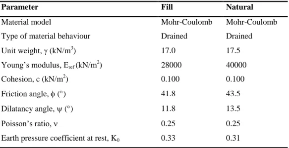
pressures and the generation of initial effective stress field. In this study, it supposed there is no ground water and the element fill is free draining. Material properties of the foundation soil and granular backfill soil, which are used in Mohr-Coulomb model, are shown in the table 3.1. Table 3.2 shows the values of plate properties used in analysis. Whereas, Table 3.3 shows the values of geogrid properties used in analysis. For modeling the foundation and backfill soil, the Mohr-Coulomb model was chosen with elastic-plastic soil model. The parameters of Mohr-Coulomb model were Poisson’s ratio , Yong’s modulus E, cohesion intercept c, friction angle and dilatancy angle .
Table 3.1. Material properties of the foundation soil and granular backfill soil.
Parameter Fill Natural
Material model Mohr-Coulomb Mohr-Coulomb
Type of material behaviour Drained Drained
Unit weight, (kN/m3) 17.0 17.5
Young’s modulus, Eref (kN/m 2 ) 28000 40000 Cohesion, c (kN/m2) 0.100 0.100 Friction angle, () 41.8 43.5 Dilatancy angle, () 11.8 13.5 Poisson’s ratio, 0.25 0.25
Earth pressure coefficient at rest, K0 0.33 0.31
Table 3.2. Values of plate properties used in analysis. Parameters Value Material type EI (kNm2/m) EA (kN/m) d (m) Elastic 60750 8100000 0.30
Table 3.3. Values of geogrid properties used in analysis. Parameters Value
Material type Elastic
CHAPTER THREE METHODOLOGY
30
3.5 PLAXIS PROGRAM
In 1986 PLAXIS advance as a connection program between Delft University and the Dutch Ministry of public works. It was used to solve geotechnical problems. In 1993, the PLAXIS Company took the all responsibility from Delft University, after that, many improvements were added to software in order to cover more areas of geotechnical engineering. PLAXIS version 8 is a finite element two directional, it can be used to conducted deformation analyses for many structures. Plane strain modeling can be used; in addition, it can used to solve the problems of slope stability and use -c reduction for calculation of factor of safety. The program can built-in soil model with using tools to represents sequences of geometry and real activates, geometry fill and excavation changes, loading condition changes and fill replacement (change in soil properties). It can input the geometry graphically and using tools for define the soil layers, stage of construction, boundary conditions and loads inputs of layers of soil [3].
PLAXIS can be depended to two-dimensional analyses for the stability and deformations. With PLAXIS, soil structures can be defined easily and meshed it automatically. Constriction aspect tools allow simulating constriction process and excavation by activating related soil regions, calculations enable to realistic simulation for non-linear, time depending, soil anisotropic behaviors that deals with pore pressure hydrostatic in soil. There is many output tools to check the underground soil construction. PLAXIS have to more applications, which are embankments consolidation analysis, rods displacements during and after construction, soil displacement around excavations, and more. This program is a realistic and relaxes for simulation constructions and full output details, which makes it the perfect solution for geotechnical design and analysis [21].
31
CHAPTER FOUR RESULTS AND DISCUSSION
4.1 Introduction
This study was carried out to investigate the behaviour of reinforced soil retaining walls, by using finite element analysis. Plaxis 8.2, a computer program used to conducts the analyses. The main geometry used in analyses is shown in figure 4.1.
In this study effect of reinforcement length, vertical spacing between reinforcements, wall thickness, wall embedment, and surcharge load, groundwater and reinforcement stiffness are investigated. In this study all models are in height of 10m and reinforcement length (L) was selected as 1H, 1.5H, 2H, 2.5H and 3H and vertical spacing between reinforcements (h) was selected as 0.5m, 0.75m and 1m. Factor of safety and permanent displacements of the models are calculated by using Plaxis.
CHAPTER FOUR RESULTS AND DISCUSSION
32 4.2 Unreinforced Soil Wall Analysis
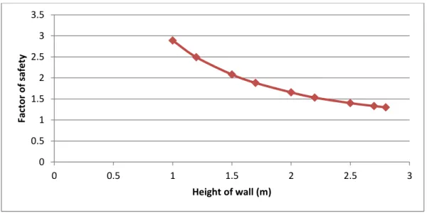
In order to know the optimum height of which the wall can be reached without adding reinforcement to soil, the model analyzed without reinforcement for a variable heights. After analyzed made it found that the height of 2.9 m is the maximum height for unreinforced case at which the soil body will be collapsed. From figure 4.2, it can be seen the decreasing in factor of safety values with increasing of wall height. Also from figure 4.3 it can be seen that the displacement increased with increasing the height of wall, these for case of no surcharge load.
Figure 4.2. Factor of safety against height of wall for unreinforced case.
Figure 4.3. Displacement against height of wall for unreinforced case.
0 0.5 1 1.5 2 2.5 3 3.5 0 0.5 1 1.5 2 2.5 3 Fact o r o f saf e ty Height of wall (m) 0 2 4 6 8 10 12 14 16 18 20 0 0.5 1 1.5 2 2.5 3 D isp lac e m e n t (m m ) Height of wall (m)
33
4.3 Effect of Length of Reinforcement and Vertical Spacing
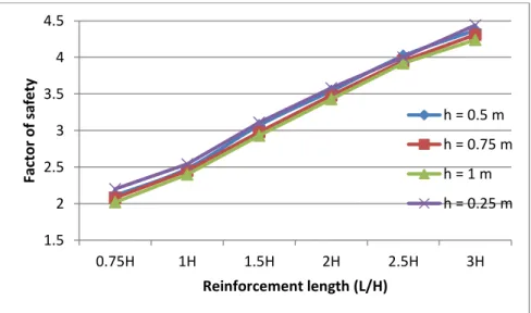
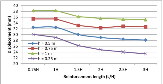
In this section of study, effect of length of reinforcement and vertical spacing between reinforcement layers, on the behavior of geosynthetic reinforced soil retaining wall explored. Reinforced vertical spacing was selected as 0.5m, 0.75m and 1m, whenever the reinforcement length was selected as 1H, 1.5H, 2H, 2.5H, and 3H. Factor of safety against reinforcement length and vertical spacing was plotted, for each case, as shown in figure 4.4a. In addition, geosynthetic reinforced soil retaining wall displacement against reinforcement length and reinforcement vertical spacing was plotted, for each case, as shown in figure 4.5.
From figure 4.4a, it can be noted that the reinforcement length has considerable effect on the factor of safety, as the general trend shows that the factor of safety is increasing linearly with increasing the reinforcement length. An increase in geogrid length will increase the factor of safety (FOS), whereas, an increase in vertical geogrid spacing will decrease the FOS values. Moreover, from figure 4.5 increase in geogrid length will decrease the total displacement of the geosynthetic reinforced soil wall, while an increase in vertical spacing of geogrid will increase the total displacement of reinforced soil wall. From figure 4.4a and figure 4.4b, it can be seen that the deference between the curves is very little with this range of length. i.e., decreasing in vertical spacing of geogrids has no effective influence on the factor of safety, therefor value of h=1m can be adopted for economic considerations.
Figure 4.4a. Effect of reinforcement length and geogrid spacing on the factor of safety.
1.5 2 2.5 3 3.5 4 4.5 0.75H 1H 1.5H 2H 2.5H 3H Fact o r o f saf e ty Reinforcement length (L/H) h = 0.5 m h = 0.75 m h = 1 m h = 0.25 m
CHAPTER FOUR RESULTS AND DISCUSSION
34
Figure 4.4b. Effect of reinforcement length and geogrid spacing on the factor of safety.
Figure 4.5. Effect of geogrid length and vertical spacing on the wall displacement.
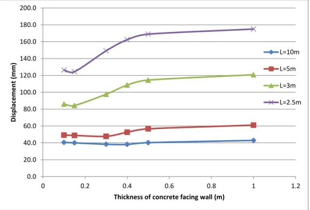
4.4 Effect of Thickness of Concrete Facing Wall
Effect of thickness of concrete facing wall were investigated by using variable values for thickness of concrete wall (t), which are t=0.3m, t=0.4m and t=0.5m. Relationship between thickness and factor of safety has plotted as shown in figure 4.6, which is showing that no considerable affect for the thickness on the factor of safety. Likewise relationship between thickness and displacement as shown in figure 4.7, which is also show that no considerable affect for the thickness on the displacement, wherefore, it gives an explanation of the efficient of reinforcement to reduce the thickness of facing wall.
1.9 2 2.1 2.2 2.3 2.4 2.5 2.6 0.75H 1H Fact o r o f saf e ty Reinforcement length (L/H) h = 0.25 m h = 0.5 m h = 0.75 m h = 1 m 20 22 24 26 28 30 32 34 36 38 40 0.75H 1H 1.5H 2H 2.5H 3H D isp lac e m e n t (m m ) Reinforcement length (L/H) h = 0.5 m h = 0.75 m h = 1 m h = 0.25 m
35
Figure 4.6. Effect of thickness of concrete facing wall on factor of safety.
Figure 4.7. Effect of thickness of concrete facing wall on displacement.
0 0.5 1 1.5 2 2.5 3 0 0.2 0.4 0.6 0.8 1 1.2 Fact o r o f saf e ty
Thickness of concrete facing wall (m)
L=10m L=5m L=3m L=2.5m 0.0 20.0 40.0 60.0 80.0 100.0 120.0 140.0 160.0 180.0 200.0 0 0.2 0.4 0.6 0.8 1 1.2 Di sp lac e m e n t (m m )
Thickness of concrete facing wall (m)
L=10m L=5m L=3m L=2.5m
CHAPTER FOUR RESULTS AND DISCUSSION
36 4.5 Effect Of Embedment Of Wall
In order to investigate the influence of embedment of wall (d) on soil behavior, variable values of embedment has took to plot its relationship against factor of safety and displacement. Results are shown in figure 4.8 and figure 4.9. From these two figures it can be seen that when the embedment depth of the wall increases, the factor of safety increase and the total displacements decrease especially for d=0.3H and d=0.35H. Herein, it can be notes the significant effect of reinforcement to fixing soil and to keep factor of safety within acceptable engineering limits especially for range d=0.1H to d=0.25H.
Figure 4.8. Effect of embedment of the wall on factor of safety.
Figure 4.9. Effect of embedment of the wall on displacement.
2.38 2.4 2.42 2.44 2.46 2.48 2.5 2.52 2.54 0.10H 0.15H 0.20H 0.25H 0.30H 0.35H Fact o r o f saf e ty
Embedment of the wall (d/H)
35.5 36.0 36.5 37.0 37.5 38.0 38.5 0.10H 0.15H 0.20H 0.25H 0.30H 0.35H D isp lac e m e n t (m m )
![Figure 1.1. Distribution of vertical foundation pressure for different height above the first reinforcement layer during construction [29].](https://thumb-eu.123doks.com/thumbv2/9libnet/3315408.10300/20.892.213.793.142.496/figure-distribution-vertical-foundation-pressure-different-reinforcement-construction.webp)
![Figure 1.4. Effects of reinforcement spacing on lateral deformation of reinforced soil zone [16]](https://thumb-eu.123doks.com/thumbv2/9libnet/3315408.10300/23.892.109.702.563.1099/figure-effects-reinforcement-spacing-lateral-deformation-reinforced-soil.webp)
![Figure 2.5. Failure of MSE wall due to lack of drainage and poor compaction of the reinforced fill soil [27]](https://thumb-eu.123doks.com/thumbv2/9libnet/3315408.10300/32.892.197.781.595.1029/figure-failure-mse-wall-lack-drainage-compaction-reinforced.webp)
![Table 2.2. Recommended minimum factors of safety with respect to failure modes [25].](https://thumb-eu.123doks.com/thumbv2/9libnet/3315408.10300/35.892.99.733.133.1059/table-recommended-minimum-factors-safety-respect-failure-modes.webp)
![Figure 3.5. The 15-node element as used in PLAXIS with degrees of freedoms and nodal forces [26]](https://thumb-eu.123doks.com/thumbv2/9libnet/3315408.10300/42.892.190.798.906.1062/figure-node-element-plaxis-degrees-freedoms-nodal-forces.webp)