ROBOTIC FABRICATION WORKFLOW FOR GYROID-LIKE
MODULAR SYSTEMS
MERYEM NUREFŞAN YABANİGÜL 116803016
INSTITUTE OF GRADUATE PROGRAMS
HISTORY, THEORY ANS CRITICISM IN ARCHITECTURE MASTER PROGRAM
Istanbul Bilgi University 2020
iii
ACKNOWLEDGEMENTS
I would like to extend my sincere thanks to Assoc. Professor Dr. A. Tuğrul YAZAR, who has made a great contribution to this research by guided and supported me with his knowledge, time, and understanding.
I am also grateful to Istanbul Bilgi University for supporting this research as a part of Scientific Research Project.
Special thanks to Rahman ÇELEBİ, for providing me the most efficient use of the Istanbul Bilgi University Faculty of Architecture Fabrication Laboratory during the research.
I must express my very profound gratitude to my parents Nilgün YABANİGÜL and Mesut YABANİGÜL for providing me with unfailing support, love and continuous encouragement throughout whatever I pursue, and my family for being there whenever I need.
iv
ABSTRACT
ROBOTIC FABRICATION WORKFLOW FOR GYROID-LIKE
MODULAR SYSTEMS
With the involvement of the industrial robots, a new field has been opened in architectural design and fabrication research. In this new field, architectural fabrication methods, material, and tool knowledge developed by researches. The thesis aims to generate a design and fabrication workflow by using robotic fabrication technologies and parametric design. Through this aim, this thesis presents a prototype design and production of a volumetric, porous, and modular system.
The hot wire cutter used in robotic architecture researches produces by melting foamed polymer materials with a heated insulating wire. The tool, which enables faster production compared to other devices, has some limitations in the production of free geometries. With the prototype fabrication to be conducted within the scope of the thesis, it also focused on the boundaries of the tool by producing a non-linear hot wire cutter.
Mathematical objects and robot used as catalysts for generating the workflow. In the thesis, the workflow and product variety of these two catalysts shown during the computational design-research process.
Key Words: Computational Design, Robotic Fabrication, Hot-wire Cutting, Minimal Surface,
v
ÖZET
GYROİD BENZERİ MODÜLER SİSTEMLERİN ROBOTİK
FABRİKASYON İŞ AKIŞI
Endüstriyel robotların dahil olması ile mimari tasarım ve üretim araştırmalarında yeni bir alan açılmıştır. Oluşan bu yeni alanda, mimarlık üretim yöntemleri, malzeme ve araç araştırmaları yapılarak bu konulardaki bilgi birikimi geliştirilmektedir. Tezin amacı robot teknolojileri ve parametrik tasarım kullanılarak tasarım ve üretim iş akışı oluşturmaktır. Tezde, bu hedef doğrultusunda hacimli, gözenekli ve modüler sistem prototipi tasarımı ve üretimi sunulmaktadır.
Robotik mimarlık araştırmalarında kullanılan sıcak tel kesici, ısıtılan bir yalıtkan tel ile, köpük haline getirilmiş polimer malzemelerin eritilerek üretim yapar. Diğer araçlara kıyasla daha hızlı üretim yapılmasına olanak sağlayan aracın, serbest geometrilerin üretiminde bazı kısıtlamaları mevcuttur.Tezde yapılacak üretimde bu kısıtlamalara da odaklanılmakta, robotik düz olmayan sıcak tel kesici ile üretim yapılmaktadır.
Üretilmesi hedeflenen iş akışı için matematiksel objeler ve robot katolizör olarak kullanılmıştır. Tezde, hesaplamalı tasarım-araştırma sürecinde bu iki katalizörün iş akışını ve ürün çeşitliliğini gösterilmektedir.
Anahtar Kelimeler: Hesaplamalı Tasarım, Robotik Fabrikasyon, Sıcak Tel Kesici, Minimal
vi
TABLE OF CONTENT
ACKNOWLEDGEMENTS ... ii ABSTRACT ... iv ÖZET ... v TABLE OF CONTENT ... viLIST OF FIGURES ... viii
LIST OF TABLES ... xiv
LIST OF SYMBOLS ... xv
1. INTRODUCTION ... 1
1.1. Aim of the Study ... 1
1.2. Scope of the Study ... 1
1.3. Research Questions ... 3
1.4. Literature Review ... 3
2. METHODOLOGY ... 8
2.1. The Triply-Periodic Minimal Surfaces ... 8
2.2. Digital Fabrication Strategies and Material Computation ... 14
2.3. Parametric Design and Coding Environments for Robotic Fabrication... 19
2.4. Methods of Analysis and Evaluation ... 20
3. CASE STUDY ... 21
3.1. Digital Modeling ... 21
3.2. The Geometric Structure of Gyroid ... 29
vii
3.4. Initial Tests of Robotic Hot-wire Cutting ... 36
3.5. Robot Setup and Tools ... 40
4. ROBOTIC FABRICATION EXPERIMENTS ... 46
4.1. The General Strategy of the Experiments ... 46
4.2. Experiment #1: Point-to-Point Motion Path ... 48
4.3. Experiment #2: Linear Motion Path ... 52
4.4. Experiment #3: Motion Path Based on the Fundamental Curve ... 55
4.5. Experiment #4: Motion Path Based on the Fundamental Surface ... 59
4.6. Experiment #5: Final Motion Path ... 67
4.7. Experiment #5 Mirror ... 72
4.7. Final Fabrication and the Outcomes ... 73
5. EVALUATIONS ... 76
5.1. The complexity of Parametric Models ... 76
5.2. Mathematical Precision and Accuracy ... 86
5.3. Generative Design Potentials ... 99
6. CONCLUSIONS ... 103
REFERENCES ... 107
URL REFERENCES ... 111
APPENDIX-A: Deformation Research of Minimal Surfaces ... 114
APPENDIX-B: Fundamental Patch Connection Lists... 117
APPENDIX-C: Unit Combinations ... 120
APPENDIX-D: Variations by Changing Wire Geometry ... 130
APPENDIX-E : The Final Generation and Simulation Code ... 136
viii
LIST OF FIGURES
Figure 1.2. The interdisciplinary research system of the thesis ... 2
Figure 1.3. Articulated teleoperation arm (URL-20,21) ... 4
Figure 1.4. Industrial articulated robot; Unimate, (URL-22) ... 4
Figure 1.5. Smart Dynamic Casting, ETH Zürich, 2012-2015 (URL-23) ... 5
Figure 1.6. ICD-ITKE Research Pavilion, University of Stuttgart, 2016-17 (URL-24) ... 6
Figure 2.1. (a) Philips Pavilion designed by Le Corbusier and Iannis Xenakis. (b) Soap film form-finding experiment by Frie Otto. (c) German Pavilion, Expo in 1967 designed by Frei Otto (URL-1, URL-2, URL3) ... 9
Figure 2.2. Basento Viaduct Bridge designed by Sergio Musmeci (URL-4, URL-5) ... 9
Figure 2.3. (a) A sculpture by Norman Carlberg in Northern Parkway Junior High School in 1971. (b) Scherk-Tower by Carlo H. Sequin in 2007. (c) Minimal Surfaces as Architectural Prototypes by Vlan Tanu in 2009 (URL-6, URL-7, URL-8)... 10
Figure 2.4.Sculpture installations designed by Erwin Hauer (URL-9, URL-10) ... 10
Figure 2.5. Commune-Action Walls research design and production (URL-30) ... 11
Figure 2.6. (a)(b) The exterior of the Taichung Metropolitan Opera House. (c) Interior of the Taichung Metropolitan Opera House (d) Section drawing of the Taichung Metropolitan Opera House (URL-11, URL-12) ... 12
Figure 2.7. (a)(b) The roof garden of the Taichung Metropolitan Opera House. (c)(d) Terraces of the Taichung Metropolitan Opera House (URL-13) ... 12
Figure 2.8. Double Negative project designed by Khoa Vu (URL-14) ... 13
Figure 2.9. The Meditation Club project designed by Khoa Vu (URL-15) ... 13
Figure 2.11. Periscope Foam Tower designed by Matter Design Studio (URL-17) ... 17
Figure 2.12. Case-Specific Robotic Fabrication of Foam Shell Structures researched by Marko Jovanovic, Marko Vucic, Dejan Mitov, Bojan Tepavčević, Vesna Stojakovic and Ivana Bajsanski (URL-18) ... 18
Figure 2.13. Gyroid and Saddle tower fabrication with hot-wire cutting method (URL-31) ... 19
ix
Figure 3.1. Variation of Gyroid minimal surface by changing the equation ... 23
Figure 3.3. Minimal surface generation code by equation ... 24
Figure 3.4. The outcome of the ex.1; generating minimal surface cubic unit cells in Grasshopper; (a) Top view (b) Front view (c) Perspective view ... 26
Figure 3.5. The outcome of the ex.2; generating minimal surface fundamental patches in Grasshopper; (a) Top view (b) Front view (c) Perspective view ... 27
Figure 3.6. (a) The direction of rotation of the KUKA KR20 industrial robotic arm (b) Work envelope, side view. (c) Work envelop, top view. Dimensions are in mm (URL-28) ... 28
Figure 3.7. (a) The cubic unit cell of the Gyroid surface. (b) The fundamental unit. (c) The fundamental patch (d) The fundamental region ... 29
Figure 3.8. Rotations of the fundamental units in the Gyroid cubic unit cell. (a) The reference fundamental surface for rotating; G. (b) G1 (c) G2 (d) G3 ... 30
Figure 3.9. Evolution of the Gyroid cubic unit cell ... 30
Figure 3.10. Splitting a cube with the cubic unit cell surface of the Gyroid and generating a wall ... 31
Figure 3.11. Motion path generation of the Gyroid surface fabrication with straight wire ... 32
Figure 3.12. Edge curves of the Gyroid fundamental patch ... 33
Figure 3.13. Wire form ... 33
Figure 3.14. The active section of the wire moves from point 1 to point 2 ... 33
Figure 3.15. EPS holding tool dimensions in mm ... 34
Figure 3.16. EPS holding tool attached to the robot ... 35
Figure 3.17. EPS unit blocks ... 36
Figure 3.18. Experiment tool for wire and power supply ... 37
Figure 3.19. Wire and EPS density experiment ... 38
Figure 3.20. Experiment tool for speed and heat ... 39
Figure 3.21. First experiment and result ... 39
Figure 3.22. The first try of the Nitinol wire training ... 41
Figure 3.23. The second try of the Nitinol wire training ... 42
Figure 3.24. Nitinol wire mold pieces ... 42
x
Figure 3.27. Hotwire cutter tool frame and power supply ... 44
Figure 3.28. TCP position information for tool calibration ... 44
Figure 3.29. The base recreated in Rhino with the coordinate information ... 45
Figure 3.30. Gyroid fundamental patch edge geometries ... 46
Figure 4.1. Generation of the wire representation ... 47
Figure 4.2. Generation of the references ... 47
Figure 4.3. Plane positions on the references ... 48
Figure 4.4. Generation of the experiment#1 motion path ... 49
Figure 4.5. TCP position of the experiment#1. Dimensions are in mm ... 49
Figure 4.7. Cutting photos of the experiment#1 ... 50
Figure 4.6. Grasshopper definition of the experiment#1 ... 50
Figure 4.8. Cut geometry of the experiment#1 ... 51
Figure 4.9. Point-to-point movement path of the experiment#1 ... 51
Figure 4.10. Point-to-point movement path of the experiment#1... 52
Figure 4.11. Generation of the experiment#2 motion path ... 52
Figure 4.12. Grasshopper definition of the experiment#2 ... 53
Figure 4.13. TCP position of the experiment#2. Dimensions are in mm ... 53
Figure 4.14. The movement path of the experiment#2 ... 54
Figure 4.15. Cutting photos of the experiment#2 ... 54
Figure 4.17. Grasshopper definition of the experiment#3 ... 56
Figure 4.19. Side view of the TCP movement during the cut ... 57
Figure 4.20. Generation of the experiment#3 motion path ... 58
Figure 4.21. Cutting photos of the experiment#3 ... 58
Figure 4.22. Cut geometry of the experiment#3 ... 59
Figure 4.23. Gyroid fundamental patch generation code ... 60
Figure 4.24. Generation of the experiment#4 motion path ... 61
Figure 4.25. Contour and plane generation of the experiment#4 for the motion path ... 62
Figure 4.26. Grasshopper definition of the experiment#4 ... 62
Figure 4.28. Cutting photos of the experiment#3 ... 63
xi
Figure 4.30. Experiment#4 motion of the EPS block and Gyroid fundamental curve front view
... 66
Figure 4.31. Grasshopper definition of the experiment#5 ... 67
Figure 4.32. Grasshopper definition of the experiment#5 cutting wire representation ... 68
Figure 4.34. Generation of the experiment#5 motion path ... 70
Figure 4.35. Experiment#5 motion of the EPS block and Gyroid fundamental curve wire front view ... 71
Figure 4.36. Cutting photos of the experiment#5 ... 71
Figure 4.37. Definition of the experiment#5 mirror ... 72
Figure 4.39. Cutting photos of the experiment#5 mirror ... 72
Figure 4.40. Gyroid fundamental patches cut from EPS blocks ... 73
Figure 4.41. Connection combination list of A fundamental patch ... 74
Figure 4.45. A18, A19, A20, B’23, B’24, B’25 ... 75
Figure 4.46. A’5, B3, B2 ... 76
Figure 5.1. Grasshopper definition of the experiment#1 ... 77
Figure 5.2. Grasshopper definition of the experiment#2 ... 78
Figure 5.3. Grasshopper definition of the experiment#3 ... 79
Figure 5.4. Grasshopper definition of the experiment#4 ... 80
Figure 5.5. Grasshopper definition of the experiment#5 ... 81
Figure 5.6. Grasshopper definition of experiment #5 mirror ... 83
Figure 5.7. Plane difference between experiment#5 and #5 mirror Grasshopper definition. Left; Movement control planes of experiment #5; Right; Movement control planes of experiment #5 mirror ... 83
Figure 5.8. Robot motion target difference between experiment#5 and #5 mirror Grasshopper definition. Left; Robot motion targets of experiment#5; Right; Robot motion targets of experiment#5 mirror ... 84
Figure 5.9. TCP position difference between experiment#5 and #5 mirror Grasshopper definition. Left; TCP position of experiment#5; Right; TCP position of experiment#5 mirror 84 Figure 5.10. TCP positions cooperation ... 85
xii
Figure 5.12. Grasshopper definition of the simulation in experiment #4 ... 87
Figure 5.13. Experiment #4 simulation output ... 88
Figure 5.14. Grasshopper definition of the simulation in experiment #5 ... 89
Figure 5.15. Experiment#5 simulation output (a) Movement path (b) Rotated planes on the movement path (c)Block placed to the planes (d) Sections of the blocks (e)Surfaces of the sections (f) Surface of the wire and projection (g) Intersections of the (e) and (f) (h) Final production simulation ... 90
Figure 5.16. Simulation steps of the experiment#5 mirror with the simulation code ... 91
Figure 5.17. The simulation code ... 92
Figure 5.18. Comparing the result of the bounding boxes dimensions of the outputs of the simulations ... 93
Figure 5.19. Surface simulation group of the final simulation code ... 93
Figure 5.20. The result of the bounding box dimensions of the output of the final simulation 94 Figure 5.21. Comparison of simulation, physical and 3D scan outputs of the experiment#5 . 95 Figure 5.22. Error rate analysis code of the 3D scan and digital equation outputs of the experiment#5 ... 95
Figure 5.23. From left to right: 3D scan model; Equation output; Mesh endpoints of the 3D scan model; Closest points of the equation mesh and point cloud of the 3D scan model ... 96
Figure 5.24. Comparison of the physical and digital products ... 98
Figure 5.20. Simulation groups in final code ... 99
Figure 5.21. The final generation and simulation code ... 100
Figure 5.22. Gyroid production wire and final model ... 101
Figure 5.23. Wire geometry code and variation equations ... 102
Figure 5.24. Variation #1; Product simulation of manually drawn wire curve ... 102
Figure 6.1. Research workflow diagram ... 104
Figure A.1 Variation of Holes minimal surface by changing the equation ... 114
Figure A.2. Variation of Scherk minimal surface by changing the equation ... 115
Figure A.3. Variation of Daimand minimal surface by changing the equation ... 116
Figure B.1. Connection combination list of A’ fundamental patch ... 117
xiii
Figure B.3. Connection combination list of B’ fundamental patch ... 119
Figure C.1. A17, A16, B’11, B’12 ... 120
Figure C.2. A’3, B4, B17 ... 121
Figure C.3. A3, A10, B’10 ... 122
Figure C.4. A9, A16, B1, B8 ... 123
Figure C.5. A7, A2, B5, B13 ... 124
Figure C.6. Variation of A7, A2, B5, B13 patches ... 125
Figure C.7. A4, A8, A15, B’2, B’3, B’4, B’8 ... 126
Figure C.8. B’6, B’4, B’12 ... 127
Figure C.9. A’2, B’5 ... 128
Figure C.10. A9, A15, B’1, B’11 ... 129
Figure D.1. Variation #3 ... 130 Figure D.2. Variation #4 ... 131 Figure D.3. Variation #5 ... 132 Figure D.4. Variation #6 ... 133 Figure D.5. Variation #7 ... 134 Figure D.6. Variation #8 ... 135
Figure E.1. Final code ... 136
xiv
LIST OF TABLES
Table 1.1. Table of the robotic fabrication research projects in architectural schools. Research projects are not limited by the table ... 7 Table 5.1. The difference in the Grasshopper codes between the six experiments. The
significant difference is the motion time of experiments 5 and 5 mirror and others. The reason behind that difference is in experiment#5 and #5 mirror, robot arm does not go back to the home position after the cut is done. ... 85
xv
LIST OF SYMBOLS
% Percent 3D 3 Dimension A Ampere Assist. Assistant Assoc. AssociateCAD Computer Aided Design
CAM Computer Aided Manufacturing
cm Centimeter
cm3 Square Centimeter
CNC Computer Numerical Control
Dr. Doctor
EPS Expanded Polystyrene
ft Feet
kg Kilogram
kg/m3 Kilogram / Cubic Meter
KRL KUKA Robotic Language
m2 Square Meter
mm Millimeter
NiCr Nickel-Chromium
xvi TPMS Triply Periodic Minimal Surface
1
1. INTRODUCTION
1.1. Aim of the Study
The study aims to create a prototype of a volumetric, porous, and modular system. This thesis proposes a design and production workflow for the above aim by utilizing robot technology and parametric modeling.
With the involvement of the industrial robots in architecture discipline, a new field has been opened. In this new area, architectural fabrication methods, material and tool knowledge developed by architecture schools and independent design researchers. It aimed to explore the production methods of the future by expanding the boundaries of robotic production with the researches conducted by researchers from various disciplines.
The hot wire cutter used in robotic architecture researches produces by melting foamed polymer materials with a heated insulating wire. The tool, which enables faster production compared to other tools, has some limitations in the production of free geometries. In the prototype production to be made within the scope of the thesis, it also focused on the limitations of the tool by producing with a non-flat hot wire cutter.
1.2. Scope of the Study
The potentials of the robot arm can be revealed through researches carried out by different disciplines. This study incorporates a multi-disciplinary process by the researcher. It involves the computational design, computer programming, and robotic fabrication.
2
Figure 1.2. The interdisciplinary research system of the thesis
The scope of Computational Design:
Within the scope of the computational design of the research, the focus is on modular masonry structure systems designed in the computer environment.
The scope on Computer Programming:
The robot can programmed in several options. Computer-based robot programming is one of the most common methods among architects. Architects have developed plug-ins like Robots to control the robot.
Another topic to be explored in the computer environment is mathematical objects. New computer software generates and analyses math objects and presents them to designers.
Therefore, on the scope of computer programming, focused topics are dataflow programming in Grasshopper and math objects.
3 The scope of Robotic Fabrication:
This research contains an industrial robotic arm with an unusual usage. In hotwire robotic production for research purposes, the general use of the wire is straight. In this thesis, robotic hotwire fabrication to be held with a non-linear hotwire cutter system.
1.3. Research Questions
Question 1: Is it possible to design and produce an approximation of a double-curved math object with a robot hotwire cutting technique?
Question 2: What kind of an integrated design and production workflow, along with necessary skills and knowledge sets, are required to answer the first question?
Question 3: What are the performances and potentials of this workflow in terms of the key scope of the research?
1.4. Literature Review
The word “Robot” which comes from “Robota” was first used by a Czech writer named Karel Capek in “Rossum’s Universal Robots” theatrical play in the 1920s. Capek used this word, which means heavy work in the Czech language, for slave machines that Rossum and his son created to serve people (Niku, 2001; Ichbiah, 2005).
In 1927, in the Metropolis film directed by Fritz Lang, Maria appeared as a human-form robot. This term and the concept that it accompanies became widespread by using art in various fields such as literature, cinema, and theater. The word “Robotics” was first used by science fiction writer Isaac Asimov in 1942 in the novel Runaround (Gasparetto & Scalera, 2019).
The Robot term defined as “a robot is a reprogrammable multifunctional manipulator designed to move materials, parts, tools or specialized devices through variable programmed
4
motions for the performance of a variety of tasks” by the Robot Institute of America (Wallén, 2008).
An example of the articulated human-controlled arm is the teleoperator, designed by Raymond Goertz in the 1940s and 1950s. Articulated arms used for nuclear research in Courtesy Argonne National Labs in the USA. The arms control systems were electrical and controlled behind shields. (Niemeyer, et al. 2008)
Figure 1.3. Articulated teleoperation arm (URL-20,21)
The programmable industrial articulated robot arms first produced in 1961. In 1956 George Devol and Joseph Engelberger founded a company. As a result of the studies carried out, the first industrial robot arm Unimate developed in 1961. Later on, Unimate was integrated into a conveyor at the General Motors factory and used for a single task. With the development of industrial robot technology, it has significantly affected the speed of mass production (Gasparetto & Scalera, 2019; Ichbiah, 2005).
Figure 1.4. Industrial articulated robot; Unimate, (URL-22)
Although robotic studies thought to be limited to mass production and engineering fields, recent research has spread to many disciplines, including architecture, cinema, and health. With robots, the ability to produce far beyond the existing boundaries in architectural production has
5
accelerated research on issues such as materials and architectural production (Braumann & Brell-Cokcan, 2012).
Articulated robots, which are used extensively in the automotive industry, are used in a wide variety of tasks, such as welding or spray paint, since they are suitable for replacing or adding parts in the latest joint. In particular, articulated robotic arms have been involved in architectural research, as they can be used in a wide range of tasks and a wide range of domains compared to other production tools. Research is carried out not only in architectural design offices but also in architecture faculties in universities such as ETH Zurich, TU Vienna, Stuttgart, Architecture Association, and Michigan.
Leading examples of robotic fabrication research have been conducted since 2006 at the Gramazio & Kohler research center. Most of the research is about new materials and ways of use that can be used for building products, as well as the re-examination of traditional building materials, exploring the limits of the materials and robot, the most efficient use of the robot.
Smart Dynamic Casting, a research project between 2012-2015 with the collaboration of Gramazio & Kohler Research Center and ETH Zürich, produces complex concrete structures using robotic arms. The research is an attempt to test the limits of concrete production systems that exist today. The production of free-from designs is expensive due to the use of non-standard molds. Smart Dynamic Casting aims to eliminate the need for individually made molds for the construction of complex concrete structures (Fritschi, et al., 2017).
6
The Institute for Computational Design and Construction (ICD) at the University of Stuttgart is conducting advanced research on robotics production. ICD is an institute established to research the computational design and computer-aided manufacturing processes in architecture. Like Gramazio & Kohler, the structural systems and the use of traditional materials examined in ICD; however, researches in the performance of new materials investigated more intensively.
Figure 1.6. ICD-ITKE Research Pavilion, University of Stuttgart, 2016-17 (URL-24)
ICD / ITKE Research Pavilion, which built between 2016-2017, is a structural system produced by three different robots, two of which are robotic arm and one drone, with fiber composite materials. A large-scale and long-span structural system made of fiber composite material, which is lightweight and structural. The main subject of this research is the structural performance and material behavior of composite material that not used as building materials (Felbrich, et al., 2017).
Interdisciplinary environments for the new system and material researches are essential for transferring information from different disciplines. Comprehensive research is more difficult due to the high cost of materials and mechanisms and the need to work in an interdisciplinary environment. However, the architecture faculties of universities in various countries contribute to the robotics production literature by incorporating robotic arms. Providing education in this field, which is almost new for architecture, contributes to the development of construction and design practices. The students are informed about the design, engineering, and construction fields, and the way to improve the calculation processes in architecture opened. The combination of different disciplines ensures that their spatial, formal, and structural potentials emerge in the best possible way. Besides, parametric design, material performance, structure, such as
7
contributing to the development of each time on top of the issues, contributed to the development of these issues in each production to create a database with the information acquired.
Table 1.1. Table of the robotic fabrication research projects in architectural schools. Research projects are not limited by the table
8
2. METHODOLOGY
2.1. The Triply-Periodic Minimal Surfaces
A minimal surface is a zero-curvature surface that covers the minimum area within the boundaries of a pre-defined space (Sierra & Rodriguez, 2014; Rossi & Buratti, 2017; URL-24). Initial examples of minimal surfaces were introduced by German mathematician Hermann Schwarz in 1865. In 1883, Edvard Rudolf Neovius, who was Schwarz’s student, extended the research on the minimal surfaces (Tenu, 2009; Weber & Wolf, 2011). In 1970, Alan Schoen published research that contains 17 periodic minimal surfaces. He illustrated, and modeled five known minimal surfaces and introduced twelve new ones (Sierra & Rodriguez, 2014; Schoen, 1970).
Since their discovery, minimal surfaces continuously catch the attention of a broad range of disciplines, from art and architecture to chemistry and engineering. In architecture, minimal surfaces mostly utilized in structural systems such as bridges, shells, and roof systems. Philips Pavilion (Figure 2.1), designed by Le Corbusier and Iannis Xenakis, is a well-known example of the use of minimal surface as an architectural element. Basento Viaduct (Figure 2.2) is a concrete shell bridge, designed by the Italian engineer and architect Sergio Musmeci. Frei Otto is another essential figure on the design-research studies of architectural minimal surfaces. He used soap films as the form-finding tools for his lightweight structure designs (Figure 2.1) (Tenu, 2009).
9
Figure 2.1. (a) Philips Pavilion designed by Le Corbusier and Iannis Xenakis. (b) Soap film form-finding experiment by Frie Otto. (c) German Pavilion, Expo in 1967 designed by Frei Otto (URL-1, URL-2, URL3)
Figure 2.2. Basento Viaduct Bridge designed by Sergio Musmeci (URL-4, URL-5)
Triply periodic minimal surfaces (TPMS), also known as infinite periodic minimal surfaces, are a family of minimal surfaces, which have the quality of growing and extending in three directions. This is established by the symmetry transformations on fundamental units in cartesian space, without intersecting or interrupting each other. (Rossi & Buratti, 2017; Sierra & Rodriguez, 2014; Vamvakidis, 2007; URL-24) TPMS can be generated by rotation and mirror of a small piece, known as a “fundamental region”. Similar to the other minimal surfaces, TPMS attracts the attention of art and architecture because of its geometric sophistication. Artists such as Norman Carlberg, Vlan Tanu, and Carlo Sequin are studying and utilizing TPMS on their sculptures.
10
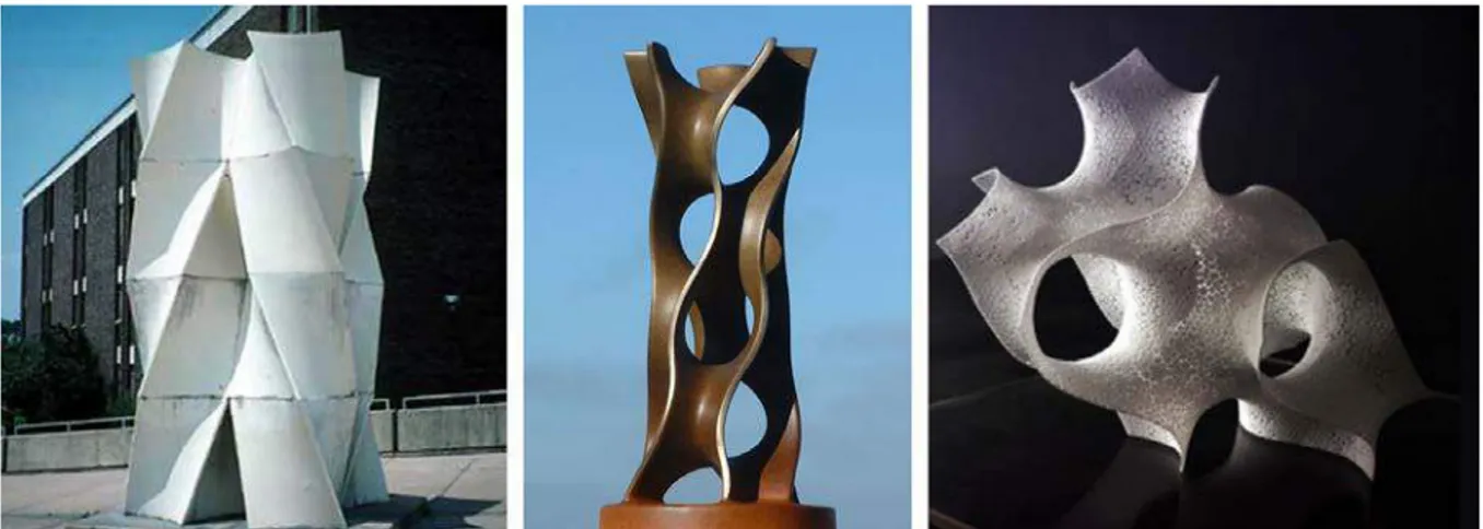
Figure 2.3. (a) A sculpture by Norman Carlberg in Northern Parkway Junior High School in 1971. (b) Scherk-Tower by Carlo H. Sequin in 2007. (c) Minimal Surfaces as Architectural Prototypes by Vlan Tanu in 2009
(URL-6, URL-7, URL-8)
Erwin Hauer is another influential artist who explored the geometric features of minimal surfaces. He is known as a “modular constructivist”, who structured modules with infinite patterns of repetition (URL-27). His art is about exploring the modularity of infinite continuous surfaces (Figure 2.4) (URL-25).
Figure 2.4.Sculpture installations designed by Erwin Hauer (URL-9, URL-10)
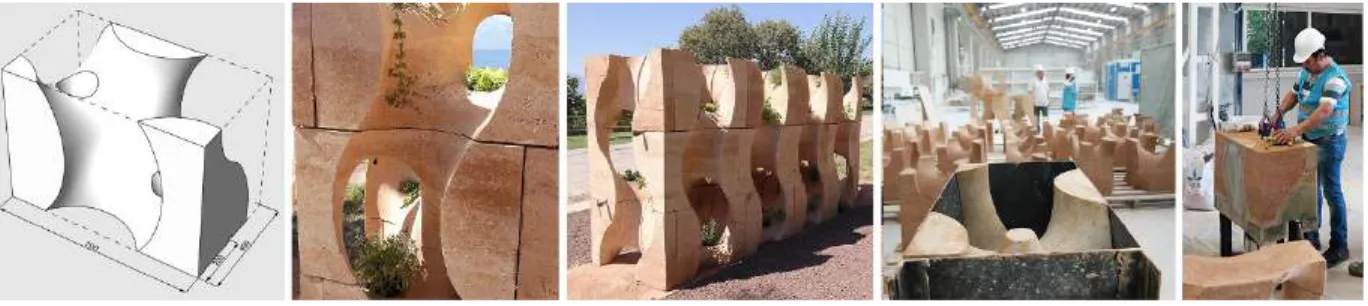
Another example in the intersection of art and architecture is the Commune-Action Walls installation designed by POTplus Design Research Group, founded by Funda Akiperk and Tuğrul Yazar within the Fourth International Antalya Architecture Biennial in 2017. Commune-Action Walls is the research of transforming TPMS to a building element by using traditional
11
building techniques. The structural system established with the permaculture system by planting edible plants to the slots on modules. Modules produced in a factory environment with the soil compaction method for precision with a mold in the form of the Gyroid fundamental unit. Gyroid geometry allowed producing the design form single module, which forms continuous surfaces by using 90-degrees rotated units (Figure 2.5) (Akipek, 2018).
Figure 2.5. Commune-Action Walls research design and production (URL-30)
TPMS are modular and repetitive, continuous, and variable, and their labyrinth-like surfaces can extend in all directions in space systematically (Sierra & Rodriguez, 2014; Tenu, 2009). These double-sided, continuous labyrinths create a unique spatial quality that mentioned in several architectural projects. In addition, the labyrinth system of TPMS opens new and original research fields in building physics with their potential performances in absorbing sound, acoustic, lighting, and temperature control. For this reason, it would be efficient to use these geometric systems in spaces that need sound diffusion, like theaters, auditoriums, or exhibition areas (Sierra & Rodriguez, 2014). Although there are potential benefits, TPMS not widely utilized in architectural design because of its specific formal characteristics. Taichung Metropolitan Opera House is the most relevant application of TPMS in architecture. Opera House, designed by Toyo Ito and Associates, is based on a deformation of P Schwarz's minimal surface (Sierra & Rodriguez, 2014), which consists of a rectangular prism with horizontal and vertical voids. The curved walls and voids generated by the approximation of the minimal surface and used for various functions such as circulation, theater, and atrium spaces. Because of the variability of the geometric system, the measurements of the spaces arranged as needed. Toyo Ito briefly explained the design process by saying, “The geometry came first, and then we forcibly introduced the theaters” (Ito, Grand Opera, 2016). The curved structural elements of
12
the building also function as the spatial separation elements. The geometrical system allows the optimal distribution of the loads (Aziz & El Sherif, 2016; Bognar, 2017).
Figure 2.6. (a)(b) The exterior of the Taichung Metropolitan Opera House. (c) Interior of the Taichung Metropolitan Opera House (d) Section drawing of the Taichung Metropolitan Opera House (URL-11, URL-12)
Minimal surfaces do not give priority to creating functional spaces in architecture. For this reason, it needed geometrical deformation and additional elements such as horizontal and/or vertical planes for spatial needs (Chen, 2016). Continuity can be sustained by deforming the minimal surface, but adding planar surfaces such as slabs, walls, and facade elements interrupt the spatial fluidity of the system. Due to this reason, the Taichung Metropolitan Opera House project is an important example of the intersection between mathematical and architectural domains in terms of the contrasts between the accuracy and geometric qualities of the TPMS, and the functional necessities of architecture. According to Bognar, this is the “...inherent paradox of the system” (Figure 2.6 and Figure 2.7).
Figure 2.7. (a)(b) The roof garden of the Taichung Metropolitan Opera House. (c)(d) Terraces of the Taichung Metropolitan Opera House (URL-13)
Other innovative architectural examples of minimal surfaces are Meditation Club and Double Negative projects, designed by Khoa Vu. In these two projects, geometric potentials of minimal
13
surfaces augmented by creating a fluid and continuous spaces that can modularly extend and vary by the scale and form of the modules (URL-14; URL-15). In Double Negative, the surfaces become the building by variation of the geometry as needed, without any interruption. This project presents a general spatial solution, suitable for functions like a gallery, museum, and library. It is conceptual and formal research aiming to uncover the potentials of using minimal surfaces with their unique spatial qualities (Figure 2.8) (URL-14).
Figure 2.8. Double Negative project designed by Khoa Vu (URL-14)
The Meditation Club project also presents a fluid and continuous public spaces. Within this fluidity, the designer focused on creating private spaces (URL-15). In this project, the concepts of structure, wall, ceiling, and stairs are conceptually “melted” and integrated, within the building itself (Figure 2.9).
14
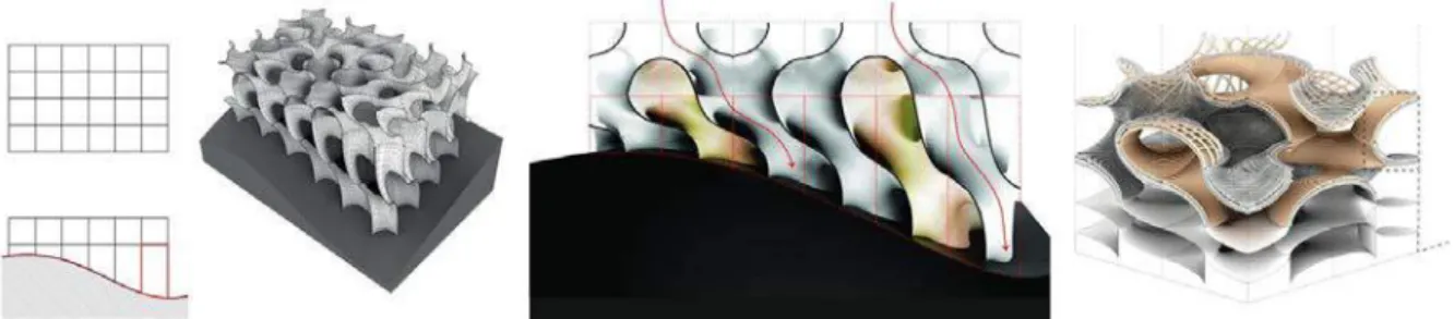
Another architectural research example designed in 2013 at The University of Hong Kong Master of Architecture studio named Groovy Tectonics, led by Tom Verebes with Paul Wintour. The main aim of the studio was researching curvature, mathematical concepts, tools for their spatial potentials. One of the final projects of the studio was named “Minimal Surfaces,” designed by Kwok Hoi Lam Helen and Wong Yok Fai Arnold (Figure 2.10). In this project, designers researched modularity, continuity, and variability potentials of the minimal surfaces for continuous spaces and transformation of modules according to topographical change (URL-16).
These examples indicate that architects are increasingly using and researching minimal surfaces for form and structure solutions of their designs. It is still an open and promising research field of utilizing the formal qualities and generative potentials of minimal surfaces in the search for solutions to the new and challenging problems of architecture in the future.
Figure 2.10. The Minimal Surfaces project designed by Kwok Hoi Lam Helen and Wong Yok Fai Arnold (URL-16)
2.2. Digital Fabrication Strategies and Material Computation
With the recent developments in Computer-aided Design (CAD) and Computer-aided Manufacturing (CAM) technologies, the cognitive layer between digital models and physical production disappears. Digital fabrication technologies enable designers to design and produce free-form geometries with mathematical accuracy and precision. There are various production approaches for free-form or double-curved architectural elements, including additive and subtractive manufacturing methods. In additive fabrication, like three-dimensional (3D) printing, the production material is cast layer-by-layer until the desired outcome achieved.
15
Subtractive fabrication based on removing the pre-defined volumes from solid materials or panels. Laser cutting and Computer Numerical Control (CNC) milling are the technologies based on subtraction. (Kaftan & Stravric, 2013; Rust, et al., 2016)
The generally accepted fabrication methods for free-form architectural geometry are 3D printing and CNC milling. However, depending on the geometric features of the design, the most economical and fastest fabrication approach usually involves subtraction. For example, hotwire of hot blade cutting of expanded Polystyrene foam (EPS) is one of such efficient techniques utilized in architectural design-researches extensively (Rust, et al., 2016). Hot-wire and hot blade cutters have different features. The most known use of a hotwire cutter tool includes a straight wire. It is one of the most practical tools for fabricating simple, non-double-curved geometries. The tool works by melting EPS foam, leaving a gap between the cut pieces, which is proportional to the heat of the wire. The wire should be durable enough to sustain the friction of the material while cutting. It should also be resistant to the deformation effects of the extreme heat. This is why, in general, thick and straight wires used in this technique. The straight wire limits the possible geometric outcomes of the process. Nevertheless, there are a few fabrication examples that used hotwire cutters for forming complex geometries by implementing a carving technique. Because of the possibility of giving shape to the cutting edge, hot blades or hot knives are generally more suitable for fabricating double-curved or complex geometries. In this research, a hotwire will be modified and used for cutting Gyroid-like geometries.
The main challenge to cut double-curved surfaces with non-linear hot-wire is to shaping the wire in the correct form and keeping the wire stable in the given form. In this research, the initial wire tests held with three different wires. In the initial cutting tests, thick nickel-chrome (NiCr) wires proved not useful in heating and cutting EPS. This is why thin shape-memory wires became an alternative solution. In this research, the initial wire tests held with three different wires. Two of them are nickel-chrome (NiCr) wires with 0.9 mm and 1.2 mm thicknesses. NiCr is the standard cutting wire used in industrial and hobby foam cutting practices. Because of the stability issues mentioned above, a shape memory wire with 1 mm thickness is also tested and proved to be useful.
16
The next step of the setup was to investigate tools that generally used in foam cutting applications. Hand-held hotwire or hot blade tools are usually small, light-weight, and compact tools that enable fast cutting results. There are two types of hand-operated tool systems, namely hand-held and table-top. To accurately cut any free-form geometry by using the hand-operated tools, the tool or the foam block should be fixed and referenced properly to avoid precision problems. It is also difficult to cut continuous and seamless surfaces by manual actuation. CNC hot-wire cutting, on the other hand, enables more complex geometries to be cut with precision. CNC can be regarded as a Cartesian robot; therefore, it can move in three orthogonal directions as X, Y, and a limited amount of Z, without orientation, angles A, B, or C. Some CNC systems include a turning table, which allows non-orthogonal motion paths. Industrial robots are more flexible than CNC. They can orientate any attached tool not only in six axes as X, Y, Z, but also rotation around those axes, as A, B, and C. Industrial robots can manipulate the material in any coordinate in space with the chosen tools attached to them (Ivanovskis, 2017). In this paper, the six-axis industrial robot manipulator KUKA KR-20 will be described with a more common short name, “robotic arm”.
Robotic arms are relatively fast, cheaper to work with, providing more working volume, and can perform more complex movements and various tasks than other digital fabrication systems (URL-28). With the robotic arms, designers can fabricate their designs by controlling the motion path and sequence, speed, approach, and other operational parameters. Two-dimensional subtractive fabrication systems like CNC milling and laser cutting also provide these parameters; however, their accessibility is limited.
Expanded Polystyrene (EPS) is recyclable, lightweight, low-cost, quick formable, and easy-to-assemble material (Jovanović, et al., 2017). Because of these features, EPS is a suitable material for design research and prototyping. Density is a distinctive feature of EPS foams. Particles of the low-density foam are bigger and easier to cut by heat. However, it has a lower resolution than foams that have more density. This is why, the precision of the outcome, especially the complex shapes such as double-curved surfaces is limited. High-density foam is heavier than low-density foam, yet, it has more resistance to pressure. There is a gap created, as the hotwire melts the material while cutting. This gap of the low-density foam is wider than higher density
17
foams that cut with the same wire and power. In addition to that, the fumes created by melting with the thermal cut is observed more with low-density foam. In this research, 20 kg/m3 and a less dense 60x60x60cm EPS foam blocks used for the experiments.
Thermal cutting tools are not only using in the construction industry. In recent years, they are also getting the attention of the design and fabrication related research fields. There are several robotic fabrication research examples aimed at exploring geometric performances, motion planning, or material performance of hotwire cutting systems.
Figure 2.11. Periscope Foam Tower designed by Matter Design Studio (URL-17)
Periscope Foam Tower, designed by Matter Design Studio, is one of the examples in design research with hotwire cutting. This project designed for a competition that required installation in less than 24 hours on a 10-ft-sq plot with a two-person team (Figure 2.11). Designers managed the requirements with the advantages of EPS as it is lightweight, easy to join, and easily formable with a hotwire cutter. The 50-ft long temporary installation fabricated by carving ruled
18
geometries from over 500 units of EPS blocks with a hotwire cutter that was attached to the seven-axis industrial robot. These blocks stacked into sub-assemblies, which are three-ft long. For stabilizing the sub-assemblies, plywood profiles placed at the bottom and top of each stack. The Tower was installed by adding fourteen sub-assemblies on top of each other and held down with the tension cables (FABLAB, 2017).
Figure 2.12. Case-Specific Robotic Fabrication of Foam Shell Structures researched by Marko Jovanovic, Marko Vucic, Dejan Mitov, Bojan Tepavčević, Vesna Stojakovic and Ivana Bajsanski (URL-18)
Another design research example based on constructing a vault-like thin shell structure with EPS, which was cut by a robotic controlled hotwire cutter. This project designed and manufactured for the European Research Night by Marko Jovanovic, Marko Vucic, Dejan Mitov, Bojan Tepavčević, Vesna Stojakovic, and Ivana Bajsanski. The overall form of the project was a distorted Igloo, designed with three entrances for visitors to move through. The shell was tessellated in hexagonal double-curved panels and fabricated from EPS blocks with a hotwire cutting tool in 40x40 cm size (Figure. 2.12). Two robotic arms collaboratively used in this research. A tool for holding the EPS foam was attached to one robot, while the other holds the hotwire cutter (Jovanović, et al., 2017).
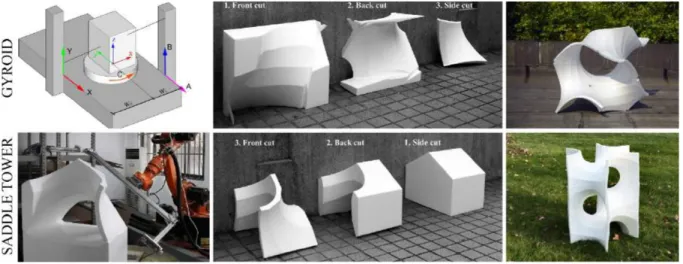
A research focuses on Gyroid production with hot-wire cutter. In this example, the research aims to deconstruct Gyroid, Saddle tower, and Costa's minimal surface to analyze and to generate an analytical model. In line with this goal, it involves the identification of minimal surfaces and production with hot-wire cutting method. 5-axis CNC and 6-axis robot arm used for production. Minimal surfaces created by bringing together the basic units produced by the
19
Carving method. Saddle tower and Costa’s surface manufactured with the robot arm, while 5-axis CNC used in Gyroid production (Figure 2.13) (Hua & Jia, 2018).
Figure 2.13. Gyroid and Saddle tower fabrication with hot-wire cutting method (URL-31)
2.3. Parametric Design and Coding Environments for Robotic Fabrication
The code to be prepared for the research should include the parametric design of the final product, as well as convert the code into robot language for the production of the units of the design. Parametric design is the design of the product with computer language. The motion of the robot can be controlled by computer programming systems. Parametric design and robot programming can be generated using much different software.
In this study, it aimed to control both parametric modeling and robot programming with the same code. Therefore, Rhino software and Grasshopper plug-in, which can be controlled by both systems, are preferred. In the early stages of the research, Millipede add-on used to create a mathematical surface from the equation, as well as Robots add-on, which simulated the robot and transformed the code into robot language throughout the research.
Grasshopper, an add-on program of Rhinoceros software, is used for parametric modeling. Unlike other coding programs, the commands used in the Grasshopper program placed with the visual units, not written, by establishing relationship networks. Although this system gives the
20
impression that Grasshopper has a structure that is more understandable and easy to relate to, it is quite complicated.
The mathematical surfaces created by the equation are varied by the range of numbers given to the equation or by changing the equation. The mathematical surface to be produced in the research must be selected among the others. For the selection to be made, all the mathematical surfaces need to remodel as a result of the changes made in the models, equations, and equations. Therefore, MathMod software used for selection. MathMod is mathematical modeling software for visualizing mathematical surfaces. The software includes mathematical surfaces, equations, and number ranges of equations. Variations of mathematical surfaces observed by changing equations and number range in the program.
2.4. Methods of Analysis and Evaluation
It aimed to establish the research between fabrication and feedback to reach the result by developing the information set obtained by experiments. Production will be made both digitally with computers and physically with the robot. The code prepared in the computer environment will be transferred to the robot to run. The code containing the new edits will be transferred to the robot and rearranged with the resulting information. In other words, the experiments consist of fabrication plans, fabrication, and feedback. Each experiment is an improved version of the previous one.
Following this system, five main experiments and numerous conducted intermediate experiments. The product fabricated in each trial is closer to the correct result than the previous one (Figure 2.13).
21
3. CASE STUDY
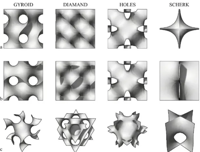
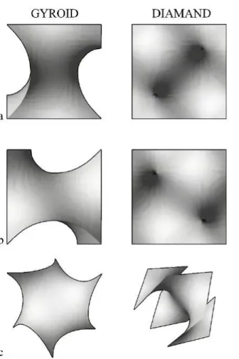
The minimal surfaces to be researched in the scope of the case study selected according to four parameters. The parameters determined to highlight the architectural potential of the selected minimal surfaces are the volumetric potential, modularity, continuity, and variability. Considering the parameters, selection made among the minimal surfaces within the MathMod software. In the first place, four minimal surfaces selected as Gyroid, Diamand, Sherk, and Holes. The variation potentials of selected minimal surfaces have been researched and listed by changing in equations. As a result of the selection, Gyroid included in the case study due to the fundamental curve.
3.1. Digital Modeling
Computer Programs
The first stage of the case study is choosing minimal surfaces, which consist of the value ranges to be given to the equation in the computer program. Minimal surfaces that form by equations are variable and expandable systems. In this research, MathMod used as a visual program to understand variation and chose minimal surfaces.
Another issue is to choose the parametric modeling and robot control software. Parametric modeling and robot control preferred to be generated in the same software for avoiding the possible errors. The motion route created in the computer program must be converted to KRL code for the robot to understand. The selected computer program needs to be able to translate the design created in the digital environment into the language required for production. Rhinoceros is a software that provides the needs of the digital design in this research with the plug-ins and add-ons. Digital visualization, modeling, and fabrication processes parametrically programmed in Rhinoceros 3D software and Grasshopper plug-in. Robots used as an add-on program of the Grasshopper that can simulate the industrial robot in the program and convert
22
the motion path to the format language required for production. Creating surfaces with the equation is an important step in the research. For that, the Millipede add-on used.
Minimal Surface Variations in MathMod
TPMS are generating with mathematical equations. By varying the parameters contained in the equations, the surfaces are varied. There are two groups of variables in the equations. One is the unknown in the equation, such as x, y, and z, and the other is the Domain range of values given to those unknowns. The number range controls the number of units arranged. With the changes made in the unknowns of the equations, the unit size in X, Y, and Z-axis controlled.
The surface variations formed by the changes made in the equations and number ranges of the selected surfaces researched with the MathMod software and lists created for each minimal surface. Gyroid cubic unit cell generates when equation domains of the unknowns limited between -4 and 4. Limiting unknown domains between -1 and 1 generates a fundamental unit. Without making any changes in the equation, limiting each unknown domains in different range causes the minimal surface to extend. With the unknown X limited between -4 and 16, and unknowns Y and Z limited between -4 and 4, surface extends through X direction (Figure 3.1. (c)). Multiplying the Z unknown with 5 and defining with the same range creates a stretched surface (Figure 3.1(f)). Other variation lists created by using different minimal surfaces (Figure A.1., Figure A.2., Figure A.3.).
23
24
Creating TPMS by Equation
The first definition of creating the minimal surfaces in grasshopper reference from diploma studio 10 at Westminster University School of Architecture website (URL-29). The definition was created by using Iso Surface from Millipede add-on.
Definition;
Figure 3.3. Minimal surface generation code by equation
Component Index and Parameters of the Definition
Panels used for texts of the equations of the minimal surfaces. Chosen minimal surface
equations integrated into the file with panel components. They use the input value of the
Evaluation components’ F input.
Evaluate creates a list by placing the values assigned to the unknowns by X, Y, and Z inputs in
25
The output of the Evaluate component, which is R (Result), connects with the V (Values) input of the Iso Surface component.
The output of the Range component converted into three separate lists with Cross Reference as A, B, and C and connected with the X, Y, and Z inputs of the Evaluate component.
To define the bounding box of the minimal surface Domain Box component used. A number slider connected to the X, Y, and Z inputs to specify the edge values of the box. The output of the Domain Box (B) connected with the B input of the Iso Surface component, which is in
Millipede.
The range component used for placing the defined number of points with the N (Steps) input
in equal intervals in specified limits. Expression of the N input needed to be changed as x-1. To specify the limits, Domain component used. A and B inputs of the Domain component specify the limits of the unknowns in the equation, for example -1.00*pi < x,y,z < 1.00*pi
The three-dimensional grid resolution defined with the Xres, Yres, and Zres inputs of the Iso
Surface. N (Number) input of the Range component connected with the Xres, Yres, and Zres
inputs for containing the minimal surface incorrect form to create the three-dimensional grid.
The minimal surface created by triangles and the resolution of them defined with Iso Value input of the Iso Surface by a slide.
Minimal Surface Variations in Grasshopper
Ex.1. Domain defined between -1 and 1;
• -1<x,y and z<1
• Contains in 30x30x30 cm3 bounding box. • The surface resolution is 20.
26
Figure 3.4. The outcome of the ex.1; generating minimal surface cubic unit cells in Grasshopper; (a) Top view
(b) Front view (c) Perspective view
Ex.2. Domain defined between -0.5 and 0.5;
• -0.5 < x,y and z <0.5
• Contains in 30x30x30 cm3 bounding box. • The surface resolution is 50.
27
Figure 3.5. The outcome of the ex.2; generating minimal surface fundamental patches in Grasshopper; (a) Top view (b) Front view (c) Perspective view
Robot and Running System
The digital fabrication robots have tools that do the primary job, such as the laser beam part of the laser cutter or the tip of the three-dimensional printer that puts the material on the counter. The movement of those robots controlled with defining a movement path and the tool center of the robot follows the path that the designer arranged for fabrication. In laser cut, the product divided into sections and placed on a representative plane as lines, which are movement paths of the laser beam. The same logic works on the CNC with a mill and 3D printers with the tip that material flows. Fabrication with the three-dimensional printer, it is necessary to determine the path that the tip follow. However, the three-dimensional form to be produced should be
28
divided into sections that connected and become a loop/ spiral and production made by following this loop.
Industrial robots have the same logic in three-dimensional space. However, the tool attached to the end-effector of the robot arm can be changed according to work. Therefore, unlike other robots, there is no fixed center point. The center of each tool must be calibrated before production with the robot arm, and the movement line should be drawn according to the tool. The tool center point of the robot arm is called Tool Center Point (TCP). The movement route of the robotic arm determined by the points that TCP will go through, the operations it will perform at these points, and the movement between points. The line of action can be created by teaching and programming. The movements of the robot arm can be simulated in a computer environment with the plug-ins of the Rhino program, Grasshopper, and Robots. At the same time, the movement line created in this program can be translated into the language that the robot will run.
In the research to be conducted in this thesis, the movement route will be formed in Rhino software with Grasshopper plug-in and simulated by Robots add-on. Istanbul Bilgi University laboratory consists of a KUKA KR 20 industrial robot as a robotic fabrication system.
KR 20 model designed as 6-axis jointed-arm kinematic systems and lift 20kg payload. It has 6 axes, and end-effectors are attached to the sixth axis (A6) (Figure 3.6. (a)) (URL-26). Robotic arms can work in a spherical area. Reaching dimensions of the KUKA KR20 robotic arm shown in Figure 3.6. (b) and (c).
Figure 3.6. (a) The direction of rotation of the KUKA KR20 industrial robotic arm (b) Work envelope, side view.
29
3.2. The Geometric Structure of Gyroid
The Gyroid is a TPMS that can extend infinitely without self-intersection. (Schoen, 1970) The Gyroid cubic unit cell has three subunits, and the smallest can form the other two. Each of these subunits is on different scales, and all three can be used for Gyroid production. A combination of two “fundamental regions” (Figure 3.7.d) creates a “fundamental patch” (Figure 3.7.c), and six fundamental patches combination create a “fundamental unit” (Figure 3.7.b). Eight fundamental units create a Gyroid cubic unit cell. The fundamental region of Gyroid is 1/96 of the cubic unit cell of it. (Gandy & Klinowski, 2000; Schoen, 1970) In this research, the expected outcome of the case study is understanding the generating logic of a Gyroid composition called “unit cell” (Figure 3.7.a) and variation of it.
Figure 3.7. (a) The cubic unit cell of the Gyroid surface. (b) The fundamental unit. (c) The fundamental patch (d) The fundamental region
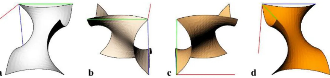
Triply periodic minimal surfaces generally have symmetry axes as their three-dimensional extending system. According to Schoen, Gyroid does not contain linear and planar symmetry axes. It does not have mirror reflections either. (Schoen, 1970) Some rotation sequences that generate the Gyroid surface. However, because of its geometry, after the rotation, several units become mirror reflections of each other.
The cubical unit cell of Gyroid can be obtained by four different rotations of the fundamental unit. If one of the rotated fundamental surfaces selected as the reference surface, the other three needs to rotate three different axes and angles. Rotating the fundamental surfaces can be complicated. Therefore, a three-directional line system added to the fundamental unit for
30
navigating the rotating units. With a three-directional line system, positions, rotating angles, and axes are better understandable.
Figure 3.8. Rotations of the fundamental units in the Gyroid cubic unit cell. (a) The reference fundamental surface for rotating; G. (b) G1 (c) G2 (d) G3
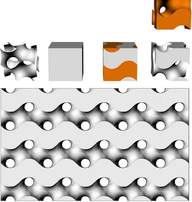
There is no strict evolution system for creating a Gyroid surface. In this research, these four rotated fundamental surfaces used for the evolution of the Gyroid cubic unit cell. They also can be used for three-dimensional extrusion.
Figure 3.9. Evolution of the Gyroid cubic unit cell
TPMS split their boundary volume into several spaces generally called “labyrinths”. The Gyroid cubic unit cell has two independent, non-intersecting labyrinths, which are mirror-symmetric to
31
each other. (Schoen, 1970) The volumetric module in this research is created from the Gyroid cubic unit cell surface to split the solid bounding box into two systems.
32
3.3. Parameters of the Cutting Wire
Form to be Cut
Gyroid can be generated in various ways, as mentioned above. In order to cut the Gyroid with a straight wire, multiple carving movements are required. In the case study, the unit intended to be cut with a single cutting motion. Fabricating Gyroid fundamental unit is not seem possible without carving. Because of two fundamental regions creates a fundamental unit, fabricating a fundamental region would be repeating the same movement twice. Therefore it is decided to fabricate the fundamental unit of the Gyroid.
Wire Form
If a straight wire used for cutting, as shown in (Figure 3.11), the cutting route followed by lines not touching the surface of the unit to be cut. Since it is not possible to cut with straight wire in one movement, cutting with curved wire is considered. It predicted that the curve which will form the hotwire cutter should be the Gyroid fundamental curve.
33
Figure 3.12. Edge curves of the Gyroid fundamental patch
Each edge of the Gyroid patch is the same curve in different positions as a curve, a mirror of the curve, and rotation of them. Preparing a wire with a fundamental curve and mirror of it is necessary to fabricate Gyroid.
Figure 3.13. Wire form
Figure 3.14. The active section of the wire moves from point 1 to point 2
The active cut section of the wire changes at every moment of movement. The active cut section starts at between the starting point and the middle point of the wire and proceeds through the central point and the endpoint of the wire.
In case of attaching the hotwire cutting tool to the robot arm, the center of the active cutting section should be defined as TCP. However, the active cutting section of the wire needs to be changed during the cut. In other words, the active section of the wire should be uncertain; therefore, the center and length of the active section on the wire constantly change. Two
34
different cutting methods can be followed in the scenario of attaching the hotwire cutter tool to the robotic arm. The first is to make TCP moveable during the cut. It would be hard to control, not precise, and complicated, but it is not impossible to do. The second is to fix TCP to the center of the wire and control the movement with reference points outside the material. That is to say, in the simulation prepared for the cut, the movement path of the TCP must extend beyond the EPS block. Since it is not possible to see the product in the simulation in rhino and grasshopper programs in this stage, it thought that it might confuse the definition.
Apart from attaching the hotwire tool to the robotic arm, creating a tool for attaching the EPS block to the robot. TCP can be defined as a fixed point if the material is attached to the robot in this scenario. By controlling the movement of the robot, it is possible to change the active cutting part of the wire, which would be fixed on the ground. In this case, the movement of the TCP can be ignored. It sufficient that the TCP is correctly identified on the surface of the material and that the path of the material designed according to the reference points to be placed around the wire. Because of these reasons, it decided to attach the EPS block to the robotic arm.
Figure 3.15. EPS holding tool dimensions in mm
The tool designed to attach the foam to the robotic arm. The foam and the unit holding the foam defined as a tool in the Grasshopper file. In this way, TCP can be defined at every point of the foam and changed as desired.
35
Figure 3.16. EPS holding tool attached to the robot
The Size of the Unit
The Foam units will be produced by cutting 60 cubes. The distance between the start and endpoints of the wire to be cut must be twice the length of the edge of the unit cube to which the fundamental unit is to be cut. When the distance increases, the deformation rate of the wire increases. Considering the cube size and the length of the wire, fabricating the fundamental unit from a 15 cm cube was decided. In this way, the entire 60 cubic styrofoam cube can be used, and there will be no remaining material. Every 15 cubes will be cut to fabricate a fundamental unit and a mirror. In this case, if the cuts made correctly, it is possible to cut 64 Gyroid fundamental units and 64 mirror units from the cube of 60.
The Gyroid fundamental unit fits into the 15-cube. Cutting with 15 cubes can damage the tool or wire attached to the robot. Therefore, the foam units will be cut and used in size 30x15x15.
Correct positioning of the base is essential for cutting 60cm cubes of EPS. The slope of the surface on which the 60cm cubes will be placed must be known in the code to be written for each unit to be the same dimensions.
Units were consisting of prisms of 15x15x30 cm3 cut from cubes of 60x60x60 cm3. 32 units obtained by cutting the cube to the specified dimensions.
36
Figure 3.17. EPS unit blocks
The dimensions of the units are a few mm less than 15x15x30 due to the melting of the foam while cutting with the hot wire cutter.
3.4. Initial Tests of Robotic Hot-wire Cutting
Before cutting Gyroid with the robotic arm, several wire and material experiments have been made. The experiments prepared to decide the density of the EPS foam, the thickness of the wire, and the value of the power supply for heating the wire.
EPS foam will be used as a material. The foam will be cut in the form of the fundamental unit by the curved hot wire by melting. Because of the heat and the thickness of the wire, there will be a melting range. EPS foam should be in the ideal density to minimize the melting range.
Wire thickness is an important parameter for cutting. It needs to be in the ideal thickness for the melting range, steady, and heating. The EPS foam is going to be cut by the wire, which is heated by current electricity. The wire should be shaped in the Gyroid fundamental curve while cutting and not deform while heating and cutting the EPS foam.
For thickness and density experiments, a simple mechanism set up. In the first place, the thickness of two-wire and two EPS densities tested manually. After deciding wire and material,
37
speed and heat experiments have been done with the industrial robotic arm. The power supply used for the mechanisms is the one available in the fabrication laboratory, which has values of 30 Volts and 10 Amps maximum.
The thickness and Density Experiments
Two different types of wires and EPS foams tested in this phase. For the wire, a non-magnetic alloy of nickel and chrome, which called Nichrome wire, used in different thicknesses as 2 mm and 0,9 mm. Nichrome wire has a high resistance to oxidation at high temperatures.
The mechanism set up for the experiments, made by a woodblock and wire. The cutting wire is 36 cm long and 2 mm thick. When the 2 mm thick nickel-chrome resistance wire is attached power supply, the power supply's power is 12.7 V 10.1A at maximum. In the first test with 2mm diameter Nickel-Chrome wire, two foams with different densities cut. The cutting speeds of the foams, the resistance to the wire, and the melting rate of the material are different for different EPS witch have different densities.
Figure 3.18. Experiment tool for wire and power supply
For the EPS foam, two different foam used in different densities which are 20 kg/m3 and 13 kg/m3. Between them, particles of the low-density foam are bigger and easy to cut by hand. High-density foam is heavier than low-density foam, yet, it has more resistance to pressure. The melting thickness of the low-density foam was recorded 2 mm more than high-density foam as
38
5mm to 3 mm. In addition to that, the fumes exiting by melting with the heated cut is observed more with low-density foam. Therefore, it decided to use more dense EPS foams for fabrication.
Figure 3.19. Wire and EPS density experiment
The foam melted during cutting remains on the wire as a layer (Figure 3.19). After a few cuts, the thickening layer can lead to sensitivity problems with the wire. In order to reduce the melting rate of the foam in the cutting, it necessary to increase the cutting speed or reduce the heat at a constant speed. It projected that increasing the speed in the section where the form of the wire remains intact will damage the wire. For this reason, it will be more accurate to increase the temperature for cutting with 2 mm thick wire. In order to increase the temperature of the wire, a high power supply required. However, the increase in heat is also a factor that will increase the melting rate of the foam. Increasing the melting rate may prevent the final product from being fabricated correctly.
0.9 mm thick Nichrome wire can be used for cutting with less melting. It observed that the thinner wire compared to the previous test did not deform during cutting but bent according to the speed of movement of the material. The correct speed and heat ratio must be defined in order to complete the cut without deformation.
Speed and Heat Experiments
Another hot-wire cutter tool made for speed and heat experiments with the industrial robotic arm. After the tool set up, the new hot-wire cutting tool model made in the Rhino file for creating
39
the movement path in grasshopper. The material was attached to the robot arm for cutting speed tests.
Figure 3.20. Experiment tool for speed and heat
For this experiment, support units prepared to stay fixed on the table placed in front of the robot to hold the wire. The supports are round 2 cm thick wooden bars. The wire placed in the holes drilled in the centers of the rods bends 5 cm higher than the centers to form a Gyroid curve. For heating the wire, the conductors of the power supply connected to both sides of the 2 mm thick wire.
The length of the wire is one of the parameters of the heating speed and deforming against externally applied forces. Since the fundamental patch intended to be cut from 15 cm cubes, the projection of the wire should be 30 cm. If 5 cm units wanted to be cut, the projection length of the wire would be 10 cm.
Figure 3.21. First experiment and result