T.C.
BAHÇEŞEHĐR UNIVERSITY
TEAM
SUMO
Master’s ThesisERĐNÇ TOPDEMĐR
ĐSTANBUL, 2008T.C.
BAHÇEŞEHĐR UNIVERSITY
INSTITUTE of SCIENCE
ELECTRICAL & ELECTRONICS ENGINEERING
TEAM SUMO
Master’s Thesis
ERINÇ TOPDEMĐR
Thesis Advisor: ASST. PROF. H. FATIH UĞURDAĞ
T.C.
BAHÇEŞEHĐR UNIVERSITY
INSTITUTE of SCIENCE
ELECTRICAL & ELECTRONICS ENGINEERING Name of the Thesis: Team Sumo
Name/Last Name of the Student: Erinç TOPDEMĐR Date of Thesis Defense:
This thesis has been approved by the Institute of Science.
Prof. Bülent ÖZGÜLER
Director I certify that this thesis meets all requirements as a thesis for the degree of Master of Science.
Asst. Prof. Bülent BĐLĐR Program Coordinator
This is to certify that we have read this thesis and that we find it fully adequate in scope, quality and content as a thesis for the degree of Master of Science.
Examination Committee Members Signatures
Asst. Prof. H. Fatih UĞURDAĞ --- Asst. Prof. Bülent BĐLĐR --- Asst. Prof. Yalçın ÇEKĐÇ ---
iii
ACKNOWLEDGEMENTS
I first wish to thank Asst. Prof. H. Fatih UĞURDAĞ for his continuous encouragement and assistance of every kind throughout this study.
I also wish to thank my thesis buddy, M. Cihan EĞĐLMEZ, for his help especially in the research process of the project from various sources and the Internet.
I also wish to thank my dearest friend Betül ERDOĞDU for her unlimited support in every stage of my life and for the inspiration and courage she gave me in this work. I also thank Res. Asst. Duygu ÇAKIR, the Bahçeşehir University Robotics Team, especially A. Seçil GÖKÇEOĞLU, for their support and encouragement all along this work.
Last but not least, I wish to thank all of the faculty members at Bahçeşehir University, as well as my family and all my friends for their patience, support, and love.
iv
ABSTRACT
TEAM SUMO
TOPDEMĐR, Erinç
Electrical & Electronics Engineering
Advisor: Asst. Prof. H. Fatih UĞURDAĞ
August 2008, 63 pages
In our country and on all over the world, there is an increase in the number of robot competitions and competitors. Sumo Robot Challenge is one of these categories, and it also has some subcategories. Team Sumo is a new alternative to Sumo Robot.
In Team Sumo, two robots (friends) are sumo-wrestling against a single rival robot (foe). The project involves both algorithm development and robot implementation. The objective is to steer the friend robots in a cooperative way and defeat the foe robot. Instead of putting vision or intelligence in the friend robots, they are just controlled by a computer with a camera over the ring.
The reasons why this topic is chosen as a master’s thesis are the increasing number of studies and related technologies in “mobile robots” all over the world but on the other hand only a few in our country. Also this is a topic that uses machine vision, which combines robotic applications with computer vision. The objectives of the project are to track multiple robots in real-time using a video camera, detecting each of mobile robots, deciding movements, and wireless communications for movement commands. The video camera is positioned above the ring. The video feed from the camera is analyzed in real time and the robot positions are determined by our software. The
v
software is written in C++ using OpenCV, which is an open source library developed by Intel. The wireless communications is implemented with RF signals at 433 MHz. The robots are small LEGO Mindstorms vehicles that are moving inside a ring. Friend robots consist of only DC motors, motor driver chips, RF receiver, and a PIC microcontroller.
Keywords: Robotic Vision, Machine Vision, Computer Vision, Mobile Robots, Object Tracking
vi
ÖZET
TEAM SUMO
TOPDEMĐR, Erinç
Elektrik – Elektronik Mühendisliği
Tez Danışmanı: Yrd. Doç. Dr. H. Fatih UĞURDAĞ
Ağustos 2008, 63 Sayfa
Ülkemizde ve dünya robot yarışmaları ve yarışçılarının sayısı günden güne artmaktadır. Bu yarışmaların kategorilerinden biri de Sumo Robot Yarışması’dır ve bu yarışmanın da kendine ait alt kategorileri vardır. Sumo Robot Yarışmaları’na, Team Sumo’ya yeni bir alt kategori olarak öneriliyor.
Team Sumo projesinde iki robot (dost), rakip bir robota (düşman) karşı sumo güreşi yapmaktadırlar. Proje, hem algoritma geliştirme hem de robot yapımını içermektedir. Amaç düşman robotu yenmek için dost robotların birlik içinde hareketini sağlamaktır. Dost robotları kontrol etmek için işbirliği yapan otonom robotlar kullanmak yerine robotlar sadece bilgisayara bağlı bir kamera tarafından kontrol edilmektedir.
Bu konu yüksek lisans tezi olarak konu üzerinde yapılan artan çalışma sayısı ve hareketli robotlar üzerine yapılan çalışmaların dünyada artması, fakat ülkemizde yeterli sayıda olmamasından dolayı seçilmiştir. Ayrıca bu konu robot uygulamalarını ve bilgisayarla görme konusuyla birleştirmektedir. Projenin hedefleri, video kamera kullanarak birden çok robotu gerçek zamanlı olarak takip etmek, hareketli robotların herbirini ayrı ayrı bulmak, hareketlerine karar vermek ve hareket komutlarını kablosuz
vii
haberleşme yoluyla aktarmaktır. Video kamera piste yukarıdan bakmaktadır. Kameradan gelen görüntü gerçek zamanlı olarak analiz edilir ve robot pozisyonları buna göre geliştirilmiş olan yazılımla belirlenir. Yazılım C++ programlama dilinde OpenCV isminde Intel tarafından sunulmuş açık kaynak kodlu bir kütüphane kullanılarak yazılmıştır. Kablosuz iletişim 433 MHz’de RF sinyalleri kullanılarak yapılmıştır. Pist içinde hareket eden robotlar küçük LEGO Mindstorms araçlarıdır. Dost robotlar DC motorlardan, motor sürücü entegrelerinden, RF alıcılarından ve bir PIC mikrodenetleyiciden oluşmaktadır.
Anahtar Kelimeler: Robotik Görme, Bilgisayarla Görme, Gezgin Robotlar, Nesne
viii
TABLE OF CONTENTS
ACKNOWLEDGEMENTS ... III ABSTRACT ... IV ÖZET ... VI TABLE OF CONTENTS ... VIII LIST OF TABLES ... X LIST OF FIGURES ... XI ABBREVATIONS ... XII 1. INTRODUCTION ... 1 2. PROBLEM DEFINITION ... 4 2.1 THE SOFTWARE ... 7
2.2 THE WIRELESS COMMUNICATIONS ... 7
2.3 THE HARDWARE ... 8
3. LITERATURE SURVEY ... 9
4. HARDWARE ... 12
4.1 MECHANICAL HARDWARE ... 12
4.1.1 Common Mechanisms in Robotic Applications ... 13
4.1.2 Sumo Robots ... 14 4.2 MAKING ROBOTS ... 16 4.3 ELECTRONIC HARDWARE ... 18 4.3.1 Wireless Communications ... 18 4.3.2 PIC Programming ... 24 4.3.3 Motor Control ... 26 4.3.4 Electronic Assembly ... 27 5. SOFTWARE ALGORITHMS ... 31 5.1 OPENCV ... 31 5.2 PIC BASICPRO ... 31 5.3 ALGORITHMS ... 32 5.3.1 Color Detection ... 33 5.3.2 Milestones ... 39 5.3.3 Movement Algorithm ... 45
ix
5.3.4 The Main Program ... 47
6. CONCLUSION & FUTURE WORK ... 49
REFERENCES ... 51
APPENDICES ... 54
APPENDIX 1 – PICTURES A.1- PRINT SCREENS ... 55
APPENDIX 2 – SOFTWARES A.1 - DESCRIPTION OF OPENCV AND ITS INSTALLATION ... 57
APPENDIX 2 – SOFTWARES A.2 - INSTALLING PIC BASICPRO ... 61
x
LIST OF TABLES
Table 4.1: RS-232 Pin Definitions ... 19
Table 4.2: Look-up Table for Orders ... 25
Table 4.3: H-Bridge Truth Table ... 27
xi
LIST OF FIGURES
Figure 2.1: System Layout ... 6
Figure 4.2: RS-232 Voltage Waveform ... 19
Figure 4.3: RS-232 DB-9 Connector ... 19
Figure 4.4: USB-to-Serial Port Adapter ... 21
Figure 4.5: Transmitter Module and Pins ... 22
Figure 4.6: Receiver Module and Pins ... 22
Figure 4.7: Schematic of Transmitter Circuit ... 23
Figure 4.8: Schematic of Circuit on the Robot ... 24
Figure 4.9: H-Bridge Circuit ... 26
Figure 4.10: L293D Pin Connections ... 27
Figure 4.11: Printed Circuit Board of Circuit on the Robot ... 28
Figure 4.12: Soldering Circuits of Robots ... 29
Figure 5.13: PIC Programming Overview ... 32
Figure 5.14: HSL Color Space and Hue Scale ... 35
Figure 5.15: Algorithm for Choosing Threshold Values ... 36
Figure 5.16: The Global Reference Frame and the Robot Local Reference ... 41
Figure 5.17: Screens from Original Image and Results ... 42
Figure 5.18: Movement Calculations of the Robot ... 45
Figure 5.19 Project Cycle... 47
Figure App. 1.20: Print Screen of Single Robot Control with Target Following ... 55
Figure App. 1.21: Single Robot on Action ... 55
Figure App. 1.22: Two Friend Robots with Target Robot in Action ... 56
Figure App. 2.23: OpenCV Installation Screen I ... 58
Figure App. 2.24: OpenCV Installation Screen II ... 58
Figure App. 2.25: OpenCV Installation Screen III ... 59
Figure App. 2.26: Adding Environment Variable to the System ... 59
Figure App. 2.27: Adding OpenCV Libraries to MS VC++ 6.0 ... 60
Figure App. 2.28: Importing PBP to MPLAB IDE ... 61
Figure App. 2.29: Putting Path to System Environment Variables ... 62
xii
ABBREVATIONS
Alternative Current : AC
Amplitude Modulation : AM
Amplitude-Shift Keying : ASK
Direct Current : DC
Federation of International Robot-soccer Association : FIRA
Frame per second : fps
Frequency-Shift Keying : FSK Graphic User Interface : GUI
Integrated Circuit : IC
Integrated Development Environment : IDE
Mega Hertz : MHz
Mega Pixel : MP
Microsoft : MS
Open Source Computer Vision Library : OpenCV
PIC BasicPro : PBP
Peripheral Interface Controller : PIC
Radio Frequency : RF
Received Data or Receiver : RX
Red-Green-Blue : RGB
Transmitted Data or Transmitter : TX Universal Synchronous/Asynchronous Receiver/Transmitter : USART Universal Serial Bus : USB
1.
INTRODUCTION
Robotics has achieved great success in the world of industrial manufacturing. These commercial robots suffer from a fundamental disadvantage of lack of mobility. They have a limited range of motion. In contrast, mobile robots are able to travel, so they are more effective. This work focused on some small robots which are for research and education to achieve robust mobility with vision perception using some computer vision techniques. Also provides an introduction to aspects of mobile robotics, including software and hardware design considerations, related technologies, and algorithmic techniques.
The goal of the project is to track multiple mobile robots in real-time using a video camera and control them with RF (Radio Frequency) via a computer. More specifically, it is a new approach in sumo robot competition with three robots instead of two. Two of these robots are friends and the other is the foe. The foe one is a sensor based, a self-controlled sumo robot. The friend robots are smaller than the foe and they are sensorless, dummy robots. They are controlled by a host computer. The video camera is positioned on the ceiling above the area on which they fight with each other. The frame feed from the camera is analyzed in real time and the positions of robots are determined. Depending on frame, next moves of the robots are decided.
The reasons to choose this topic as a master thesis are the increasing number of studies and related technologies in “mobile robots” all over world, but few in our country. Also this is a topic that uses machine vision, which combines robotic application followed by computer vision, will be the most important requirement for control and automation technology.
The related studies in autonomous mobile robots include keywords like planning, navigation and localization, which are mostly about “path planning or map building”. It is also possible to see advance mobile robotics researches in robotics competitions as a category of “soccer robots”. There are so many competitions and sub categories for soccer playing robots, but none in Turkey. The main idea is similar with the one in this
2
work, including observing area and robots, deciding and/or estimating next move, and controlling the robot or robots with wireless communications.
All these reasons mentioned above represent the importance of this thesis. First of all, it is a new approach in sumo robot competitions, which is an unattended team robot application. It is also a modular application that can be used in many other robotic applications with a few changes. As in the project: colored object tracking to multiple colored object tracking, single robot motion controlling to many. The final aim of the project is “Team Sumo”. In Team Sumo, two robots (friends) are sumo-wrestling against a single or multiple rival robots (foe). The objective is to steer the friend robots in a cooperative way and defeat the foe robot. Instead of putting vision and/or intelligence in the friend robots, they are just controlled by a computer with a camera. The hardware of the project includes both mechanical parts and electronic circuits of the robot. The electronic part consists of wireless communications, and DC motor control. Wireless communication will be made by a transmitter and receiver module. PIC microcontroller on the robot receives data from the receiver that is already connected. RS-232 interface is used to send data through transmitter from computer. Wireless communication is done at a frequency of 433MHz. PIC reads the data, which includes the information about the action of the robot. PIC controller also controls the motor driver due to orders from wireless transmitter. The mechanical parts are, body of the robot, gears, DC motors, wheels etc. LEGO® Mindstorms® is used to make these parts. The reason Lego® is used in this project is because it is very flexible and easy to create, re-create, and modify.
The software part of the project will be the heart of the thesis, as any other vision process. As a scientific discipline, computer vision is concerned with the theory for building artificial systems that obtain information from images (http://en.wikipedia.org/wiki/Computer_vision May 25, 2008). The whole project becomes a machine vision project; while the software part can be seen as a computer vision. The source of the images will be the camera, which is above the area robots placed. It will be connected to a computer and transfer the images it collects. The algorithm will process the images and decides the robot how to act. The main control software part of the system consists of a program written in C++. Microsoft® Visual
3
Studio 6.0 with OpenCV library is used to develop our program. The OpenCV Library is mainly aimed at real-time computer vision, whose performance can be significantly enhanced on the Intel® architecture. The OpenCV Library is a collection of low-overhead, high-performance operations performed on images (OpenCV Reference Manual 99-00, pp.1-1). The written program can be used in any computer by attaching the required .dll files. The camera is also another important part of the project, as in all vision projects. We use a Logitech® 1.3 MP Webcam, because it is cheap and easy to use. But it also has some limited usage, like maximum pixel size, frames per second (fps) etc.
In the next chapter of this thesis, problem definition of the project and its working principles are explained. It is explained that what answer is searched in this project. The main parts that made the project and how these parts work together are explained simply.
In the third one, literature survey and other studies are shown. Related researches in robotics world, image processing, and machine vision are explained simply.
In the fourth chapter, the mechanical parts and the designed electronic boards’ compose the hardware chapter. Common mechanical parts of a robot and their working principle are explained in detail. Types and rules of sumo robots are also explained. The electronic circuits for wireless communications, motor control unit and PIC microcontroller are also described in this chapter.
Fifth chapter explains the software algorithms and the interfaces that are used. The methods and procedures to solve problem and control the robot are also given in this chapter. Used software interfaces and installation of external libraries and compilers explained shortly.
In the conclusion chapter, final results from the thesis, benefits, future modules, and suggestions are included.
4
2.
PROBLEM DEFINITION
In this chapter, the problem that mentioned is defined precisely. The relations between system parts are given in detail.
This project aimed an autonomous mobile robot application, which is controlled in real-time. Computer controlled mobile robots with wireless communications used in “Team Sumo” application. The robots are autonomous, remote controlled small robots. The project is also seems like an object tracking application, because some tracking algorithms are used. So, as these parts are combined together, the whole work became a machine vision project.
Using a team of vehicles to accomplish an objective can be effective for problems involving a set of tasks distributed in space and time. To achieve effective solutions, in general, a vehicle team needs to follow a cooperative policy including non-communicative multi-robot coordination (Earl M. G., & D’Andreab R. 06). But the robots have a common network. The advantages of common networks can be and already have been used within robotics. A network between the groups of mobile robots allows communication between a robot and a host PC. (Schmitz C. 05).
In very beginning of the project, it considered that a camera had placed on each friend robot. The process and control unit also take place on the robot. This could be slow, inefficient and expensive solution. So, it is decided that putting camera above the area that robots move. This brings many advantages. Because, PC provides higher computation performance, Monitoring robots is easier on a PC rather than on a microcontroller. Also, remote control program running on a PC allows full control of any robot.
Although, single acting robots are still more common than multi-robot systems and can be found in a wide range of applications nowadays, there are several reasons for choosing two friend robots against one big foe robot instead of one vs. one. Reliability is one of them. The functionality is not based on only one robot. Therefore, if a single robot fails in the group, the task can still be processed by the other robot. Performance
5
is another reason. Tasks may be processed faster by several robots rather than by a single robot.
The work includes object tracking procedures in general. The system must follow positions of own robots, which were two well-defined objects. It also must follow position of the opponent, which was the one undefined object. The background is constant and also pre-defined. Tracking for the friend objects, color identification (or segmentation) is used as one of the most used methods in object tracking. The other methods, that usually used, are pattern recognition, motion estimation, and multi camera solutions.
Color segmentation is very difficult process as it dependent on environment light. Without light there are no colors. But the condition of light makes color identification too unpredictable. Pattern recognition and motion estimation methods need too many calculations. They could be slow and inefficient for the real-time work.
Some solution could be using a second camera. Then one is used for searching friend robots, which use IR Led to identify, with an IR filter. Other is used for the foe robot and the background. IR filter is used to detect just IR Led pattern. But with a CMOS camera it is not easy to detect IR light. Some other solution is reducing color maps, which is done by giving same color ID to similar colors, especially in HSV or YUV color spaces. After reducing blob analysis could give better results.
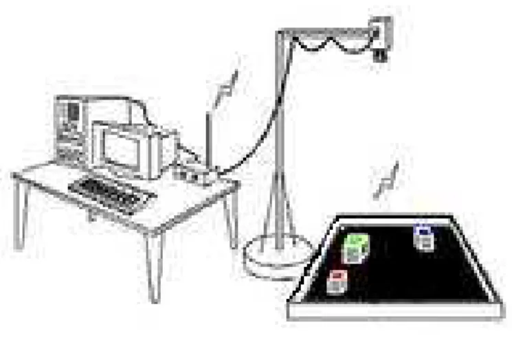
As the parts of the system had to be explained in detail, the project consists of three main parts. These are the software runs on computer, the wireless communications between computer and the robot, and robots’ hardware. The layout of the system is given at below figure.
6
Figure 2.1: System Layout
As it is shown in above figure, the robots and target are placed on the area. For all steps same test area, which is called dohyo in sumo robot competitions, is used. Dohyo has a black background with white border. The size can differ, usually a circle in shape. For the tests, a rectangular area, made of carton with size of 70 cm x 140 cm is used. The camera placed above of the area. And also there is a wireless communications between own robots and the host PC.
The webcam is set depend on ambition lighting. The template programs are used to set threshold values of white, red, orange, blue and other colors used on robots or as target. The main program takes a frame of that moment and finds objects depend on their colors. Three different modules are written so far. These are demonstrating different steps in mobile robot technology.
The first module controls single mobile robot inside the area. The aim is to move robot randomly inside the area not allow it going outside. Second one obeys rules in first module, but moves not at random. It moves pre-defined target. If the target placed inside the area, the robot moves along it and stops. If placed outside then moves closest distance to target inside the area. And the third one inherited from the second one, but more difficult. In this module there are two robots inside the area and they go to target as well.
7
2.1 THE SOFTWARE
The software is written at C++ programming language, using Microsoft® Visual Studio 6.0 as Integrated Development Environment (IDE). A webcam is also attached to computer from USB port. The software grabs an image from the webcam, process it depend on some algorithms, determines the robots and background, then decides what to do. The result is next move of the robots. These results send to communication board via RS-232 protocol.
C++ is used, because it is fast and easy to develop besides other programming language. As the thesis seems like a machine vision project, high level vision software like HALCON® or advanced engineering software like MATLAB® could be used. But they are either slow, need a framework, not free to use, or reduce the performance of the computer. The system works in real-time, so it has to be fast. So, C++ with OpenCV image processing library is used. OpenCV contains all the functions that are commonly used by image processing procedures.
Some setups like auto white balance, color boost, etc. for webcam are also done on the software part, when the system is initializing.
2.2 THE WIRELESS COMMUNICATIONS
In the software part, position of the friend robots and the target are detected then the written algorithm decides the next movement of robots as a result. These results send to robots via wireless communications with RF at 433 MHz. The transmitter board is attached to computer. The computer sends data using RS-232 protocol. This protocol can be used by serial or parallel port. In the project I used a notebook computer, which does not have serial or parallel port any more. So, an interface cable that converts USB to Serial Port is used. By this interface cable, the USB port turns into a COM port. At the communication board there is a female serial port input to take data. It is connected to a RF transmitter. The data send via antenna. There is also a voltage regulator on the board for transmitter to work properly. On the robot, the RF receiver is attached. Its digital output is connected to PIC microcontroller on the robot. The MAX232 IC, which regulates the voltages between EIA-232 protocol and TTL/CMOS, is not required to use by limiting the current.
8
2.3 THE HARDWARE
The hardware part contains both electronic parts and mechanical parts. Electronic circuits used for wireless communications and motor control at this project. Communication board described at below session. Two DC motors are provided the motion of the robot. These motors drive by H-Bridge circuit. Since two motors are used to drive the wheels of the robot independently, there is a need for two H-bridges. Instead of implementing self designed H-bridge control circuit twice, an alternative is to use an integrated circuit (IC), which provides more than one H-bridges. One such IC is L293D, which has two H-Bridges in it. It can supply 600mA continuous and 1 2A peak. The current absorbed by each motor is less then 600 mA. This gives me advantage of using an H-Bridge IC, instead of making one. Motor driver is controlled by PIC microcontroller. Speed of the robot controlled by mechanically, because it is easy with LEGO® parts. So, a PIC16F84A, which is a common PIC microcontroller, is enough for this demonstration. The PIC microcontroller is programmed by PIC BasicPro programming language. PIC part is also described in hardware part, because a specific circuit design is needed for PIC microcontroller. It will also describe in the hardware section in following pages.
The two motor located at each side of the robots. This provides a tank style rotation to robots. The motion is transferred from motor to wheels by different size LEGO® gears. The speed can be controlled by changing the size of the gears easily. Motors are located at center and each control two wheels at the same time. The body of the robot made of LEGO® Mindstorms® kit. It is designed as symmetrically to hold its center of gravity at the center of robot. The robot is also strong enough to most light strokes. The battery pack and electronic board is mounted inside the robot. And a colored hat, which is for recognizing robot by software, is placed on top of them.
9
3.
LITERATURE SURVEY
This study can be classified as autonomous mobile robots and robotic vision in general. Mobile robots could refer a very wide research area. This study could be limited by co-operative non-intelligent mobile robots. The term non-intelligent refers here; that robots are remote controlled but depend on a software algorithm, not a human. The robotic vision is a combination of computer and machine vision in the robotic applications. It forms mathematical and software part of this study.
In the literature the related examples are mostly about “path planning or map building”. And in robotic world it is able to see this kind of researches in robotic competitions as a category of “soccer robots”. The results are published with the keywords of autonomous mobile robot planning, navigation and localization, and robotic vision for both.
There are so many competitions and sub categories for soccer playing robots, but none in Turkey. Sumo robot competitions are arranged from many organizations for many years. Team Sumo is a new approach, which combines these two categories together. The main idea is similar to each other, includes observing area and robots, deciding and/or estimating next move, and controlling the robot or robots with wireless communications. Robot Soccer is the most similar work to Team Sumo.
Robot Soccer, since the idea was born in 1995, in the Korean Advanced Institute of Science and Technology, has been an intriguing field of research for the Robotics and Artificial Intelligence community throughout the world. Robot Soccer is a multidisciplinary project, which involves in-depth knowledge in the fields of motor control using a microcontroller, radio communication, image processing and strategy programming. The teams are required to identify the robots and the ball by different colored patches pasted on the robots and the orange color of the ball. RoboCup, or the Robot Soccer World Cup, is an international research initiative designed to advance the fields of robotics and artificial intelligence by using the game of soccer as a substrate challenge domain. The long-term goal of RoboCup is, by the year 2050, to build a full team of 11 humanoid robot soccer players that can beat the best human soccer team on a
10
real soccer field (Stone 2007, p. 1). It’s better to survey previous studies to comprehend this work better.
Color identification is the main part of most work. There are so many methods used in the past and still today. For example in Manu Chhabra’s (2003) work background subtraction and Gaussian filtering to remove noise followed by instance based color identification algorithm to identify patches. HSV color space is mostly used to identify color. Depend on Stone (pp. 9-24), after the camera settings are done, steps that have to be followed are color segmentation, region building and merging, object recognition with bounding boxes, position and bearing of objects, visual opponent modeling.
There are also sensor-based mobile autonomous robots. Sensor dependent robots are the easiest to build and control, but in time they became incapable, because in the autonomous mobile robots, the most important activities are navigation and localization (Sim, & Little 2008) (Zivkovic, Booij, & Kröse 2006). If the working place is unknown and random, especially in mapping robots, a self placed vision system is required. Multi cameras require more memory, more process and slow down the system. With a single camera and single sight the results have a risk of high error. With a single camera in unknown environment it is best to use an omnidirectional stereo image (Spacek, & Burbridge 2007). They place a camera looking at a pyramid mirror. Other method is placing multi-camera to a pyramid. Most times a single camera that placed to ceiling is enough. The very first studies on this type of mobile robots are made by Sirota (2004), and some Swiss guys at Lausanne Polytechnic University. They mention that vision-based tracking is used in nearly all robotic laboratories for monitoring and extracting of agent positions, orientations, and trajectories (Lochmatter, Roduit, Cianci et. al.). They also develop robust tracking software called SwisTrack, which is tailored to research in swarm robotics and behavioral biology.
But if the problem and the area, that robot will action, is well defined than a single camera is enough. The robots used in competitions are can be categorized as this. The competition area is known before, so a top-head camera is a global solution. Top-head cameras are used mostly in robot soccer, which have worldwide supporters and developers but not in Turkey. Playing a soccer-like game with small mobile robots is not only great fun for technology fans but also great technical challenge and educational
11
experience. Numerous categories are open to competitors under the umbrella of two international championships: the RoboCup and the FIRA World Cup (Keeratipranon, Sitte and Maire 2003). A CCD camera is used to capture images for the “brain” software to carry out image processing and analysis and hence the position of this ball and other robots. After the robot grabbed the ball, communicate with the teammate to exchange the latest location each other. Then, the robot will decide to bring the ball to the goal or pass the ball to the team mate.
All these are use the same methods approximately for processing image. They classify pixels, find blobs, and find objects, track objects, and outputs. These steps are very well described by Weiss and Jesse (2004) and also by Lars Hildebrand (2004). There are also many methods for target detection and tracking. Histogram, color segmentation and geometry are used for robust real-time vision systems. Feature analysis, blob tracking followed by mean shift algorithms are the other methods used in real-time vision systems (Veeraraghavan, Schrater, and Papanikolopoulos 2006).
Another problem that is faced before is the multi vehicle control problem. To reduce the odometry error of a single robot system, cooperative strategies are generated and set of tasks to be completed are listed for each of robot. Some authors add additional global information sources like GPS to achieve greater accuracy (Wildermuth, & Schneider 2003) (Earl, & D’Andreab 2007).
12
4.
HARDWARE
The hardware of the project includes both mechanical parts and electronic circuits of the robot. The mechanical parts are body of robot, gears, DC motors, wheels etc. LEGO® Mindstorms® is used to make these parts. Lego® is used, because it is very flexible and easy to create, re-create, and modify. The electronic part mainly consists of wireless connection, and DC motor control. Wireless connection will be made by transmitter and receiver modules via 433MHz RF signal, which are connected with a PIC controller. PIC controller also controls the motor driver due to orders from wireless transmitter.
4.1 MECHANICAL HARDWARE
Building mobile robots, it should be consider the physical properties of creations, including their size, weight, and mode of transport. A robot that is too heavy for its frame, or a locomotion mechanism that doesn’t provide sufficient stability, will greatly hinder the usefulness of your mechanical invention. In this section it will described designing the locomotion systems for robots, which are mostly Lego bricks.
LEGO Mindstorms is a line of Lego sets combining programmable bricks with electric motors, sensors, Lego bricks, and Lego Technic pieces (such as gears, axles, and beams). The first retail version of LEGO Mindstorms was released in 1998 and marketed commercially as the Robotics Invention System (RIS). The current version was released in 2006 as Lego Mindstorms NXT. As the robotics field continues to expand and innovate worldwide, LEGO® Education is keeping pace with the launch of LEGO MINDSTORMS Education NXT, the next generation of educational robotics for schools. The new concept features new programming software and curriculum relevant activity materials (http://www.lego.com/eng/education/mindstorms/default.asp June 5, 2008).
As a result Lego became handy for robotic applications because it is very flexible and easy to create, re-create, and modify. The main structure of the robot is generally a wood, plastic, or metal frame, which is constructed a little like the frame of a house with a bottom, top, and sides. Ready-made toys can be used as the basis for more complex homebrew hobby robots. LEGO is even designed to create futuristic motorized robots
13
and vehicles. You can use the parts in the kits as is or cannibalize them, modifying them in any way you see fit. Because the parts already come in the exact or approximate shape you need, the construction of your own robots is greatly simplified.
4.1.1 Common Mechanisms in Robotic Applications
A robot is a mechanical artificial agent. It is usually a system, which, by its appearance or movements, conveys a sense that it has intent or agency of its own. For robotic engineers, the physical appearance of a machine is less important than the way its actions are controlled (http://www.robotbuilder.co.uk/forum/topic.asp?TOPIC_ID=968 June 2, 2008) So, a manual controlled machine could not be named as a robot, as it includes most of same mechanical parts as self-controlled mechanism. The mechanisms, that will placed in most robots, shown and described at below.
Chassis (Frame): it represents the body of the robot. All other parts, including running parts and unanimated parts, are attached to chassis or placed inside chassis. It can be made of metal, wood, plastic, fiber, or hybrid. In this work it is made of Lego bricks, including foe robot.
Wheels & Tires: these are facilitating movement or transportation. Wheel size is important for speed, and control at turning. Different types of tires can be used, depending on friction, and the area robot will used. A common Lego wheel of solid balloon model of 2857 is used, which has 20 mm width and 30 mm diameter.
Gears: A gear is a component within a transmission device that transmits rotational force to another gear or device. It can be used also for reduction. Depending on their construction and arrangement, geared devices can transmit forces at different speeds, torques, or in a different direction, from the power source. In the design of friend robots some combination of Lego 8-tooth gears, 16-tooth gears and 24-tooth gears are used to make a gearbox for reduction speed.
Pulleys & Belts or Chains: A pulley system is used for the same reason as gears, transmission or reduction. A belt and pulley system is characterized by two or more pulleys in common to a belt. This allows for mechanical power, torque, and speed to be transmitted across axes and, if the pulleys are of differing diameters, a mechanical
14
advantage to be realized. There is not much difference between belt and chain mechanism, belt is just much smoother than chain.
Mounting components: these components used for assembly other mechanical parts, motors, sensors, cameras, power supplies etc. Like screw, thread, bolt, worm, nut. Bearings: A bearing is a device to transmit motion between two parts, which rotates. It decreases the friction, and protects the connection parts.
Motors: an electrical motor used for to move robot or its arm. Mostly DC or servo motors used to convert electrical energy to mechanical energy. Step or servo motors also can be used for holding, lifting, gripping than moving. In the friend robots, Lego Technic Motor (model 43362) is used. It has 5.5 N.cm stalled torque, 340 mA stall current, and approximately 450 rpm at 9 V.
4.1.2 Sumo Robots
Before describing Team Sumo more detailed, it could be better to understand traditional robot-sumo or robo-sumo. It is sports in which two robots attempt to push each other out of a circle. Two robots are sumo-wrestling against each other. All robots are autonomous (self-controlled), and rules are strict to avoid harming rival or the area. The engineering challenges are for the robot to find its opponent (usually accomplished with infrared sensors) and to push it out of the flat area. A robot should also avoid leaving the area, usually by means of a sensor that detects the edge. The area is circular area; which is called dohyo, with black background, and white border on the side.
15
Sumo Robot is divided into classes fought on progressively smaller areas (http://en.wikipedia.org/wiki/Robot-sumo June 5, 2008):
Standard class robots may mass up to 3 kg and fit inside a 20 cm by 20 cm box, any height.
Mini-sumo: Up to 500 g mass, 10 cm by 10 cm, any height. Micro-sumo: Up to 100 g mass, must fit in a 5 cm cube. Nano-sumo: Must fit in a 2.5 cm cube.
Femto-sumo: Must fit inside a 1 cm cube.
The rules are approximately same in all type of sumo robot competitions, on all over the world. These rules are described as below (http://www.robotroom.com/SumoRules.html June 5, 2008):
Two self-controlled robots are placed in a ring. The robots try to avoid falling out or avoid being pushed out by the opponent robot. The first robot that touches outside of the ring loses the round.
The first robot to win two rounds, wins the match. Different robots compete one-on-one against each other throughout the contest. The robot that wins the most matches wins the contest. Autonomous Sumo robots are self-propelled and self-controlled, without tethers.
After positioning and starting the robot, no remote control, power, positioning, or other help can be provided. The robot must care for itself until the round ends. As long as all other requirements are met, Sumo robots can be made out of any material. They can use any type or size of electric motor or electric-powered locomotion. They can contain any kind of processor, electronics, sensors, or batteries desired.
At the start of each round, Sumo robots must not exceed a specified width and depth. The lack of a height limit is important to some builders, as they may stack up electronics, motors, and other parts that wouldn't otherwise fit. The lack of a height limit
16
combined with the ability to change orientation during a round provides for creative opportunities.
Crafty inventors build tall scoops atop their robots. The robots then fall down to make themselves longer than would be initially allowed. At all times, robot behavior must be non-offensive, non-destructive, and non-harmful to humans, robots, and the facilities. This is an immutable principle, even if the behavior is unintentional or not by design. During inspection (and at any time during the event), the judges may require safety changes or other modifications to meet the harmlessness requirement. Harmful robots are either not allowed to compete at all or are later disqualified if potential harmful issues are proven or revealed in battle.
Judges also examine to see if a robot's design is sufficient to survive the expected pushing, shoving, and physical rigors of competition. Suggestions may be made to avoid damage to the robot. A weak robot is usually allowed to compete at its own risk. During the contest, the judge must determine if a robot's failure was due to its own lack of durability. Failures due to exposed wires or unsecured or flimsy parts shall be the responsibility of the robot with such weaknesses.
4.2 MAKING ROBOTS
Before software tests began, a working robot has to be made. In general, the robot will be look like a sumo robot, but it will be a dummy one. It has to have a rigid skeleton, which contains bricks, connectors, beams, and axles, made of Lego. Electronics circuit is also designed and prepared after making the main frame of the robot.
If necessary to be more precise and specifically, a 4-wheel, tank like robot is made. Tank like robots have no steering wheels. It had two DC motors at each side (left and right sides). The motors, which are also Lego Mindstorms motors, placed at the center of each side. Motor drives two wheels at the same time, which means it has not front or back-wheel drive. So, it looks like a 4x4 drive robot. This gives an advantage of robust controlling. Because, sliding ratio is same for all wheels, assuming the friction is also
17
same by using same kind of wheels. This type of robots is called non-holonomic robots in literature (Siegwart, & Nourbakhsh 2004).
After the making of the chassis of the robot, batteries are placed. The chassis is made depending on size of the batteries, because batteries are usually the heaviest and biggest component. They also placed in a position that they cold easily recharge. Lego motors are powered between 6 V and 12 V. So, it is considered that 7.2 V batteries could be enough at first. But the robot could not reach enough speed and acceleration. And also batteries are becoming empty so quickly. Then they replaced by a group of eight piled rechargeable AA type batteries placed, which has more than 11 V at full charge. The robot now could reach high speed, and easily maneuver.
This time, the problem is speed of the robot could be fast from software process. If the position of robot change too much between the frames grabbed, then it means the process is slow. Implementing an algorithm that process faster could be difficult and takes more time. It is easy reducing speed of the robot. There are two way to decrease speed. One is by electronically, other is by mechanically. Changing the voltage to control speed of motor, result wasting in power, because more the voltage level decreases, the most speed decreases. The motor needs more current to start rotate, because of inertia. Another way is using modulated signal instead of changing voltage level. There are many examples of speed control circuits with PWM. Advantages and disadvantages of these circuits are explained in further part.
As a result it is decided to reduce speed by mechanically; on other hand speed will be constant. The speed will not need to vary. For the demonstration of the thesis, it is enough to work with a constant speed. Then the speed is reduced easily by changing gear ratio. Using a different combination of 8, 16, 24 and 40-teeth gears, the speed decreased by 1/3. Decreasing in speed means increase in torque, which is also an advantage in sumo robot competitions. The total torque of the robot increase approximately 1/3, other goes to friction between gears.
18
4.3 ELECTRONIC HARDWARE
The robots could categorize in two types as stationary and autonomous robots. If it is a stationary robot, then the wiring, powering, controlling would not be a problem. But when it comes to an autonomous robot these could be act as a tether. Controlling could be done by a microcontroller, which placed on self, decides actions depend on sensors. The purpose of the electronic hardware is to control robot motion via remote by a computer-self in this project. To realize this purpose the basics of wireless communications, microcontroller based motor control are described in following lines.
4.3.1 Wireless Communications
In this work, a fully electronic remote control receiver and transmitter used for control. It can be used the remote controller to activate all of the robot’s functions. Remote control systems that connecting a personal computer to the robot. Just typing on the keyboard or using a joystick for control, and the invisible link does the rest. RF, infrared, Bluetooth, zigbee are the types of wireless communications. They all difficult to use, they are complicated, needs lots of calculations and have different protocols. It is best to design own wireless communications circuit, but there is many modules at stores. They are cheap, easy to use and assembly. In this project, RF modules, RWS-434 and TWS-434 RX/TX pair is used. They communicate at 433 MHz, using AM modulation. The receiver receive data and send it to PIC microcontroller, it will described at further section. The transmitter receives data from computer via serial port using RS-232 protocol.
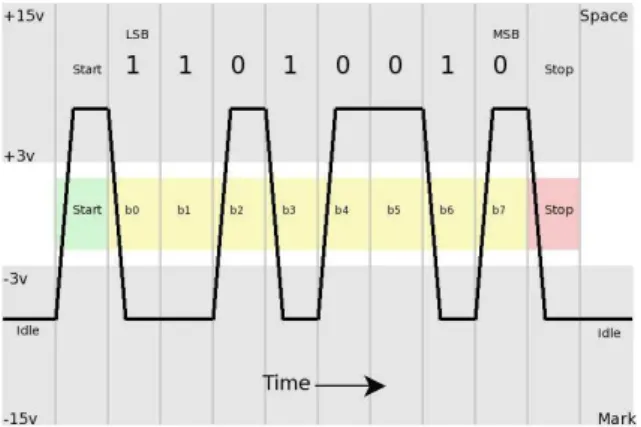
Serial port is designed for connect computers to other devices, like modem, mouse and keyboard etc. Serial port mostly produced at RS-232 standards. RS-232 (Recommended Standard 232) is a standard for serial binary data signals. It is designed for union between different types of communication devices. It defined from EIA at 1960. It sends or receives binary data at different voltage levels. Logic zero (0) differs from +3 V to +15 V and logic one (1) is differing from –3 V to –15 V.
19
Figure 4.2: RS-232 Voltage Waveform
At the beginning RS-232 standard defined for 25 pins. At modern computers, pins are removed, that are not required. The new 9-pin connectors (DB-9) are designed by IBM.
Figure 4.3: RS-232 DB-9 Connector
Serial port pin numbers and their definitions are given at below table. Use of a common ground is one weakness of RS-232. If the two pieces of equipment are far enough apart or on separate power systems, the ground will degrade between them and communications will fail; this is a difficult condition to trace.
Table 4.1: RS-232 Pin Definitions
DB-9 Pins DB-25 Pins Pin Definitions
1 8 Data Carrier Detect (DCD) 2 3 Received Data (RxD) 3 2 Transmit Data (TxD)
4 20 Data Terminal Ready (DTR) 5 7 Signal Ground (SG)
6 6 Data Set Ready (DSR) 7 4 Request To Send (RTS) 8 5 Clear To Send (CTS) 9 22 Ring Indicator (RI)
20
RxD and TxD pins are defined as receiving and transmitting data. DTR pin send ready signal to connected device. DSR pin receives signal when the data is ready at connected device side. SG is common ground; it is reference to other logic levels. RTS pin defines a request for sending data. CTS pin controls ready to receive commands or data for transmission. RI pin detects a ring signal from the telephone line.
Today serial COM ports are required for such things as radio control, rotor control etc. In new generation technology, USB ports are replacement for serial ports. Many new laptop computers and some desktop models are now being shipped without RS-232 serial ports and instead are equipped with USB ports. Because of this it becomes a problem to communicate Windows® (or any other serial communications software) over a USB port instead of a RS-232 serial port. Although USB stands for "Universal Serial Bus", the USB interface does not work anything at all like a standard RS-232 serial port. Like RS-232 serial ports, the USB ports on a PC are designed for interfacing external devices, however any device that is designed to connect to a USB port must come with a Windows "device driver" that essentially informs the operating system when the device is connected or disconnected to the PC and also provides a software interface to the device. A device driver is basically a small software program that provides a standard software interface to a particular hardware device. What this means is that practically any device could be designed to connect to a USB port as long as the device is supplied with a driver. The only problem with the USB interface design is that there is no way to simply open up a USB port and communicate with any device the same way that you can with a RS-232 serial port. Any software that communicates with a particular USB device must communicate with the device through the driver that is supplied with the USB device. Fortunately, in the case of USB to RS-232 converters, the drivers that come with them all emulate a standard RS-232 communications port so you can use the USB to RS-232 converters to communicate with any RS-232 serial device using any standard Windows based serial communications software.
After all, Windows® serial communication software (or any other serial communications software) to communicate with RS-232 serial devices through a USB port as long as a RS-232 to USB converter is got. There are a number of companies that
21
sell USB to RS-232 converters as well as other add-on multi port serial adapters that connect to a PC through the USB port. All of these converters and add-on adapters are supplied with a Windows "device driver" that gets installed in your PC. The device driver software causes the PC to treat the USB to RS-232 converter as if it were an actual RS-232 serial port installed on the motherboard of the computer. Single port USB to RS-232 converters are commonly available at most computer supply stores for under $20.00. Many operators install Expansion COM Port Boards in their computers. However, another alternative - and the only one for owners of laptops that don't have a standard serial port - is to use a USB-to-Serial port adapter. These devices act like a serial communications port and come in several flavors. Because of these, in the project an adapter is used to convert USB-to-Serial port. After its driver installed, the laptop starts to see USB port as a serial port. In this work com7 is assigned for serial communication.
Figure 4.4: USB-to-Serial Port Adapter
RF communication realized by electromagnetic waves. The frequency band is chosen by national telecommunication association. It is not suitable using a random frequency. It is defined that which frequencies are free to broadcast in short distance. Depending on this, RF communication can freely be done between 433.05 MHz and 434.79 MHz frequencies below 10 mW transmitter power.
In remote control systems, data transmits after coded. By this way, other systems that use the same frequency band are not influence each other. Coding can be done by special encoding, decoding ICs, or a microcontroller. The selection of TX / RX modules must depend on the requirements. For example, FSK modulation is better than ASK modulation at noisy conditions.
22
In the project, TWS-434 IC is used as transmitter, and RWS-434 IC is used as receiver.
Figure 4.5: Transmitter Module and Pins
At above figure, transmitter module’s appearance and pin descriptions are given. It uses AM modulation at 8 mW output RF power. Its absolute frequency lies between 314.8 MHz and 433.9 MHz. Its maximum broadcasting range is obtained by 50Ω antenna at 35 cm. Its peak current that sinks is 9 mA. And at below figure, receiver module’s appearance and pin descriptions are given.
Figure 4.6: Receiver Module and Pins
The receiver also uses AM modulation. Its operation frequency lies between 300 MHz and 434 MHz. Its channel width is ±500 KHz and baseboard data rate is 3 Kb/s. In this work, the communication is done at 2400 baud rate with 8 bit data, 1 bit as stop bit and no parity is used, which makes:
Total # of bits per second= 2400 x (8 +1) = 21600 bit = 2700 byte = 2.637 kb/s
In the transmitter board, a 330 kΩ resistor is placed in serial between transmitter module and serial port. It is used for reducing current and protecting the module. At the receiver side, the digital output used to receive data. The data read by PIC microcontroller, which described in detail in the next section. A 6.8 kΩ resistor is connected as pull-down resistor to digital out of receiver module. It provides logic zero to 0 V.
23
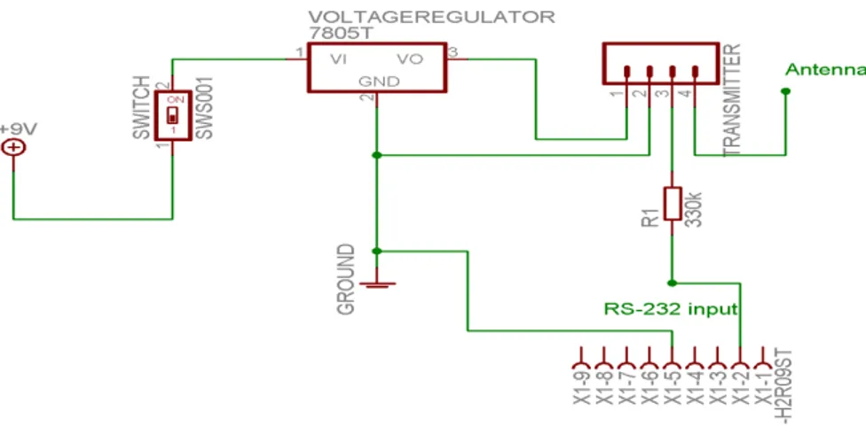
Two types of communication boards designed one is a receiver board, which is placed on each robot, and other is a transmitter board at computer side. Each board required +5V as a supply voltage. The best way to supply exact +5 V to integrated circuits (IC) and TX / RX modules is using a voltage regulator. 7805 IC is used for this purpose at each board. It is 3-terminal positive voltage regulator. It’s operates up to 35 V, output current up to 1 A, and peak current is 2.2 A. Quiescent current is between 5 mA and 8 mA. As shown in below figure of the transmitter schematic circuit is very simple. There are a DB-9 connector, a 7805 voltage regulator, an on-off switch, and a 4-pin TWS-434 transmitter module on the circuit. It is easy to build this circuit, so it is soldered on a printed wiring board (PWB).
Figure 4.7: Schematic of Transmitter Circuit
The first tests with transmitter module are between PC and PIC, and between PIC-to-PIC. These circuits are set up on a breadboard. Data are sending using Hyper Terminal by Windows ® to RS-232 port. Cable is directly connected to PIC. These tests are trying a communication via RS-232 protocol. With another computer it is checked what are received. After it is decided with all success, it is tried with the wireless modules. There is not much information how data are sending and receiving on the net. There are many usage areas with little information about how to use. Transmitter board send data as ASCII codes and it is expected to receive it precisely. In short range it has a high accuracy. However, when the circuit on the breadboard is taken little away, it receives no data. After many tries, the problem is found. It did not work with a power adapter connected, but battery. This was good news, because the project will work wireless module on the robot energized by battery in real-time. Data is now received
24
approximately from 30 meters indoors with a battery supplied receiver circuit with a very high accuracy. Another problem with the wireless modules is that these modules are easy to use and also widely used as remote controllers, and car remote locks. So, if another module used nearby, they cancel each other’s signal, so none are worked. This is an easy predictable problem, to solve, just being careful about not using same module nearby.
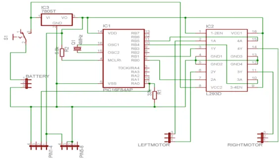
In the figure below, wireless module, PIC microcontroller, motor driver, and voltage regulator are shown as schematic. The connections between each other are also shown. Pins from 1 to 8 are connections to receiver module. The pins are described in Figure 4.5.
Figure 4.8: Schematic of Circuit on the Robot
4.3.2 PIC Programming
PICs can be programmed by many programming languages. PIC assembly, PicBasic Pro (PBP), and MicroC are most popular among them. PicBasic Pro is the most simple and easy to write. In the project the code on the PIC is written by PicBasic Pro. Because the code is not complicate and Basic is quicker and easier to read and write. The code written in MPLAB® IDE implement by Microchip®.
25
PIC microcontroller is just a bridge between receiver and motor driver. It receives data and decides motor driver’s pin levels. The algorithm on the PIC could be listed like this:
a. Initialize ports
i. Choose zero bit of Port A as input
ii. Choose 1st, 2nd, 4th, and 5th bits of Port B as output b. Initialize serial communication specs
i. Baud rate: 2400 ii. Data length: 8 bit iii. Stop bit: yes, 1 bit iv. Parity: no
c. Receive 8-bit data and save it d. Receive another 8-bit data
e. First data represents robot Id. It has to be either 1 or 2. Second data will never save otherwise.
f. Second data represents order for next move. Search in Look-up table.
If the order found in look-up table PIC sends 4-bit signal to motor driver IC, 2-bits for each motor. The truth table of these bits can be found on Error! Reference source not
ound.Table 4.3
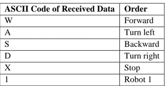
Table 4.2: Look-up Table for Orders ASCII Code of Received Data Order
W Forward A Turn left S Backward D Turn right X Stop 1 Robot 1
26
2 Robot 2
4.3.3 Motor Control
Motors are components, which are converts electric energy to mechanical energy. They are categorized as DC and AC motors. DC motors are easy to use and widely used in robotics applications. The simple DC motor’s principle is depend on passing electric current from a inductor placed inside a permanent magnet’s N and S poles, which provides a rotational motion.
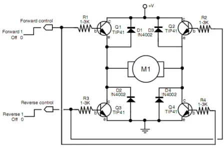
In this work, each robot has two DC motors, each placed on left and right side. To locomotive the robot each has to rotate both clockwise and counter-clockwise. To drive a DC motor in both directions a special designed circuit is needed. H-bridge circuits are used for this purpose. They also give permission to control motors speed with Pulse Width Modulation (PWM). H- Bridge named because the circuit looks like letter H. An example H-Bridge circuit is given at below figure.
Figure 4.9: H-Bridge Circuit
The circuit uses 4 NPN transistors as switch. The diodes are putted to protect possible current overflow, which could be produced in motors bindings, and short circuit possibility if one of the transistor damaged. MOSFETs, or relays can also use for the switches. If the motors do not need much current it is not needed to realize this circuit. There are many built-in H-Bridge ICs in stores. L293x, L297x, L298x families are some
27
of these ICs. In the project L293D is used to drive motors. It is push-pull four channel driver with diodes. The letter D symbolize internal clamp diodes are included.
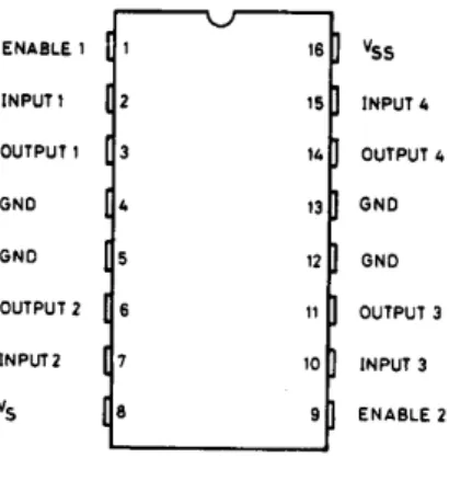
Figure 4.10: L293D Pin Connections
This IC provides 600 mA output current per channel, and 1.2 A peak current per channel. It has over temperature protection and logical “0” input voltage is up to 1.5 V, which means high noise immunity. This IC drive up to 36 V motors, which is also, connected external. Its truth table is given at below figure.
Table 4.3: H-Bridge Truth Table Input 1 Input 2 Function Description
0 0 Off Motor is disabled (coast)
0 1 Backward Turning opposite
1 0 Forward Turning
1 1 Brake Motor is shorted (fast stop)
4.3.4 Electronic Assembly
Finally an electronic circuit, that interfaces wireless communications to robot’s movements, was designed and made. The circuit’s schematic shown in Error!
Reference source not found. and transferred into printed circuit board (PCB)
28
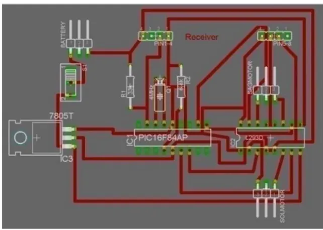
Figure 4.11: Printed Circuit Board of Circuit on the Robot
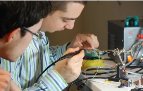
This schematic printed and tried onto a copper plate. First the schematic with only nets shown in red and pads of IC pins shown in green in above figure are printed. They printed to a special blue sheet called PnP transfer paper. Then this paper ironed on a clean copper plate approximately 5 minutes. After ironing, if the image on the paper fully transferred to copper, it should be etching. Ferro III Chloride is used for etching. If it is done properly, it is easy to follow lines, debug circuit, and its size is small and appearance become nice. Although, it seems very easy process, it has some disadvantages. If the something goes wrong while ironing or etching, you have to start all processes from the beginning with a new PnP paper and copper plate. During the preparation of the circuits, there are so many mistakes, problems are occurred. The method become inefficient, and has many misdirected wires. So, the circuits are made by hand on a printed wiring board (PWB), which is a pre-holed copper plate. Soldering and connection all of the connection lines are too difficult and bothering. Also, debugging becomes more painful.
29
Figure 4.12: Soldering Circuits of Robots
After making all electronic process, the results obtained by trial and error in the tests were compared to the results derived by calculations. For example, in the robots a battery with 1800 mAh is used. Total peak power dissipation by the receiver board is can be calculated like this:
Table 4.4: Total Peak Power Dissipation by the Receiver Board
Device Power Dissipation (mW)
PIC Microcontroller (PIC16F84A) 800 mW Motor Driver (L293D) 120 mW (without motor) 1 W (with motors connected) Receiver Module 45 mW
Voltage Regulator (7805)
40 mW
Total 1105 mW (standby)
1885 mW (motors are active)
As seen in the above table, robots could work continuously approximately for 1 hour. Each robot could wait at standby mode less than 2 hours. Beside this, it takes 10 hours to re-charge batteries.
Second robot made by following same procedures. After making two friend robots, the foe sumo robot is made by the same steps excluding circuit. In the foe robot, HandyBoard is used as a control unit instead of PIC microcontroller. A distance sensor,
30
sharp GP12D150, also connected HandyBoard to search moving objects in a constant range. Two light sensors, CNY70, are also connected to detect white borders.
31
5.
SOFTWARE ALGORITHMS
Different software that are used to build this work will explained briefly in further part of this chapter, before describing the algorithms used in this work. Different types of software are used in the progress of the project. Microsoft Visual Studio 6.0 was the main tool to program. OpenCV library is added to take advantage of its image processing functions. On robot control, to program PIC microcontroller PIC Basic Pro is used in MPLAB IDE.
The followed methods to realize the Team Sumo and implemented solutions to the problems occurred are also explained in detail.
5.1 OPENCV
OpenCV is an open source computer vision library originally developed by Intel. It is
free for commercial and research use under a BSD license. The library is cross-platform, and runs on Mac OS X, Windows and Linux. It focuses mainly towards
real-time image processing, as such, if it finds Intel's Integrated Performance Primitives
(IPP) on the system, it will use these commercial optimized routines to accelerate itself (http://en.wikipedia.org/wiki/OpenCV May 20, 2008).
This library is mainly aimed at real-time computer vision. Some example areas would be Human-Computer Interaction (HCI); Object Identification, Segmentation and Recognition; Face Recognition; Gesture Recognition; Motion Tracking, Ego Motion, Motion Understanding; Structure From Motion (SFM); and Mobile Robotics. In short, it is an open source computer vision library in C/C++ and optimized and intended for real-time applications.
In Appendix – IIA it is able to see other properties of OpenCV and how it could be installed into MS Visual Studio 6.0.
5.2 PIC BASICPRO
PIC BasicPro (PBP) is a programming language, which is one of easiest programming language for PICs. It has only 64 instructions. It can be written in any text editor. But it
32
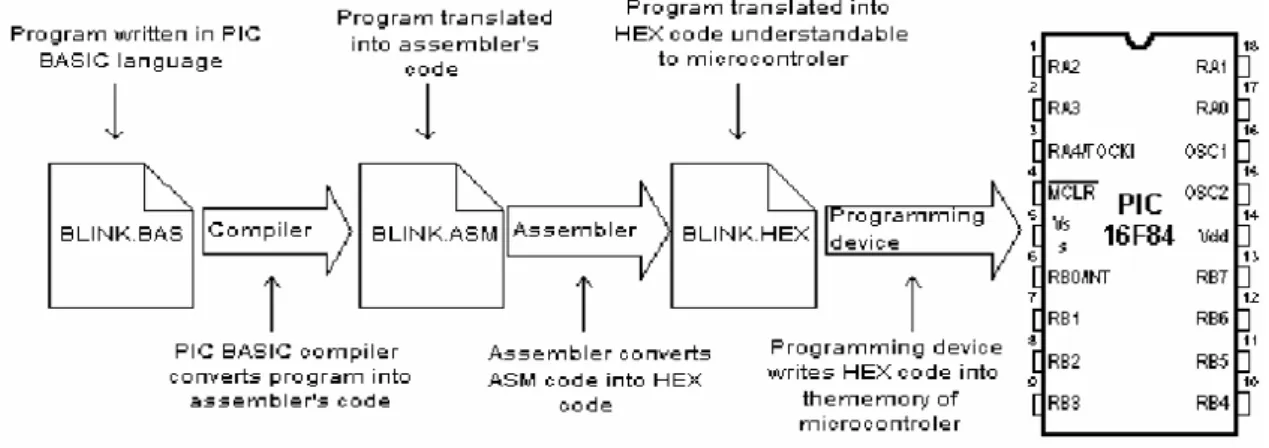
needs a compiler and an upload program to load machine code to PIC inside. After adding PIC BasicPro compiler to MPLAB IDE, it becomes more easy and useful.
Figure 5.13: PIC Programming Overview
In Appendix 2 – A.2, the steps of installing PBP inside MPLAB and creating a basic project in the MPLAB is described.
5.3
ALGORITHMSIn this work, the real problem is finding and tracking objects. Color identification, blob analyzing, threshold segmentation, image segmentation, pattern recognition are the algorithms could be used. If it is a necessarily to use color images, color identification could be the easiest way, as in the beginning of this project.
Other solution to this problem is putting IR LEDs to friend robots instead of colors. Each friend robot must have a unique pattern on it, which used for identify robots and their directions. Although this is a nice solution, webcams used in the project are not enough to detect IR. So, filtering IR and using pattern recognitions algorithms are useless.
Even though color identification is the easiest one, it has so many difficulties itself. The biggest problem is, considering the color space to work on, because different color spaces cause different results. In the project medium, light sources were fluorescent lamps and they were lighting the area from different angles and they flickers. This means, the brightness values are varying in the area, so the color values. This is a big problem.