M.Sc. THESIS
JUNE 2016
GROUP EFFECT IN AXIALLY LOADED CHEMICAL ANCHORS EMBEDDED IN LOW STRENGTH CONCRETE
Thesis Advisor: Assoc. Prof. Dr. Salih YILMAZ
İZMİR KATİP ÇELEBI UNIVERSITY GRADUATE SCHOOL OF NATURAL AND APPLIED SCIENCES
Tolga ARSLAN
İZMİR KATİP ÇELEBİ UNIVERSITY GRADUATE SCHOOL OF NATURAL AND APPLIED SCIENCES
JUNE 2016
GROUP EFFECT IN AXIALLY LOADED CHEMICAL ANCHORS EMBEDDED IN LOW STRENGTH CONCRETE
M.Sc. THESIS Tolga ARSLAN
(130104020)
Department of Civil Engineering
HAZİRAN 2016
İZMİR KÂTİP ÇELEBİ ÜNİVERSİTESİ FEN BİLİMLERİ ENSTİTÜSÜ
DÜŞÜK DAYANIMLI BETONLARA EKİLEN ÇEKMEYE MARUZ KİMYASAL ANKRAJLARDA GRUP ETKİSİ
YÜKSEK LİSANS TEZİ Tolga ARSLAN
(130201016)
İnşaat Mühendisliği Ana Bilim Dalı
v
Asst. Prof. Dr. Mutlu SEÇER ... İzmir Katip Çelebi University
Thesis Advisor : Assoc. Prof. Dr. Salih YILMAZ ... İzmir Katip Çelebi University
Jury Members : Asst. Prof. Dr. Özlem ÇALIŞKAN ... Bilecik Şeyh Edebali University
Tolga Arslan, a M.Sc. student of IKCU Graduate School of Natural and Applied Sciences, successfully defended the thesis entitled “GROUP EFFECT IN AXIALLY LOADED CHEMICAL ANCHORS EMBEDDED IN LOW STRENGTH CONCRETE”, which he prepared after fulfilling the requirements specified in the associated legislations, before the jury whose signatures are below.
Date of Submission : 15 June 2016
vii
ix FOREWORD
I would like to thank the following people who helped me to build this study. I would like to thank my wife and my parents for their continuous support and trust in every area of my life. Thanks for always being there for me, believing in me, and motivating me to set out on my own path
I am also thankful my supervisor Salih Yılmaz for his guidance and being a source aspiration.
Lastly, I would like to thank my great friends and technicians in our laboratory for technical and motivational contributions for this thesis project.
This thesis study was funded by İzmir Kâtip Çelebi University, Scientific Research Projects Coordination Office with Project No: 2013-2-FMBP-36.
June 2016 Tolga ARSLAN (Civil Engineer)
xi TABLE OF CONTENTS Page FOREWORD ... ix TABLE OF CONTENTS ... xi ABBREVIATIONS ... xiii LIST OF SYMBOLS ... xv
LIST OF TABLES ... xvii
LIST OF FIGURES ... xix
SUMMARY ... xxiii ÖZET ... xxv 1. INTRODUCTION ... 1 1.1 Topic ... 1 1.2 Aim ... 3 1.3 Scope ... 4 1.4 Behavior of Anchors ... 5
1.4.1 Cast-in place anchors ... 6
1.4.2 Post-installed anchors ... 6
2. PREVIOUS STUDIES ... 9
2.1 Researches Done for Anchors ... 9
2.2 Literature Evaluation ... 17
3. MATERIALS AND METHODS ... 19
3.1 Experimental Details ... 19
3.2 Material Properties ... 22
3.2.1Concrete ... 22
3.2.2Anchor bars ... 23
3.2.3Chemical adhesive ... 24
3.3 Denotation and Layout of Test Specimens ... 25
3.3.1Denotation of test specimens ... 25
3.3.2Layout of test specimens ... 26
4. TEST RESULTS... 31
4.1 Tests of 12 mm Diameter Anchors ... 31
4.2 Tests of 20 mm Diameter Anchors ... 37
4.2.1 Tests of 20 mm diameter group anchors ... 37
4.2.2 Tests of 20 mm diameter single anchors ... 44
4.3. Calculation of Anchors Capacity According to ACI318 ... 50
4.3.1 Steel strength of anhor in tension ... 51
4.3.2 Concrete breakout strength of anchor in tension ... 51
4.3.3 Bond strength of anchor in tension ... 52
4.3.4 Comparison of ACI strength results and test results ... 53
4.3.5 Comparison of projected failure area per ACI318 values and tests ... 57
4.4. Evaluation of Test Results ... 72
4.4.1 Evaluation of test results for 12 mm group anchors ... 72
4.4.2 Evaluation of test results for 20 mm group anchors ... 74
xii
5. CONCLUSION ... 79 REFERENCES ... 81 CURRICULUM VITAE ... 85
xiii ABBREVIATIONS
ACI : American Concrete Institute
PCI : Precast and Prestressed Concrete Institute CCD : Concrete Capacity Design
TEC : Turkish Earthquake Code
xv LIST OF SYMBOLS
da: nominal outside diameter of post-installed anchor
do: nominal outside diameter of drilled hole in concrete
hef: effective embedment depth, measured from the concrete surface to the deepest point at which bond to the concrete is established
h: thickness of test member in which an anchor is installed, measured perpendicular to the concrete surface
Δh: concrete thickness beyond hef
Ase,N: effective cross-sectional area of an anchor in tension
Futa: specified tensile strength of anchor steel (smaller of 1.9 Fya or 860 MPa) Fya: specified yield strength of anchor steel
ANc: projected failure area
ANco: projected concrete failure area of a single anchor with an edge distance equal
to or greater than 1.5 hef hef: effective embedment depth
Ψec,N: the modification factor for anchor groups loaded eccentrically in tension Ψed,N: the modification factor for edge effects for single anchors or anchor groups
loaded in tension
Ψc,N: the modification factor for anchors based on presence or absence of cracks in
concrete in tension
Ψcp,N: the modification factor for post-installed anchors designed for uncracked
concrete without supplementary reinforcement to control splitting
Nb: the basic concrete breakout strength of a single anchor in tension in cracked concrete
Ana: projected influence area of a single adhesive anchor or group of adhesive anchors
Anao: projected influence area of a single adhesive anchor with an edge distance equal
to or greater than Cna
Cna: projected distance from center of an anchor shaft on one side of the anchor
required to develop the full bond strength of a single adhesive anchor
Ψec,Ns: the modification factor for adhesive anchor groups loaded eccentrically in
tension
Ψed,Na: the modification factor for edge effects for single adhesive anchors or adhesive
anchor groups loaded in tension
Ψcp,Na: the modification factor for adhesive anchors designed for uncracked concrete
without supplementary reinforcement to control splitting
Nba: the basic concrete breakout strength of a single adhesive anchor in tension in cracked concrete
Fctd: characteristic tensile strength of concrete As: cross-section area of steel bar
xvii LIST OF TABLES
Page
Table 3.1 : Mechanical properties of anchor bars. ... 23
Table 3.2 : Mechanical and physical properties of used epoxy [49]. ... 24
Table 3.3 : Test results of epoxy ... 25
Table 4.1 : Test results for S420a 12 mm group anchors. ... 32
Table 4.2 : Test results for S420b 20 mm group anchors. ... 38
Table 4.3 : Test results for S420a 20 mm single anchors. ... 44
Table 4.4 : Strength reduction factors for post-installed anchors [46]. ... 51
Table 4.5 : Comparison ACI318 strength values and test results for S420b anchors 54 Table 4.6 : Comparison ACI318 strength values and test results for S420a anchors 55 Table 4.7 : Comparison between rupture areas of group anchors calculated according to ACI318 and calculated after tests. ... 57
Table 4.8 : Comparison between rupture areas of single anchors calculated according to ACI318 and calculated after tests. ... 58
xix LIST OF FIGURES
Page
Figure 1.1 : Anchors in jacketing of column [4]. ... 1
Figure 1.2 : Anchors connecting infill shear wall to frame. ... 2
Figure 1.3 : Anchors functioning as crossties. ... 2
Figure 1.4 : Anchors in external shear wall application [4]. ... 3
Figure 1.5 : Cast-in place anchors [11]. ... 5
Figure 1.6 : Post-installed anchors [11]. ... 6
Figure 1.7 : Adhesive Anchor [13] ... 7
Figure 1.8 : Anchor failure modes under tensile loading [14]. ... 8
Figure 1.9 : Loading types of anchors. ... 8
Figure 3.1 : 3D view of test setup. ... 19
Figure 3.2 : Test setup. ... 20
Figure 3.3 : Geometrical view of anchors elements. ... 20
Figure 3.4 : Preparation of epoxy. ... 21
Figure 3.5 : Embedment of anchors. ... 21
Figure 3.6 : Mold prepared for pouring of concrete ... 22
Figure 3.7 : Compressive strength test for concrete sample. ... 22
Figure 3.8 : Tensile test of anchor bars. ... 23
Figure 3.9 : Epoxy used for tests... 24
Figure 3.10 : Flexure strength test of epoxy. ... 25
Figure 3.11 : Compressive strength test of epoxy. ... 25
Figure 3.12 : Schematic view of anchors in concrete block B1. ... 27
Figure 3.13 : Schematic view of anchors in concrete block B2. ... 27
Figure 3.14 : Schematic view of anchors in concrete block B3. ... 28
Figure 3.15 : Schematic view of anchors in concrete block B4. ... 28
Figure 3.16 : Schematic view of anchors in concrete block A1. ... 29
Figure 3.17 : Schematic view of anchors in concrete block A2. ... 29
Figure 4.1 : Load (kN) – Time (s) graphic for 12 mm S420a anchors with 18 cm embedment depth. ... 32
Figure 4.2 : Load (kN) – Time (s) graphic for 12 mm S420a anchors with 12 cm embedment depth. ... 33
Figure 4.3 : Test images for Specimen 1. ... 33
Figure 4.4 : Test images for Specimen 2. ... 33
Figure 4.5 : Test images for Specimen 3. ... 34
Figure 4.6 : Test images for Specimen 4. ... 34
Figure 4.7 : Test images for Specimen 5. ... 34
Figure 4.8 : Test images for Specimen 6. ... 35
Figure 4.9 : Test images for Specimen 7. ... 35
Figure 4.10 : Test images for Specimen 8. ... 35
Figure 4.11 : Test images for Specimen 9. ... 36
Figure 4.12 : Test images for Specimen 10. ... 36
Figure 4.13 : Test images for Specimen 11. ... 36
xx
Figure 4.15 : Load (kN) – Time (s) graphic for 20 mm S420b group anchors
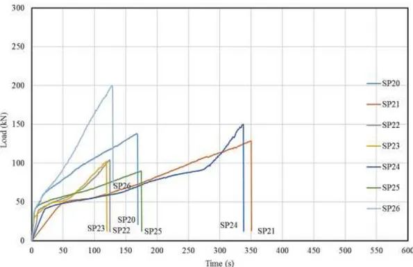
embedded in concrete group B. ... 38 Figure 4.16 : Load (kN) – Time (s) graphic for 20 mm S420b group anchors
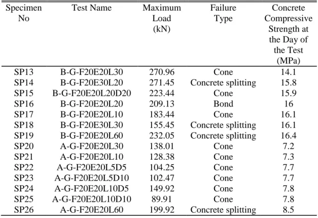
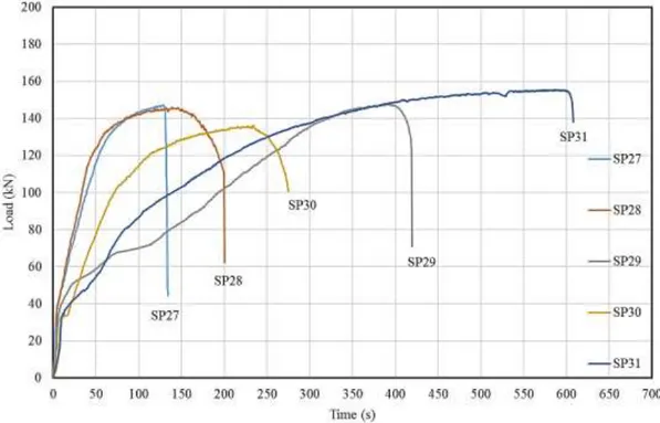
embedded in concrete group A. ... 39 Figure 4.17 : Test images for Specimen 13. ... 39 Figure 4.18 : Test images for Specimen 14. ... 39 Figure 4.19 : Test images for Specimen 15. ... 40 Figure 4.20 : Test images for Specimen 16. ... 40 Figure 4.21 : Test images for Specimen 17. ... 40 Figure 4.22 : Test images for Specimen 18. ... 41 Figure 4.23 : Test images for Specimen 19. ... 41 Figure 4.24 : Test images for Specimen 20. ... 41 Figure 4.25 : Test images for Specimen 21. ... 42 Figure 4.26 : Test images for Specimen 22. ... 42 Figure 4.27 : Test images for Specimen 23. ... 42 Figure 4.28 : Test images for Specimen 24. ... 43 Figure 4.29 : Test images for Specimen 25. ... 43 Figure 4.30 : Test images for Specimen 26. ... 43 Figure 4.31 : Load (kN) – Time (s) graphic for 20 mm S420b single anchors 30 cm
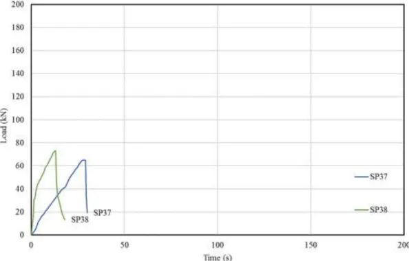
embedded in concrete group B. ... 45 Figure 4.32 : Load (kN) – Time (s) graphic for 20 mm S420b single anchors 20 cm
embedded in concrete group B. ... 45 Figure 4.33 : Load (kN) – Time (s) graphic for 20 mm S420b single anchors 10 cm
embedded in concrete group B. ... 46 Figure 4.34 : Load (kN) – Time (s) graphic for 20 mm S420b single anchors
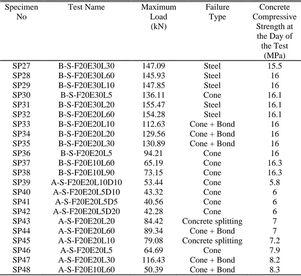
embedded in concrete group A. ... 46 Figure 4.35 : Test images for Specimen 27 to 32. ... 47 Figure 4.36 : Test images for Specimen 33 to 38. ... 48 Figure 4.37 : Test images for Specimen 39 to 44. ... 49 Figure 4.38 : Test images for Specimen 45 to 48. ... 50 Figure 4.39 : Calculation of ANc and ANco for single and group anchors [46]. ... 52
Figure 4.40 : Calculation of ANa and ANao [46]. ... 53 Figure 4.41 : Comparison between maximum test load and ACI318 capacity
strength of 12 mm S420a group anchors. ... 55 Figure 4.42 : Comparison between maximum test load and ACI318 capacity
strength of 20 mm S420b group anchors. ... 56 Figure 4.43 : Comparison between maximum test load and ACI318 capacity
strength of 12 mm S420b single anchors. ... 56 Figure 4.44 : Comparison between maximum test load and ACI design strength of
all tests. ... 57 Figure 4.45 : Rupture area for SP30. ... 58 Figure 4.46 : Rupture area for SP33. ... 59 Figure 4.47 : Rupture area for SP34. ... 59 Figure 4.48 : Rupture area for SP35. ... 59 Figure 4.49 : Rupture area for SP36. ... 60 Figure 4.50 : Rupture area for SP37. ... 60 Figure 4.51 : Rupture area for SP38. ... 60 Figure 4.52 : Rupture area for SP39. ... 61 Figure 4.53 : Rupture area for SP40. ... 61 Figure 4.54 : Rupture area for SP41. ... 61
xxi
Figure 4.55 : Rupture area for SP42. ... 62 Figure 4.56 : Rupture area for SP44. ... 62 Figure 4.57 : Rupture area for SP46. ... 62 Figure 4.58 : Rupture area for SP47. ... 63 Figure 4.59 : Rupture area for SP48. ... 63 Figure 4.60 : Rupture area for SP5. ... 64 Figure 4.61 : Rupture area for SP6. ... 64 Figure 4.62 : Rupture area for SP8. ... 65 Figure 4.63 : Rupture area for SP9. ... 65 Figure 4.64 : Rupture area for SP10. ... 66 Figure 4.65 : Rupture area for SP11. ... 66 Figure 4.66 : Rupture area for SP12. ... 67 Figure 4.67 : Rupture area for SP13. ... 67 Figure 4.68 : Rupture area for SP15. ... 68 Figure 4.69 : Rupture area for SP17. ... 68 Figure 4.70 : Rupture area for SP20. ... 69 Figure 4.71 : Rupture area for SP21. ... 69 Figure 4.72 : Rupture area for SP22. ... 70 Figure 4.73 : Rupture area for SP23. ... 70 Figure 4.74 : Rupture area for SP24. ... 71 Figure 4.75 : Rupture area for SP25. ... 71 Figure 4.76 : Relationship between rupture areas from the tests of 12 mm group
anchors and modified rupture area according to ACI. ... 72 Figure 4.77 : Stress ratios for 12 mm group anchors with cone failure. ... 73 Figure 4.78 : Relationship between maximum loads and rupture area according of 12
mm group anchors. ... 73 Figure 4.79 : Relationship between embedment depth and ultimate stress levels for
12 mm anchors. ... 74 Figure 4.80 : Relationship between edge distance and ultimate stress levels for 12
mm anchors. ... 74 Figure 4.81 : Relationship between rupture areas from the tests of 20 mm group
anchors and modified rupture area according to ACI. ... 75 Figure 4.82 : Stress ratios for 20 mm group anchors with cone failure. ... 75 Figure 4.83 : Relationship between embedment depth and ultimate stress levels for
20 mm group anchors. ... 76 Figure 4.84 : Relationship between edge distance and ultimate stress levels for 20
mm group anchors. ... 76 Figure 4.85 : Relationship between embedment depth and ultimate stress levels for
20 mm single anchors. ... 77 Figure 4.86 : Relationship between edge distance and ultimate stress levels for 20
xxiii
GROUP EFFECT IN AXIALLY LOADED CHEMICAL ANCHORS EMBEDDED IN LOW STRENGTH CONCRETE
SUMMARY
The use of chemical anchors for the connection of existing structural elements with the new elements during strengthening of existing structures is quite a preferred method. Since in our country, chemical anchors are being widely used for repair and strengthening works, there should be a standard of design and application on this topic. Up to now, research done on the topic of chemical anchors, are mostly carried out on concrete blocks of compressive strength 20 MPa and higher. Since parameters such as distance from the edges, embedment depth and group effect were mostly ignored, the resulting behavior was brittle, instead of the desired ductile behavior. This is particularly true for low strength concretes, in which concrete related damages increase the probability of an overall brittle behavior.
In the scope of this study, 100 epoxy bonded anchors were embedded into concrete blocks of strength between 5.8-16.4 MPa. Among these anchors, 22 were single anchors, and 26 were group of three anchors. In these experiments, 12 mm S420a and 20 mm S420b rebars were used. The behavior of the anchors was investigated by varying embedment depth and distance from edges and corners.
It was observed that stress concentrations in projected failure area are more significant for greater bar diameters. And increase in expected stress levels, increases the possibility of having concrete governing failure. Therefore, it is suggested to put an upper limit in codes for bar diameters.
It was observed that stress concentrations in projected failure area are more significant for greater bar diameters. And increase in stress levels, increases the possibility of having brittle concrete breakout failure. Therefore, it is suggested to put an upper limit for bar diameter to limit this possibility. Besides, findings about stress concentrations show that ACI318 formulation yields safer design strength for small-diameter anchors with respect to large-diameter anchors. To compensate this, some modification factors have been proposed for the calculation of projected breakout failure area according to ACI318.
Calculated design strengths of specimens per ACI318 were lower than anchor capacities obtained from tests. It is observed that average factor of safety for majority of the experiments is around 2. Therefore, it is concluded that ACI318 design strength can safely be used for most of the anchor configurations. However, in some experiments, ultimate capacity of specimens were very close to ACI318 design strength. This is especially observed for the cases where stress concentrations occur, for example group anchors with large diameter bars located parallel to edges.
xxv
DÜŞÜK DAYANIMLI BETONLARA EKİLEN ÇEKMEYE MARUZ KİMYASAL ANKRAJLARDA GRUP ETKİSİ
ÖZET
Mevcut betonarme yapıların onarım ve güçlendirme işlemlerinde, mevcut beton ile yeni yapısal elemanların beraber çalışması için kimyasal ankrajların kullanılması sıklıkla tercih edilen bir yöntemdir. Ülkemizde onarım ve güçlendirme işlemlerinde sıklıkla kullanılan kimyasal ankrajlarla ilgili ülkemizde özel bir tasarım uygulama standardı bulunmamaktadır. Bu konuyla ilgili daha önce yapılan çalışmalar da genellikle 20 MPa ve üstü basınç dayanımına sahip betonlarda yapılmıştır. Sisteme sonradan eklenen bu tip ankrajların kenar mesafesi, gömülme derinliği ve grup etkisi gibi sebeplerin göz ardı edilmesi sonucu istenen sünek davranış yerine gevrek bir davranış göstermesi olasıdır. Özellikle düşük dayanımlı betonlarda, betona bağlı hasarların oluşarak gevrek davranışın görülme olasılığı artmaktadır.
Çalışma kapsamında 5.8-16.4 MPa arası basınç dayanımına sahip beton bloklara toplam 100 adet epoksi ankraj ekilmiştir. 26 adet üçlü grup ankraj, 22 adet ise tekil ankraj çekme deneyine tabi tutulmuştur. Deneylerde S420a, 12 mm ve S420b, 20 mm donatılar kullanılmıştır. Deneylerde gömülme derinliği, kenar ve köşe mesafeleri değiştirilerek, ankrajların farklı koşullar altındaki davranışları incelenmiştir.
Gerilme yığılmasının, öngörülen göçme alanında büyük donatı çapları için daha önemli olduğu görülmüştür. Beklenen gerilme seviyelerindeki artış, beton kaynaklı gevrek göçme ihtimalini de arttırmaktadır. Bu nedenle, donatı çapları için bir üst limit koyulması tavsiye edilmektedir. Bunun yanında, gerilme yığılması ile ilgili bulgular ACI318 formülünün küçük çaplı ankrajlarda büyük çaplı ankrajlara göre daha güvenli tasarım dayanımı verdiği görülmektedir. Bunu gidermek amacıyla, ACI318’e göre öngörülen göçme alanı hesabı için bazı düzeltme faktörleri önerilmiştir.
ACI318’e göre hesaplanan numune tasarım dayanımları, deneylerden elde edilen ankraj kapasitelerinden daha küçük değerlerdir. Deneylerin çoğunda elde edilen ortalama güvenlik faktörünün 2 civarında olduğu görülmektedir. Bu nedenle, ACI318 tasarım dayanımlarının çoğu ankraj düzeninde güvenli biçimde kullanılabileceği sonucuna varılmıştır. Ancak bazı deneylerde, numunelerin nihai kapasitesinin ACI318 tasarım dayanımına çok yakın değerler verdiği görülmüştür. Bu durum, özellikle büyük çaplı grup ankrajların kenarlara paralel olduğu gibi gerilme yığılması meydana gelen durumlarda gözlenmiştir.
1 1. INTRODUCTION
1.1. Topic
Most of the existing structures in Turkey do not fulfill regulations stated in Turkish Earthquake Code and strengthening is required for them [1]. Repairing and strengthening of existing reinforced concrete structures with new structural elements like shear walls bonded to existing members with chemical anchors is a widely used technique [2].
Fast, easy and low cost application of chemical anchors has increased the use of this type of anchors. Additionally, chemical anchors can be designed according to different design needs which makes that a big advantage [3].
Anchors are used in repair and strengthening works for jacketing of columns (Figure 1.1), addition of infill shear wall (Figure 1.2), as crossties (Figure 1.3) and external shear wall (Figure 1.4).
2
Figure 1.2 : Anchors connecting infill shear wall to frame.
3
Figure 1.4 : Anchors in external shear wall application [4].
During design of anchors, what type of loading they will be subjected to and behavior under this loading must be taken into consideration. Wrong design or wrong application will result in anchors not to behave as predicted. For this reason, after a proper design, some factors must be taken into consideration also during application of chemical anchors such as: hole of anchors must be kept clean, surface of concrete must be dry, temperature and other environmental factors [5].
1.2. Aim
In Turkey, there is detailed standards or guidelines for design of chemical anchors to be used for repair and strengthening. In Turkish Earthquake Code 2007 [1], there is a chapter for repair and strengthening, but there is no detailed regulations for the use of anchors. In the current strengthening practice, the tensile capacity of anchors used to connect existing and new elements is tested up to 70% of the tensile strength of the
4
steel rebar. There is a considerable doubt about this design practice such that brittle behavior is expected due to low concrete strength [4]. When considering our country’s building stock, brittle behavior should mostly be expected at low strength concrete. Also, anchors located in close vicinity with each other are known to work together as group anchors. It is known that parameters like distance between anchor bars and embedment depth effect brittle behavior [6].
Most of experimental studies existing in literature about tensile behavior of anchors are done on normal strength concrete, corresponding to compressive strength between 20-50 MPa [7-9]. There is a few number of tests for behavior of anchors at concrete with compressive strength of 20 MPa or lower and most of these tests are designed not to allow breakout damage of concrete. However, especially in low strength concrete, it is experimentally showed that brittle concrete damages may appear [4]. Even though, this brittle behavior is more likely to be observed in the case of group anchors, the tests carried out on low strength concrete are mostly single anchor tests.
Investigations done after recent earthquakes in Turkey have shown that average concrete strength varies mostly in the range of 8-15 MPa [10]. Generally, the structures requiring strengthening in Turkey have very low concrete strength, in the range mentioned.
Especially in the case of added infill shear walls, the anchors used to connect the wall with the foundation are very important in terms of ductility. Since these anchors are generally close with each other the effect of grouping should be considered. Due to this fact tensile behavior of chemical anchors at low strength concrete must be investigated.
In the aim of study, tensile tests were done on group anchors at concrete elements with compressive strength of 5.8-16.4 MPa representing most of existing reinforced concrete structures. In order to achieve real behavior, tests were done in a way that group action is allowed. Aim of this study is to investigate behavior and strength of anchors subjected to tensile load.
1.3. Scope
Plain concrete blocks were used for anchoring within the scope of the study. Compressive strength of blocks was between 5.8-16.4 MPa which represent most of
5
the existing structures in Turkey. Dimensions of each concrete blocks were 50cm x 150cm x 250cm. S420a anchor bars with 12 mm diameter and S420b anchor bars with 20 mm diameter were embedded in those concrete blocks. Embedment of anchors were achieved by using epoxy. In all tests, the same type of epoxy was used in order to avoid differences due to materials.
In the tests, group of three anchors were embedded in concrete blocks with a distance form free edges of 5, 10, 15 and 20 times anchors bar diameters and at a depth of 5, 10 and 15 times anchors bars diameter. Tests were conducted in laboratory conditions. Cleaning hole of anchors, moisture content of concrete surface and temperature were not investigated in our study.
1.4. Behavior of Anchors
American Concrete Institute (ACI) has defined anchor as a steel element either cast into concrete or post-installed into a hardened concrete member and used to transmit applied loads to the concrete and anchor group as a number of similar anchors having approximately equal effective embedment depths with spacing between adjacent anchors such that the protected areas overlap [11]. The institute categorizes anchors in two groups according to concrete lay-out as cast-in place anchors (Figure 1.5) and post installed anchors (Figure 1.6). In Figure 1.5, anchors are hex head bolt with washer, L-bolt, J-bolt and welded headed stud, respectively. Anchors in Figure 1.6 are adhesive anchor, undercut anchor, torque-controlled expansion anchor, sleeve-type anchor, stud-type anchor and drop-in type displacement controlled expansion anchor, respectively [11].
6
Figure 1.6 : Post-installed anchors [11]. 1.4.1. Cast-in place anchors
Generally, anchors applied at fresh concrete are used as connective elements for steel and concrete. During design of anchors for fresh concrete in order to achieve ductile behavior load must be transferred to bars before failure of concrete.
1.4.2. Post-installed anchors
Anchors embedded after concrete has gained its strength are divided in two types as bonded anchors and mechanical anchors. Anchors embedded after hardening of concrete, is frequently used for strengthening of structures. They are divided in two types: bonded anchors and mechanical anchors. Bonded anchor is the type of anchors that is embedded in concrete after a hole is opened and empty space between anchor bar and concrete is filled with adhesive material. Mechanical anchor is the type of anchors that is embedded in open hole and friction force between anchor bar and concrete transfers the loads from the bar to concrete. Bonded anchors are further divided into groups according to adhesive material type: polymer based or cement based [12].
Mechanical anchors are divided in two groups: pre-stressed and expansion anchors. This type of anchors is transferred loads to concrete with mechanical friction and interlocking system through anchor depth.
Chemical anchors are mostly used type of anchors for strengthening. This type of anchors is made up of three different elements, anchors bars, concrete block and chemical adhesive. Chemical anchors are transferred loads to concrete with adherence through anchor depth. In chemical anchors, bond between concrete and anchors due to chemical adhesive material makes anchors bar and concrete act together (Figure 1.7).
7
Figure 1.7 : Adhesive Anchor [13]
Polyester, vinylester, epoxy and polyurethane are commonly used adhesives for chemical anchors. Epoxy is mostly used bonding material among the others. In order to have better transfer of load from anchors elements opened hole must be fully filled with adhesive material that has proper consistency. Chemical anchors showed nearly elastic behavior under axial load up to collapse or yield [9]. Chemical adhesives (especially epoxy) are among the best solutions providing the bonding forces between the concrete and steel. Adherence components for chemical anchors are:
Friction between epoxy and concrete Friction between epoxy and steel
Chemical bond between epoxy and concrete Chemical bond between epoxy and steel Mechanical forces on steel [2]
Failure mode of chemical anchors subjected to tensile loading are divided into 5 groups [14]. As seen in Figure 1.8 these are:
Rupture of anchor bar Yielding of anchor bar Concrete cone failure Bond failure
8
Figure 1.8 : Anchor failure modes under tensile loading [14].
Steel is a ductile material, which makes it possible to have ductile RC behavior. Among these, only steel failure may result in good ductility. Therefore, designers should avoid having other types of failures especially in seismic areas.
Figure 1.9 shows type of load under which anchors are subjected as given at ACI 355.2 [15]. These type of loading:
Axial tensile loading Shear loading
Combined tensile and shear loading Flexure loading
9 2. PREVIOUS STUDIES
2.1. Researches Done for Anchors
Peier [7] investigated tensile behavior of chemical and expansion single anchors embedded in concrete with compressive strength of 25-50 MPa. In the research was investigated only the damages of concrete but failure of anchors was not taken in consideration. An analytical model was prepared and results were compared with experimental ones. Results taken form analytical analysis consisted with experimental results. According to plastic model, concrete failure model effected by the connection type, anchors static behavior provided more reliable results. It was seen that anchors under tensile load caused stress failure and capillary cracks in concrete.
James et al. [16] investigated the behavior of embedded anchors with epoxy in hardened concrete using linear and non-linear analysis. In order to indicate the maximum tensile stress, Mohr Coulomb theory and maximum tensile stress theory were applied. Results obtained from analytical models were compared with existing experimental results in literature. It was indicated that obtained results can be a beginning for modeling of anchors embedded with epoxy. In the end of tests were obtained two different conic failures with different angels (60˚ in linear analysis and 45˚ in nonlinear analysis). Also it was indicated that ratio of embedment depth and anchors diameter must be greater than 0.75.
Cook et al. [8] investigated failure type and load displacement characteristic at different type of anchors (cast-in, expansion, mortar and chemical). For tests, 16 mm diameter anchors and concrete with compressive strength of 34.5 MPa were used. Tensile behavior under static load, impact load and large cyclic load was tested. At the end of tests, it was seen that chemical and mortared anchors capacity is related to chemicals used.
Cook et al. [9] conducted an experimental study for developing bond stress model. In the study were used 16 mm screwed anchors and six different type of adhesives. After
10
embedding anchors in blocks with compressive strength of concrete 24.8 MPa, tensile tests were conducted. In the tests, were used fully connected single, half connected single and fully connected double anchors. By using both experimental and analytical conceptions, they suggested “Uniform Bond Model” for elastic behavior of foundation area. In the end of the study, design suggestions for three types of anchors were given. It was seen that half connected anchors, embedded at the same depth with fully connected anchors showed the same capacity.
Cook [17] suggested a rational design in order to determine tensile strength capacity of chemical anchors and to see all failure types. It is suggested that conic failure and debonding are connected with behavior taken form elastic theory. Results of 280 tests were compared for design suggestions of anchors capacity. In the end of the study, tensile behavior of bonded type anchors was divided in three categories such as: short embedment depth, medium embedment depth and long embedment depth. Each of them had a different failure mode. It was indicated that usage of different chemical adhesive materials showed different capacity and deformation characteristics.
Fuchs et al. [6] suggested concrete capacity design (CCD) as a new approach, in the scope of studies done for design of anchors, for anchors embedded in hardened concrete and cast-in place anchors. In the context of the study 1200 tests were investigated and tensile loading and shear loading parameters were taken into consideration. In the end of the study, it was seen that concrete capacity design method provided suitable results for failure load of concrete. It was seen also that some results were matching with results given at ACI 349 [18] but some of them not. Taking into consideration this fact, they suggested usage of concrete capacity design method. Zavliaris et al. [19] made an experimental study related to anchor connected chemically with concrete. They investigated stress-strain graphs caused by maximum load until failure of anchors. In tests, 12 mm diameter anchors were embedded at a depth of 100 mm, in C25 concrete samples. In the end of tests, it was seen that displacement of anchors with same diameter have linear relationship between concrete strength and embedment depth. Also, for tensile load it was seen that relationship between embedment depth and diameter was increased linearly.
Mcvay et al. [20] investigated conic geometry of eighteen samples where chemical anchors were embedded at four different depths 76 mm, 102 mm, 127 mm and 152
11
mm by keeping all other parameters same. For these tests concrete with compressive strength of 24.8 MPa for 28 days was produced and for this concrete cylindrical compressive strength for 90 days changed from 39 to 43.4 MPa. In the end of the study, it was seen that probable failures are near surface and conic concrete failure and failure between connection of concrete and adhesive material started from surface. Also, it was seen that between conic failure and anchors axis was created an angle of 56˚ -65˚. Cook et al. [21] investigated the behavior of chemical anchors under effect of tensile loads at uncracked concrete. In the scope of study were used 888 experimental data taken from tests done in USA and Europe and they were done studies for design of chemical anchors embedded away from free corners. It was defined that “Uniform Bond Model” was the proper model after comparing data of different design models. It was suggested that development for the model for group anchors under the effect of edge distance. It was seen that for some of materials with high adhesive strength and high load transfer with increase of concrete strength anchors performance is increased but for some chemical adhesive anchors, performance is not affected from concrete strength.
Obata et al. [22] investigated experimentally and analytically tensile strength of bonded anchors located to near free corners. In the end of the study, in order to estimate conic failure strength new method was suggested using linear cracking mechanism. Conic failure strength was calculated according to ACI 349 [18]. They worked on uniform stress distribution in the concrete surface failure and cracks created by critical load. It was defined that if anchors are near free corners, cracking behavior of foundations will be different form normal case.
Cook and Konz [23] carried out 765 reference tests with 20 structural chemicals, from twelve different companies. The parameters investigated were the surface cleaning, the average moisture content and saturation. Among the twenty chemicals that were used, fifteen of them showed no difference in bond strength between the specimens whose surfaces were cleaned and those whose surfaces were not cleaned, while one of the chemicals provided the pullout strength to be 46% greater for the specimens whose surface was not cleaned, as compared to the specimens whose surface was cleaned. For the chemical which gave the lowest bond strength, when used on surface that was not cleaned, the ratio of the bond strength of the specimen with surface that was not cleaned with that of the properly cleaned specimen was 0.19.
12
Özkul et al. [12] investigated capacity of anchors embedded in concrete with compressive strength of 14 MPa, 20 MPa and 25 MPa, which is hardened with two different type of epoxy, one layer of mortar and 14, 18 and 22 mm diameter ribbed bars. In the end of study, comparison done according to the diameter of bars.
Gross et al. [24] investigated the behavior of single and double anchors subjected to static and dynamic loading. In the scope of study, the behavior of anchors embedded near corners subjected to static and dynamic loading was investigated as well. In the context of experimental study used variables are concrete type and capacity, presence of concrete cracks and loading speed. In the end of study, it was seen that single and double anchors near corners subject to shear loading showed dynamic behavior. Bickel and Shaikh [25] studied the shear capacity of adhesive anchors by applying Precast/Pre-stressed Concrete Institute (PCI) method and concrete capacity design (CCD) method. In the end of the study, it was seen that shear failure mode of adhesive anchors was similar with mechanic anchors and PCI and CCD method can be both effective ways to predict shear capacity of adhesive anchors.
Fujikake et al. [26] studied behavior of chemical anchors subject to rapid tensile loading. In this study was investigated effect of loading speed to the largest tensile capacity. Anchors were embedded at 40, 65, 70, 90 and 120 mm depth at concrete with compressive strength capacity of 32 MPa. In the end of the study, it was seen that bonding capacity and conic failure strength was increased with loading speed.
Shirvani et al. [27] evaluated four different methods for concrete failure capacity of anchors embedded in cracked and uncracked concrete under effect in static and dynamic loads. A comparison was done between 45˚ conic method, concrete capacity method and theoretical method, to observe capacity of anchors due to damages of concrete. In the end of study, it was noted a lower probability of failure for tensile capacity of anchors, according to concrete capacity method, theoretical method and 45˚ conic method.
Özturan et al. [28] investigated behavior and failure mode of chemical, mortared and expansion mechanical anchors embedded after pouring of concrete subjected to static tensile, repeated tensile and shear loading. In the scope of the study were used plain, fiber reinforced normal and high strength concrete. In the end of the study it was seen that with increasing of concrete capacity, carrying capacity of chemical and mortared
13
anchors was increased with 30% and for expansion anchors it was increased with 20%. Besides, it was noted that with increase in diameter and embedment depth, failure load of anchors was increased.
Gesoğlu et al. [29] applied tensile test on thirty seven chemical bonded and eighteen mortar bonded samples. Chemical bonded anchors with 12 mm and 16 mm bar diameter were embedded at a distance of 40 mm and 160 mm. Mortar bonded anchors with 16 mm bar diameter were embedded at depth 80, 120 and 160 mm. They used steel fiber concrete and reinforced concrete. In the end of the study it was noted that with addition of steel fibers at anchors tensile test an increase in capacity was obtained. It was noted that ACI 349 [18] method gave better results than concrete capacity design method for prediction of anchor capacity for 12 mm and 16 mm bar diameter chemical bonded and mortared anchors embedded at lower depth.
Alqedra and Ashour [30] using neural network model tried to estimate shear capacity of single anchors embedded near corners. They created a model using database made up of 205 tests taking into account variable such as anchor diameter, concrete compressive strength, embedment depth of the anchors and anchor edge distance. Results obtained from the model were shown to be compatible with database experimental results and ones calculated according to concrete capacity design method. In the end of the study, applied shear load effected shear capacity of anchors significantly for the ones with distance from corners of concrete, beside that embedment depth and anchors diameter didn’t effect too much.
Sakla and Ashour [31] tried to predict tensile capacity of single anchors by using artificial neural networks. In the study, seven different design parameters were used as input and bonding capacity of adhesive anchors was taken as output. It was seen that compressive strength of concrete linearly effected tensile capacity of anchors and it is also effected by the type of chemical binder.
Seyhan [32] used five different type of bonding materials in a thesis study. Eighty anchors were embedded in concrete blocks with capacity of 16 MPa and behavior under tensile loads was observed. They investigated effect of bonding materials on anchor hole diameter, embedment depth and behavior of concrete surface. In the end of the study, it was observed that when anchor depth is increased anchors capacity is increased and type of used bonding material is an important factor on anchor behavior.
14
Eligehausen et al. [33] carried out an analytic and experimental study related to design standards of chemical anchors and proposed a behavior model. Experimental data of 415 chemical anchors and 133 chemical anchors embedded close to free edges were compared found in world databases. Chemical anchors were embedded in concrete blocks with capacity of 16 MPa and free edge anchors type were embedded in concrete blocks with capacity of 21.8 MPa and experimental studies were carried out. Used anchors were with diameter between 8-24 mm. It was observed that critical space and critical free edge distance of chemical anchors is not related to embedment depth of anchors but they related to anchors diameter and bond strength.
Kaya [34] carried out tests using 16 mm diameter S420a bars, using same hole diameter, bonding material and 14 MPa concrete compressive strength for strengthening process taking into consideration dimension of applications. Effect of embedment depth and different surface conditions on tensile behavior of full or partially connected anchors was investigated. It was seen that partially connected anchors showed two-times greater failure capacity than fully connected anchors. Mazılıgüney [35] did tensile tests on concrete blocks with capacity of 5-16 MPa. Maximum tensile load was defined for anchors. In the scope of study, effect of concrete compressive strength, anchor hole, diameter and cleanness of anchor hole on tensile behavior of chemical anchors was studied. It was defined that anchor diameter is an important factor on tensile behavior of chemical anchors at low concrete capacity. In a thesis by Gürbüz [2] in order to represent the building stock of Turkey, eighty five anchors were tested for tension, on concrete of compressive strength 12.7 MPa. In this study, different embedment depths, the cleanliness of the anchor hole and the moisture of the surface of concrete block was investigated. Besides, the case when perfect bonding between concrete and steel is present, partial bonding was investigated and presented as an alternative.
Çalışkan [36] carried out an experimental study divided into two parts. In the first part, anchors embedded in low strength concrete were tested under shear loading. In the other part of the study, the effect of increasing the number of anchors connecting external shear wall to reinforced concrete frames was investigated. The results of the study indicate that in case concrete damage should is expected, a different design procedure should be used.
15
Özen [4] made tests over concrete blocks with compressive strength of 5 - 25 MPa. In this study, 337 anchors with bars types S420a and S420b were embedded in concrete blocks and tensile tests were applied. It was observed that when anchors embedded near edge and yielding and tensile capacity are reached concrete behave as ductile. Besides, ACI318 suggests the use of rebars of grade S420a accompanied by big safety factors, while the use of rebars of grade S420b is not suggested.
In another study by Yılmaz et al. based on the available literature on chemical anchors, the factors affecting the capacity of the anchors were investigated [5]. Variables effecting performance of anchors were taken into consideration such as: Bonding material type, cleanness of anchors hole, moisture content, high temperature, free edge distance and space between anchors, effect of short curing time and connective of anchors. It was seen that factor such as bonding material type and cleanness of anchors hole have more effect on capacity of anchors. It was observed that embedment depth and concrete type had a limited effect on capacity.
Barnat et al. [37] evaluated to test results that carried on chemical anchors on literature. Results of experimental and analytical tests for limits on bonding capacity and behavior are examined in the study. Aim of the study was to ascertain a design method defining effects of bonding type and spread connected anchors type at high strength concrete. Results showed that properties of bonding material used at high strength concrete for chemical anchors are important factors.
Özdemir in the scope of the thesis study used two types of beam, in one of them to represent new concrete element and the other one to represent existing concrete element [38]. Concrete with compressive strength of 8 and 20 MPa was used. Anchor bars of S420a with a diameter of 12 and 16 mm were embedded at depth 10Ф and 15Ф and subjected to shear load. Results showed that in order to achieve a high shear load capacity anchors must be used more frequently and embedment depth must be increased. It was suggested that chemical anchors subjected under deflection must be embedded in concrete with compressive strength greater than 12 MPa. In a different part of the same study, Altan [39] used concrete and steel with same properties but investigated tensile behavior of anchors embedded at depth 10Ф and 15Ф. In the end of the study, it was concluded that chemical anchors embedded after hardening to concrete are more effective than mechanical anchors. It was observed that bonding capacity is better at 10Ф depth.
16
Kim et al. [40] investigated tensile and shear capacity, torsion ratio, embedment depth and diameter of anchors embedded in plain concrete. Using (ABAQUS) finite element program analyzed anchor systems. Results showed that load capacity is increased when diameter and embedment depth is increased and it was seen both in tensile and shear tests. Also, it was observed that failure mode between anchors and concrete is related to contact area.
Çalışkan et al. studied on shear strength of epoxy anchors embedded into low strength concrete blocks with compressive strength of 5.9 MPa and 10.9 MPa. In the tests, S420a anchors with diameter 12 mm, 16 mm and 20 mm were used. The depth of holes is 10, 15 and 20 times that of the anchor diameter. In the experiments, anchors have been embedded far away from the free edge so as not to cause any concrete failure. The results derived from the study, indicate that increasing the anchor diameter have decreased the shear strength. Moreover, the anchor damage has been resulted from steel failure, a decrease in shear capacity was observed with the lower strength concrete.
Yılmaz et al. [41] investigated tensile capacity of chemical anchors embedded in concrete blocks with compressive strength of 5.9 MPa and 10.9 MPa. In the tests, S420a anchors with diameter 12 mm, 16 mm and 20 mm where used. Anchors were embedded 10, 15 and 20 times anchors bar diameter and free edge distance were used as test variables. Results showed that at low strength capacity concrete in order to obtain a ductile behavior free edge distance and embedment depth must be at least fifteen times anchors bar diameter.
Contrafatto and Cosenza [42] investigated behavior of chemical anchors embedded after hardening in natural stones. They compare experimental results with analytical analysis. The aim of the study was to find the lowest embedment depth of chemical anchors embedded in basalt, sandstone and limestone using epoxy. In the end of the study it was evaluated that available theoretical formulas for concrete are valid. It was investigated that theoretical formulas weren’t suitable and in order to estimate load carrying capacity of anchors some analytical model can be applied.
Rao and Arora [43] did an experimental study for the performance of chemical anchors and strengthening technics at reinforced concrete systems. They controlled capacity of anchors embedded as stirrups at depth of 150, 200 and 250 mm at concrete with
17
compressive strength of 25, 40 and 60 MPa. In the end of the study it was seen that sudden drop of load carrying capacity of anchors at plain concrete is related with conic failure formed. It was observed that load carrying capacity of anchors was increased when concrete capacity and embedment depth were increased.
Wang et al. [44] investigated tensile behavior of large diameter anchors embedded after hardening in concrete of foundation. The aim of the study was to observe the most suitable bonding load and maximum tensile load. Embedment depth and anchor diameter were chosen as variables. In the end of the study, it was seen that when anchor diameter is increased tensile load is increased as well. It was also observed that together with increase of anchors diameter, failure modes changed towards concrete after failure of anchors. It was observed that grooved bar is more suitable than straight ones.
Epackachi et al. [45] observed behavior of single and group anchors embedded after hardening to concrete subjected to tensile and shear loads. Concrete used for tests had a compressive strength varying from 49-60 MPa. Obtained results were compared with the ones taken from equations given at ACI318 [46]. Comparison of results showed that results obtained from equations given at ACI318 were not consistent with experimental results.
Nilforoush et al. [47] observed behavior of adhesive anchors subjected for a long time to loads. Adhesive anchors were subjected to long-term loading as short-term average maximum capacity of adhesive anchors were 23%, 47% and 70%. In the end of the study, it was observed that for indoor environments anchors subjected to prolonged loading until 47% of short-term average maximum capacity of adhesive anchors showed good behavior. It was observed that indoor deformations are increased due to effect of outside factors (temperature, moisture etc.).
2.2. Literature Evaluation
Having examined the literature about anchors, it was seen that most of studies were based on tensile and shear behavior. Researchers have done experimental studies for anchors, failure mode of anchors and model that can be applicable. In some of these studies analytical solution was done also and results were compared with experimental ones.
18
In existing studies, embedment depth and diameter of anchors was the basic parameters examined. In addition to these variables, anchors behavior was studied under effect of different bonding materials, in cases of fully or partially connected anchors, distance from corners, proper cleaning of hole and different strength capacity concrete.
Most of experimental studies in existing literature for tensile behavior of anchors are for concrete grades having compressive strength of 20-50 MPa. There were few experimental studies for anchor behavior of concrete with compressive strength 20 MPa and lower. It was examined that most of existing reinforced concrete structures have concrete strength at this range. Most of studies done are related to single anchors effect and group anchor effect is not well studied, especially for low strength concrete. It was seen that in most of those studies, concrete breakout damage is now allowed because of loading setup. It was thought that at lower strength concrete brittle failure of concrete may occur. Occurrence of brittle behavior waited to be increased due to effect of group anchor, it was seen also that tensile behavior of single anchor embedded in low strength concrete.
Turkish Earthquake Code [1] includes relevant provisions for anchors. In standards lowest boundary of anchors diameter is suggested as 16 mm and maximum distance between anchors is limited to 400 mm. Besides, embedment depth must be at least ten times bar diameter. For determination of shear capacity of anchors TS500 sliding shear capacity can be used [48]. Both of them do not suggest a calculation method for anchors tensile capacity. Engineers usually design anchors, assuming that properly placed anchors will behave in a ductile manner, and instead of observing damage in concrete, steel yielding should be reached first.
However, this assumption is completely baseless. In some studies, for anchors with nearer edge distance and shallow single anchors bar capacity was unreached. In strengthening design, proper design of anchors provided a ductile behavior. It is thought that especially in low strength concrete, brittle failure is more probable in case of group anchor behavior.
In this study, as majority of existing structures have low strength concrete, concretes with compressive strength of 5.8-16.4 MPa were used and group effect has been studied, which will be expected to be a major contribution to existing literature.
19 3. MATERIALS AND METHODS
3.1. Experimental Details
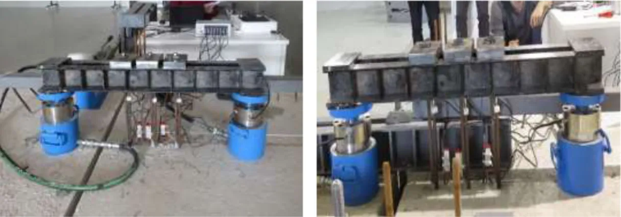
Six concrete blocks with 5.8-16.4 MPa compressive strength were used casted in this research. Each of plain concrete blocks has 50cm x 150cm x 250cm dimensions. S420a anchor bars with 12 mm diameter and S420b anchor bars with 20 mm diameter were embedded in concrete blocks by using epoxy. In each tests, the same type of epoxy was used. During the test in order to measure load applied to specimens two load cells and to measure displacement six displacement transducers were used. Data collected from load cells and displacement transducers were record with a data acquisition system. In tests, in order to allow breakout type of anchors failure and to collect displacement values easier two U profile steel beams connected with each other were used as a loading beam. During the test, concrete blocks were connected to rigid slab and one other concrete block was used as a support for loading beam (Figure 3.1-2).
20
Figure 3.2 : Test setup.
In each test, anchors were placed in group of three with a distance 5Ф, 10Ф, 15Ф and 20Ф from sides and they were embedded at a depth of 5Ф, 10Ф and 15Ф (Figure 3.3). Anchor groups were embedded either parallel or perpendicular to sides. The diameter of holes opened to embed the anchors were 4 mm more than the diameter of anchors. Anchor bars were embedded perpendicular to the surface of concrete blocks. Tests were done in İzmir Kâtip Çelebi University Structural Mechanics Laboratory in the same conditions and environmental parameters such as moisture of concrete block surface, cleaning of hole of anchors, general temperature were not taken into consideration.
21
Firstly, before embedment of anchors, holes with diameter 4 mm more than that of anchor bars were open (16 mm and 24 mm). After that, opened holes were cleaned with an oil-free air compressor. This step was repeated until no dust were left in holes. Secondly, epoxy was prepared according to application sheet given as seen in Figure 3.4. During application of epoxy to holes it was taken in consideration that no air is left inside. During embedment process, firstly a part of hole was filled with epoxy. Then anchor bar was embedded. In order not to leave any empty space surface of bars was covered with epoxy as shown in Figure 3.5. Anchors bars were embedded by rotating it until reaching bottom of hole. This process was continued until no air was left inside the hole. After embedment of anchors, anchors were kept fixed for 5 days.
Figure 3.4 : Preparation of epoxy.
22 3.2. Material Properties
3.2.1. Concrete
Concrete used for anchor embedment was designed to have a strength of around 5-16 MPa approximately as most of existing structures in Turkey. Ready mix concrete were casted into wooden molds with dimensions 50 cm x 150 cm x 250 cm (Figure 3.6). During concreting, cubic samples were taken in order to test compressive strength of concrete (Figure 3.7). These experiments were implanted in two different strength range. Group A has 5.8-8.5 MPa compressive strength at the test day whereas Group B has 14.6-16.4 MPa compressive strength at the test day.
Figure 3.6 : Mold prepared for pouring of concrete
23 3.2.2. Anchor bars
In concrete blocks, anchor bar with diameter 12mm and 20 mm and type S420a and S420b were embedded. Tensile test of anchor bars are shown in Figure 3.8 and mechanical properties of anchor bars are given in Table 3.1.
Table 3.1 : Mechanical properties of anchor bars. Diameter of Anchors (mm) Average Yielding Strength (MPa) Average Ultimate Strength (MPa) Average elongation (%) 12 472 586 21.5 20 430 454 8.5
As it seen from the Table 3.1, the ultimate strength/yielding strength proportion in 20 mm anchors is below 1.15. It is not allowed to use this type of anchors according to TEC 2007 [1]. In big bar diameters in order to eliminate stripping problem in the anchor threads, S420b 20 mm bars have been used in the test setup. Since breakout failure in the experiments is expected and the more important aspect is whether the damage is in the bar or the concrete governing, S420b 20 mm bars have been used.
24 3.2.3. Chemical adhesive
In existing researches in the literature, it was seen that chemical adhesive has a direct effect on performance of anchors. Mechanical properties of chemical adhesive affect capacity of anchors and failure type [36]. Epoxy was used as chemical adhesive within this study. As shown in Figure 3.9, Sikadur 31 type epoxy was used for tests. This type of epoxy consists of two different types of ingredients. It is prepared by mixing 75% of ingredient A and 25% of ingredient B. According to the information sheet provided by the supplier, it can be used in many field such as: chemical adhesive (concrete elements, stiff natural stone, steel, iron, aluminum etc.) as early curing repairing mortar (to fill holes or empty spaces, corners etc.) and to fill cracks. According to properties given, it has some advantages such as: being suitable to be used for dry and wet concrete surfaces, high strength and high bonding properties [49]. Mechanical and physical properties of epoxy used are given in Table 3.2.
Table 3.2 : Mechanical and physical properties of used epoxy [49].
Property Value
Number of components 2
Mixing Proportions (by weight) A/B : 3/1 Compressive Strength
(curing period 10 days)
60-70 N/mm2 (for +20o C)
Flexural Strength (curing period 10 days)
30-40 N/mm2 (for +10o - +20o C)
Tensile Strength (curing period 10 days)
15-20 N/mm2 (for +10o - +20o C)
Bond Strength (curing period 10 days)
15 /mm2 for steel >4 N/mm2 for concrete
Elasticity Modulus 4’300 N/mm2
25
Flexure and compressive strength tests was conducted for epoxy used at tests as shown in Figure 3.10-11. Tests results are given in Table 3.3.
Figure 3.10 : Flexure strength test of epoxy.
Figure 3.11 : Compressive strength test of epoxy.
Table 3.3 : Test results of epoxy Sample No Compressive Strength (MPa) Average Compressive Strength (MPa) Flexural Strength (MPa) Average Flexural Strength (MPa) 1 47.97 48.49 15.49 14.84 2 48.92 14.69 3 48.57 14.35
3.3. Denotation and Layout of Test Specimens 3.3.1. Denotation of test specimens
The concrete blocks that are used in experiments were separated into two groups. The first group, with compressive strength of 5.8-8.5 MPa at the test day is group A, and the second group with compressive strength of 14.6-16.4 MPa at the test day is group B.
In this study, tensile tests were carried out for single anchors and anchor groups of three. Single anchors was named as "S" and group anchors was named as "G".
26
In the tests, 12 mm diameter S420a type and 20 mm diameter S420b type bars were used. Specimen ID for 12 mm diameter bars is denoted as F12 and for 20 mm diameter bars as F20. A portion of 12 mm diameter anchors were placed parallel to edges and some of them perpendicular. In all tests, 20 mm diameter anchors were placed parallel to the free edge. For the anchors placed parallel to the free edge notation was not used and for the ones placed perpendicular label P was provided.
The other notations corresponds to naming of embedment depth, distance from the edge and corner. Embedment depth was noted with E, edge distance with L, the distance from the corner was indicated by D. The distance to the corner for most of the tests, were at least 15 times the diameter of the anchor. In case when distance is 15 times the diameter of the anchor, name is not specified, when the distance is less than 15 times the diameter of anchors it was identified by a name.
So, the sample denotation in A-S-F20E20L10D15P form.
A: Concrete group A (between 5.8-8.5 MPa compressive strength of concrete in a test day)
S: Single anchor
F20: Anchor diameter of 20 mm E20: Embedment depth of 20 cm L10: Edge distance of 10 cm
D15: 15 cm distance from the corner
P: Group of anchors perpendicular according to the free edge 3.3.2. Layout of test specimens
Anchors are embedded in six concrete blocks. Two of the concrete blocks are named as group A and four of them are as group B depending on concrete strength. Schematic view of anchors in concrete blocks are shown in Figure 3.12-17.
27
Figure 3.12 : Schematic view of anchors in concrete block B1.
28
Figure 3.14 : Schematic view of anchors in concrete block B3.
29
Figure 3.16 : Schematic view of anchors in concrete block A1.
31 4. TEST RESULTS
In scope of this study, 12 mm S420a and 20 mm S420b anchors were embedded in concrete blocks with compressive strength of 5.8 - 16.4 MPa. Embedment depth was 5, 10 and 15 times of anchors diameter. Free edge distance has been changed during the test. The distance to the corner for most of the tests were at least 15 times the diameter of anchor. Tensile tests were carried out for single and group of three anchors.
4.1.Tests of 12 mm Diameter Anchors
Twelve tensile tests of group of three anchors with 12 mm diameter S420a 12 mm diameter were done. These tests had a concrete compressive strength of 14.6-16.4 MPa and belongs to type B of concrete. In tests in six of them embedment depth was 12 cm (ten times of anchor diameter), six of them embedment depth was 18 cm (fifteen times anchors bar diameter). Free edge distance was designed to be 6, 12, 18 and 24 cm and distance from the corner was taken as 18 cm (10 times of anchor diameter). Anchor groups were placed either parallel or perpendicular to edges in tests of 12 mm diameter anchors.
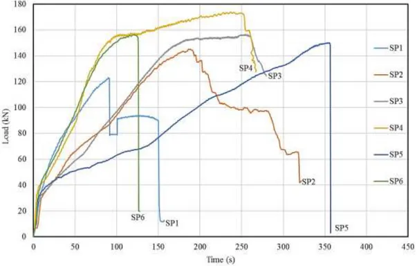
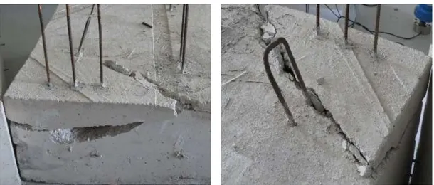
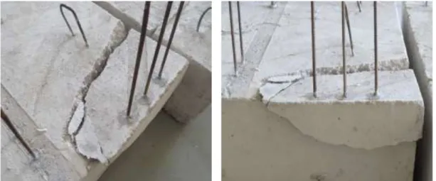
In five of tests, embedment depth was 12 cm and cone failure were observed. Only in one of tests, bond failure together with small cone damage was experienced. Steel failure from thread was observed in one of tests where embedment depth was 18 cm. Bond failure together with small cone damage was seen in three of tests and cone failure was observed in two tests. In the end of tests, the lowest load was 85.51 kN and the highest one was 173.81 kN. The maximum loads, failure type and compressive strength at the day of the test are given in Table 4.1. For anchors of diameter 12 mm, steel grade S420a and embedment depth 18 cm and 12 cm the load-time graphics are shown in Figure 4.1 and Figure 4.2, respectively. Test images for anchors of diameter 12 mm, steel grade S420a are shown in Figure 4.3-14.
32
Table 4.1 : Test results for S420a 12 mm group anchors. Specimen
No
Test Name Maximum
Load (kN) Failure Type Concrete Compressive Strength at the Day of the Test (MPa) SP1 B-G-F12E18L12P 123.04 Steel (from thread) 14.6
SP2 B-G-F12E18L24 144.97 Bond 14.9 SP3 B-G-F12E18L18 156.58 Bond 14.8 SP4 B-G-F12E18L18P 173.81 Bond 14.8 SP5 B-G-F12E18L12 150.18 Cone 14.7 SP6 B-G-F12E18L6P 156.22 Cone 14.7 SP7 B-G-F12E12L18P 114.97 Bond 14.9 SP8 B-G-F12E12L24P 122.15 Cone 14.9 SP9 B-G-F12E12L18 115.49 Cone 14.9 SP10 B-G-F12E12L12P 115.77 Cone 14.9 SP11 B-G-F12E12L24 99.84 Cone 14.9 SP12 B-G-F12E12L6 85.51 Cone 14.9
Figure 4.1 : Load (kN) – Time (s) graphic for 12 mm S420a anchors with 18 cm embedment depth.
33
Figure 4.2 : Load (kN) – Time (s) graphic for 12 mm S420a anchors with 12 cm embedment depth.
Figure 4.3 : Test images for Specimen 1.
34
Figure 4.5 : Test images for Specimen 3.
Figure 4.6 : Test images for Specimen 4.
35
Figure 4.8 : Test images for Specimen 6.
Figure 4.9 : Test images for Specimen 7.
36
Figure 4.11 : Test images for Specimen 9.
Figure 4.12 : Test images for Specimen 10.
![Figure 1.9 shows type of load under which anchors are subjected as given at ACI 355.2 [15]](https://thumb-eu.123doks.com/thumbv2/9libnet/3711215.24965/36.892.132.695.468.942/figure-shows-type-load-anchors-subjected-given-aci.webp)