Research Journal
Volume 10, No. 31, Sept. 2016, pages 51–57
DOI: 10.12913/22998624/64153 Research Article
EFFECT OF SILICON CONTENT ON MACHINABILITY OF Al-Si ALLOYS
Birol Akyüz11 Department of Mechanical and Manufacturing Engineering, Bilecik Seyh Edebali University, 11200 Bilecik,
Turkey, e-mail: [email protected]
ABSTRACT
In this study the effect of the change in the amount of Silicon (Si) occuring in Al-Si alloys on mechanical and machinability properties of the alloy was investigated. The change in mechanical properties and microstructure, which depends on the increase in Si percentage, and the effects of this change on Flank Build-up (FBU), wear on the cutting edge, surface roughness, and machinability were also studied. Alloys in differ-ent ratios of Si (i.e. 2 to 12 wt %), were employed in the study. The specimens for tests were obtained by casting into metal moulds. The results obtained from experimental studies indicate improved mechanical properties and machinability, depending on the rise in Si percentage in Al-Si alloys. It is also observed that the increase in Si percent-age enhanced surface quality.
Keywords: machining, cutting force, mechanical properties, Al-Si alloys
INTRODUCTION
Today, aluminium alloys are commonly used in numerous industries, predominantly in trans-port, automotive, aerospace and aviation indus-tries [1-8]. The most important properties of alu-minum alloys; in addition to aluminium alloys being plentiful in nature, its facility to produce, machine, and mould, being lightweight and its improvable mechanical properties also increase the place of use and the importance of these al-loys even more in today’s industries [9-12].
Some aluminium alloys are quite important materials used in the manufacturing of various parts, predominantly in automotive, transport, aviation and aerospace sectors, in order to lower emissions that are harmful to the environment (SOX, CO2, and NOX emissions) and to use en-ergy resources efficiently through weight de-creases [2, 3-6]. Within this scope, among the significant aluminium alloys most commonly used in today’s industries is Al-Si alloys [4, 7, 8, 10]. It is observed that the studies conducted on aluminium alloys generally focus on such subjects as microstructure and mechanical prop-erties analyses, hardness and creep propprop-erties
analysis, porosity formation, ageing characteris-tics and surface roughness analyses.
As a result of our literature reviews, studies that investigate the effect of the change in Si percent-age in Al-Si alloys on cutting forces (on machin-ability) and that also analyse wear on cutting edge and Flank build-up (FBU) are non-existent.Al-Si aluminium alloys containing Si% in different ra-tios (including Silicon in the rara-tios of 2 to 12 wt%) were used in this study. In the study, the effects of the change in Si% amount on microstructure, XRD, mechanical properties, cutting forces (machinabil-ity), chip formation, wear on the cutting edge, and Flank Build-Up (FBU) were investigated. Within this scope, this study bears an original quality.
EXPERIMENTAL PROCEDURE
Microstructural, XRD and mechanical properties
Al-Si alloys containing Si at variable rates (from 2% Si to 12% Si) were used in the experi-mental study. Experiexperi-mental samples were ob-tained by casting in Metal moulds. In obtaining the experimental samples, pure aluminium (Al-8E, Received: 2016.06.24
Accepted: 2016.07.11 Published: 2016.09.01
99.8%) and eutectic Etial 140 alloy with 12.5% Si content (12.5%Si, 0.6%Fe, 0.4%Mn, 0.1%Cu, 0.1%Zn, 0.1%Mg, 0.1%Ni, 0.1%Ti, 0.1%Pb con-tent) were used. Melting processes were carried out with an induction furnace (35 KW Inducto-therm). For the casting samples, when molten metal reached the temperature of ~720°C, it was kept at this temperature for 30min and then was cast in metal moulds. Moulds were designed so as to obtain 4 cylindrical samples in each mould for casting the experimental samples. At the end of casting, at least 16 cast samples were obtained from each of the alloys. Diameter of experimen-tal samples taken from the mould was 24mm and length was 200mm. In order to modify primer Si crystals with sharp corners that might occur due to fast cooling in the mould during the casting of Al-Si alloy (eutectic) containing 12%Si, phosphor bronze (CuSn5) was added to molten alloy at ppm level (20g in 0.002g/7400g pot). Mould filling time of casts was established as 8-10sec. Chemi-cal compounds of Al-Si alloy experimental sam-ples used in the experiment are given in Table 1.
In the experimental study, 6 experimental samples (with a diameter of 15 mm and a thick-ness of 10mm) were prepared from each series to be used in microstructure analyses of Al-Si alloys. Sample surfaces were cleaned by sand-ing (with emery papers startsand-ing from 200 grits up to 1200). Surfaces of samples used in micro-structure analyses were polished with diamond abrasives (6μm, 3μm, and 1 μm diamond paste, respectively). Sample surfaces were etched (for 20-25 seconds) with the prepared etching solu-tion (Keller solusolu-tion 2%HF, 3%HNO3, 95%H2O). Microstructural surveys were conducted on the metallographic samples by optical microscopy (LV150 Nikon Eclipse). The hardness values of the samples were determined by the Vickers hard-ness test (HV) with a load of 0.1N and 10N by using microhardness tester (Shimadzu HMV-2). At least ten hardness measurements were carried
out on each sample. XRD (X-ray diffraction anal-yses) (Panalytical-Empyrean) were carried out under Cu Kα radiation with an incidence beam angle of 2°. The microstructures of the samples were examined using optical microscopy (OM) and scanning electron microscopy.
Tensile tests were carried out. Data on the ten-sile strengths of alloys (Ultimate Tenten-sile Strength-UTS) and elongation % (El%) values were ob-tained from tensile tests. Samples used in the ten-sile tests were prepared in compliance with ASTM E 8 M-99 standards. Tensile test data were estab-lished by averaging 6 samples. Tensile tests were carried out at room temperature (20ºC) (Shimadzu Autograph AGS-J 10 kN Universal Tester). The strain rate used for tensile testing was 1.1×10⁻³ s−1.
Machining properties
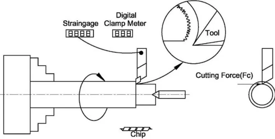
Machinability tests were carried out on CNC turning lathe (2.2 KW Boxford 250). Turning procedures were conducted under dry machin-ing conditions by usmachin-ing Polycrystalline Diamond (PCD-Taegutec CCGT 120408 FL K10) cutting edge and by orthogonal cutting method. Data on cutting forces established in the study were ob-tained by measuring with a specially designed and produced strain-gauge (Fig. 1).
In machinability experiments, changes in the cutting speeds were measured (by keeping the chip section fixed) at varying cutting speeds of Al-Si alloys Data on the machinability of al-loys based on the changes in cutting forces were prepared in graphics. Data on surface roughness values (Ra-µm) formed depending on the changes in alloy properties and machining parameters (Mi-tutoyo SJ210) were obtained. Before commencing the machinability experiments, cylindrical turning procedure was carried out in order to clean the sur-faces of samples. After the sample sursur-faces were
Table 1. Chemical composition of the studied Al-Si
alloys Al-Si Alloys Si Zn Mn Cu Fe Al 2%Si 2.15 0.02 0.01 0.01 0.04 rest 4%Si 4.28 0.02 0.01 0.01 0.04 rest 8%Si 8.12 0.02 0.01 0.01 0.04 rest 12%Si 11.70 0.02 0.01 0.02 0.05 rest
Table 2. Machining parameters and conditions used
during the test
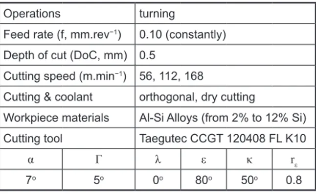
Operations turning
Feed rate (f, mm.rev−1) 0.10 (constantly)
Depth of cut (DoC, mm) 0.5 Cutting speed (m.min−1) 56, 112, 168
Cutting & coolant orthogonal, dry cutting
Workpiece materials Al-Si Alloys (from 2% to 12% Si) Cutting tool Taegutec CCGT 120408 FL K10
α Γ λ ε κ rε
7o 5o 0o 80o 50o 0.8
wt %, “Al” refers to Aluminum content and “Si” refers to Silicon content of the alloy.
cleaned, (following the pre-cleaning chip was removed by decreasing the diameter of samples from 24 mm to 20 mm) then experiments for mea-suring cutting forces were conducted. In machin-ability experiments, feed rate was kept fixed (0.10 mm.rev−1). Machining parameters used in the
ex-perimental study are given in Table 2.
EXPERIMENTAL RESULTS AND
DISCUSSION
Microstructural, XRD and mechanical properties
Microstructure images of Al-Si alloys used in the study can be found in Figure 2(a-d). When examined Figure 2(a-d), it was observed that the silicon in microstructure was distributed inside the structure, became significant/increased (Fig.
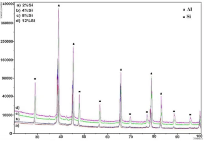
2d) depending on the Si% amount in the alloy. In Figure 3, XRD pattern belonging to Al-Si al-loys. Microstructure images and XRD pattern obtained in this study is in compliance with lit-erature [1, 8-11, 13].
Data on mechanical properties of Al-Si alloys used in the experiment can be observed (Fig. 4 and Fig. 5). The hardness of the analysed alloys was observed as in an order on a gradual increase from Al-Si containing 2%Si to Al-Si alloy con-taining 12%Si (Fig. 4).
While the lowest hardness value was obtained from Al-Si alloy containing 2%Si as 45.7HV10, the highest hardness value was obtained as 68.4 HV10 from the Al-Si alloy containing 12%Si. De-pending on the increase in Si amount in the alloy, an increase (~50%) was observed in the hardness of the alloy containing 12%Si (compared to the alloy containing 2%Si. The reason for the alloy to manifest an increase in hardness depending on
Fig. 1. Schematic representation of experimental set-up with strain
the amount of Si% in alloy was believed to be the effect of Si observed/found in microstructure depending on the addition of Si.
In the conducted experimental study, data ob-tained from tensile tests of Al-Si alloy samples are observed in the graph in Figure 5. As it can be observed from the graph, UTS values increased depending on the rise in Si amount in alloy, how-ever, EL% decreased.
Machining properties
In the conducted machinability experi-ments, chip section was kept fixed at different
cutting speeds and thus data on cutting forces of Al-Si alloys were obtained (Fig. 6). It was observed in the study that machinability of al-loys increased depending on the increase in Si% amount in the alloy (Fig. 6). In the experi-ment, it was found that cutting forces at lower cutting speeds were higher and that cutting forces decreased depending on increases in Si% amount in alloy (Fig. 6). While the high-est cutting force value in machinability experi-ments (at all cutting rates) was obtained from Al-Si alloy containing 2%Si, the lowest cutting force value (at all cutting rates) was found in the Al-Si alloy containing 12%Si (Fig. 6). Cut-ting forces (at all cutCut-ting rates) were ordered in a gradual decrease starting from Al-Si alloy containing 2%Si down to the alloy containing 12%Si (Fig. 6). While the cutting force value was measured as 34.7N in Al-Si alloy contain-ing 2%Si at the lowest cuttcontain-ing rate (at 56m/ min), it was measured as 21.9N in Al alloy containing 12%Si. With the increase in cutting rate (to 168 m/min), it was measured as 21.4N in Al-Si alloy containing 2%Si and as 17.9N cutting force in Al-Si alloy containing 12%Si. Therefore, when comparing the machinability of alloys containing 2%Si and 12%Si, an in-crease was observed in the machinability of al-loy containing 12%Si.
Decrease in cutting forces depending on the rise in the Si% amount in alloy manifests the ef-fect of Si in alloy. Depending on the Si amount in alloy, it may be noted that silicon observed in the microstructure becoming significant/increasing facilitated chip breaking [9–14] thus showed an impact in a form of a decrease in cutting forces. From this point of view, it may be noted that the machinability of alloy increased depending on the rise in Si amount in alloy in Al-Si alloys. Cutting forces were also observed as higher at lower cut-ting rates. The reason for this was the build-up of
Fig. 3. XRD patterns of Al-Si Alloys
30 40 50 60 70 80 2% 4% 8% 12% Al-Si Alloys Hard ness, HV 0.1 N 10 N
Fig. 4. Hardness (HV) of Al-Si alloys
0 50 100 150 200 250
2%Si 4%Si 8%Si 12%Si Al-Si Alloys U lti m at e T en sil e S tren gt h, U TS , M pa 0 2 4 6 8 10 12
2%Si 4%Si 8%Si 12%Si
Al-Si Alloys El on gat ion ,E L, %
chips as a result of dislocation build-up at lower cutting rates (deformation hardening/work hard-ening) [15-20].
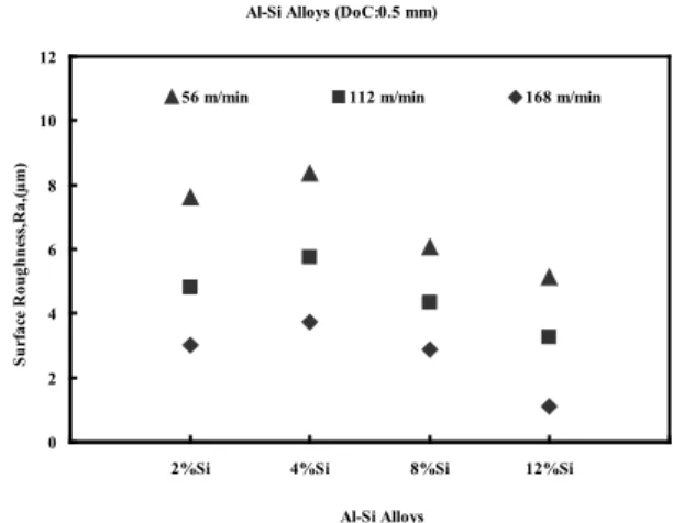
Data on surface roughness of alloys used in the experiment are observed in Figure 7. Surface roughness values were ordered manifesting a de-crease beginning from the alloy containing 2%Si down to Al-Si alloy containing 12%Si. It was ob-served in the study that surface roughness values decreased (finer surfaces were obtained) depend-ing on the rise in Si amount in the alloy in Al-Si alloys and on the increase in cutting rate (from 2%Si to 12%Si).
When examined in the study chips obtained from processing the samples (Fig. 8), chip lengths changed depending on the Si amount in the alloy and on the rise in cutting rate. It was observed that Si found in microstructure was effective in chip formation depending on the increase in the Si% amount in alloy. When comparing chips obtained from Al-Si alloy
containing 12%Si with others, chips were ob-served as formed at shorter lengths (showing brittle breaking behaviour and discontinuous chip formation) as a result of chips manifest-ing more brittle/fragile behaviour (thanks to Si) due to alloy being harder. From this point of view, it may be noted that the increase in Si amount in Al-Si alloys affects chip lengths to be shorter.
Images of the surfaces of cutting edge used in the experiment are observed in Figure 9. Flank Build-up (FBU) was observed on cutting edge sur-faces due to dry adhesion between the work piece and cutting edge surface (Fig. 9). It was observed that this build-up (FBU) was more on the cutting edge belonging to Al-Si alloy containing 2%Si and that it spread more broadly on continuous chip sur-face (Fig. 9a). In the alloy containing 12%Si, chip build-up (FBU) was observed as lower, however, wear occurred at the tip more and was deeper (Fig.
Al-Si Alloys (DoC:0.5 mm)
10 20 30 40 50 0 56 112 168 224
Cutting Speed (m/min)
Fo rce( N ) 2%Si 4%Si 8%Si 12%Si
Fig. 6. Relationship between cutting forces and Al-Si
alloy compositions (DoC:0.5 mm, f:0.10 mm/rev)
Al-Si Alloys (DoC:0.5 mm)
0 2 4 6 8 10 12
2%Si 4%Si 8%Si 12%Si
Al-Si Alloys Sur fa ce R oug hne ss ,R a, (µ m )
56 m/min 112 m/min 168 m/min
Fig. 7. Relationship between surface roughness and
cutting speeds of Al-Si alloys (DoC:0.5 mm)
9h). FBU was observed to occur on the tip surface of the cutting edge from the wider surface towards the narrower surface depending on the increase in Si% amount in alloy (Fig. 9). A similar case occurs due to a rise in the cutting rate.
In the experimental study, mechanical proper-ties and machinability of alloys were observed to increase depending on the Si% amount in Al-Si alloys (Fig. 4-6). It was found that chip breaks were facilitated and that this showed an effect in a form of a decrease in cutting forces thanks to the rise in Si% in alloy (due to the effect of Si). Especially in Al-Si alloy containing 12%Si, the occurrence of lower cutting force shows that Si in the structure has a positive effect on the machina-bility of Si [13-15].
It was observed that cutting forces were greater at lower cutting rates. The reason for cut-ting forces being greater at lower cutcut-ting rates may be noted as chip build-up (FBU) adhesion on cutting edge due to increase in dislocation build-up (deformation hardening/work hardening effect) [15-17] and local heating due to friction. From this point of view, Si presence in Al-Si al-loys (increase in Si% amount) shows an effect in the form of decreasing cutting forces and machin-ability increases depending on the former.
It was observed in the study that a rise in Si amount in Al-Si alloys had a positive effect on mechanical properties and machinability proper-ties of the alloy. The data obtained from the previ-ous sections of the study (Fig. 2-5) and data ob-tained from the mechanical test results (Fig. 6-9) machinability section support each other. The data obtained from the study are in compliance with literature [1-14].
CONCLUSIONS
The below-mentioned results were obtained from the experimental study:
1. Mechanical properties of Al-Si alloys were observed as increased depending on the Si% amount in Al-Si alloys used in the experiment. On the other hand, El% decreased.
2. It was observed that the increase in Si% amount in the Al-Si alloys (Si observed in mi-crostructure becoming significant) had an ef-fect in the form of a decrease in cutting forces. Machinability of Al-Si alloys increased de-pending on the decrease in cutting forces. 3. Cutting forces were observed as higher at
lower cutting speeds. Cutting forces were ob-served to decrease along with the increase in cutting speed. The highest cutting force were found to occur in the alloy containing 2%Si. 4. In Al-Si alloys, surface roughness values were
observed as on a decrease (finer surfaces) in-versely due to increase in Si amount in alloy. Surface roughness values were observed as higher (rougher surfaces were formed) at low-er cutting speeds.
5. Increase in Si% amount in alloy was observed to have an effect on chip formation. Chips were observed to form at shorter lengths de-pending on the increase in Si% amount in al-loy and cutting speed. Chips were observed to form at shorter lengths in Al-Si alloy (contain-ing 12%Si) at higher hardness due to the effect of silicon chips were formed at longer lengths in 2%Si alloys.
Fig. 9(a-h). SEM image of cutting tool tip used for machining of Al-Si alloys (Vc:56-168 m/min, DoC:0.5 mm, f:0.10 mm/rev)
6. It was observed that the increase in Si amount affected Flank Build-up (FBU for-mation on cutting tool edge and on cutting forces formation. It was observed that FBU spread on the cutting edge surface at lower cutting speeds, and that FBU formation was higher in Al-Si alloy containing 2%Si that had higher ductility.
REFERENCES
1. Shi W.X., Gao B., Tu G.F., Li, S.W.: Journal of Alloys and Compounds 508, 2010, 480–485, doi:10.1016/j.jallcom.2010.08.098
2. Mohamed A.M.A., Samuel A.M., Samuel, F.H., Doty, H.W.: Materials and Design 30, 2009, 3943– 3957, doi:10.1016/j.matdes.2009.05.042 .
3. Ogawa T., Haruyama S., Era H., Kishitake, K.: Materials Transactions, 46(8), 2005, 1771–1774. 4. Onyia C.W., Okorie B.A., Neife S. I., Obayi, C.S.:
World Journal of Engineering and Technology, 1, 2013, 9-16.
5. Roy P., Sarangi S.K. , Ghosh A. , Chattopadhyay, A.K.: Int. Journal of Refractory Metals & Hard Materials 27, 2009, 535–544. doi:10.1016/j.ijrm-hm.2008.04.008.
6. Guru P.R., Kan MD F., Panigrahi S.K., Ram, G.D.J.: Journal of Manufacturing Processes 18, 2015, 67–74, http://dx.doi.org/10.1016/j. jmapro.2015.01.005.
7. Hu X., AI F. Yan H: Acta Metall. Sin. (Engl. Lett.) 25(4), 2012, 272-278.
8. Zedan Y., Samuel F.H., Samuel A.M., Doty,
H.W: Journal of Materials Processing Technol-ogy 210, 2010, 245–257, doi:10.1016/j.jmatpro-tec.2009.09.007.
9. Saravanan R., Sellamuthu R.: Procedia Engineer-ing 97, 2014, 1348–1354, doi: 10.1016/j.pro-eng.2014.12.415.
10. Zedan Y., Alkahtani S.: Journal of Materials Pro-cessing Technology 213, 2013, 167–179, http:// dx.doi.org/10.1016/j.jmatprotec.2012.09.007. 11. Rajinikanth V., Venkateswarlu K. , Sen, M.K., Das,
M., Alhajeri, S.N., Langdon, T.G.: Materials Sci-ence and Engineering A528, 2011, 1702–1706. doi:10.1016/j.msea.2010.10.102
12. Li Y., Tan Y., Li J., Xu Q., Liu Y.: Journal of Alloys and Compounds 583, 2014, 85–90, http://dx.doi. org/10.1016/j.jallcom.2013.08.145.
13. Kamiya M., Yakou T., Sasaki T., Nagatsuma Y.: Materials Transactions, 49(3), 2008, 587-592. 14. Steininger A., Siller A., Bleicher F.: Procedia
En-gineering 100, 2015, 1124–1132.
15. Stephenson D.A., Agapiou J.S.: Metal Cutting The-ory and Practice (2nd Ed.), Taylor & Francis, 2006. 16. Boothroyd G., Knight W.A.: Fundamentals of Ma-chining and Machine Tools, (3rd. Ed.), Taylor & Francis, 2006.
17. Kalpakjian S., Schmid S.R.: Manufacturing Engi-neering and Technology, Prentice Hall, 2010. 18. Grover M.P.: Principles of Modern Manufacturing
(4th Ed.), John Wiley & Sons, Inc., 2010.
19. Black J.T., Kohser R.A.: Materials&Processes in Manufacturing (10th Ed.), John Wiley & Sons, Inc.,
2008.
20. GrzesikW.: Advanced Machining Processes of Me-tallic Materials, Elsevier, UK., 2008.