EXPERIMENTAL INVESTIGATION OF
DOMESTIC DISHWASHER GREYWATER
THERMAL ENERGY RECOVERY BY COMPACT
HEAT EXCHANGER
2020
MASTER THESIS
ENERGY SYSTEMS ENGINEERING
KHALED MOHAMED ASHNAAF ABAJJA
EXPERIMENTAL INVESTIGATION OF DOMESTIC DISHWASHER GREYWATER THERMAL ENERGY RECOVERY BY COMPACT HEAT
EXCHANGER
Khaled Mohamed Ashnaaf ABAJJA
T.C.
Karabuk University Institute of Graduate Programs Department of Energy Systems Engineering
Prepared as Master Thesis
Assist. Prof. Dr. Selcuk SELIMLI
KARABUK September 2020
ii
I certify that in my opinion the thesis submitted by Khaled Mohamed Ashnaaf ABAJJA titled “EXPERIMENTAL INVESTIGATION OF DOMESTIC DISHWASHER GREYWATER THERMAL ENERGY RECOVERY BY COMPACT HEAT EXCHANGER” is fully adequate in scope and in quality as a thesis for the degree of Master of Science.
Assist. Prof. Dr. Selcuk SELIMLI ... Thesis Advisor, Department of Energy Systems Engineering
APPROVAL
This thesis is accepted by the examining committee with a unanimous vote in the Department of Energy Systems Engineering as a Master of Science thesis. Sept. 17, 2020
Examining Committee Members (Institutions) Signature
Chairman : Prof. Dr. Kurtulus BORAN (GU) ... Member : Prof. Dr. Mehmet OZKAYMAK (KBU) ... Member : Assist. Prof. Dr. Selcuk SELIMLI (KBU) ...
The degree of Master of Science by the thesis submitted is approved by the
Administrative Board of the Institute of Graduate Programs, Karabuk University.
Prof. Dr. Hasan SOLMAZ ...
iii
“I declare that all the information within this thesis has been gathered and presented in accordance with academic regulations and ethical principles and I have according to the requirements of these regulations and principles cited all those which do not originate in this work as well.”
iv
ABSTRACT M. Sc. Thesis
EXPERIMENTAL INVESTIGATION OF DOMESTIC DISHWASHER GREYWATER THERMAL ENERGY RECOVERY BY COMPACT HEAT
EXCHANGER
Khaled Mohamed Ashnaaf ABAJJA Karabuk University
Institute of Graduate Programs
The Department of Energy Systems Engineering Thesis Advisor:
Assist. Prof. Dr. Selçuk SELİMLİ September 2020, 69 pages
In this study, we investigated to recover heat energy by a heat exchanger which is in two different type is used from the greywater of the dishwasher to heat the tap water comes to the dishwasher during the washing process. We aimed to get saving from the consuming energy of dishwasher to heat water during the dishwashing process. Shell and tube, and shell and wire on tube type heat exchangers separately connected to the dishwasher during experimentations. Experiments were completed on the device, in two cases that were unloaded and loaded and in three different dishwashing programs such as economy, quick and intense. The saving rate was dependently compared and estimated for each program, type of attached heat exchanger and the load condition of the dishwasher. As a result, in unloaded case by the attachment of shell and tube heat exchanger, the saving rate were calculated about 1.49%, 1.90%, and 2.71% for
v
programs in the order as economy, quick and intense. In loaded case, the same experiments were repeated, and the saving rates were determined about 1.65%, 1.27%, and 4.17%. Then, we had changed the heat exchanger with shell and wire on tube type, and in the unloaded case the experiments were repeated to get the new configuration energy saving performance. For the case, the saving rates were assessed about 13.10%, 13%, and 16.68%, in some washing program order. Lastly, dishwasher was fully loaded again, and the experiments were done in the same order. The energy efficiency increase was gotten in this new configuration were reached about 14.11%, 15.48% and 15.70% for three programs. The average energy consumption of dishwasher with heat exchanger attachment under loaded case was calculated by estimating the average of three different programs dependently the usage habit of an average family under loaded case. Annual, 280 washing cycle consumption of an average family were determined about 51 kWh. The economic value of this saving approximately equals to $ 5.61 for per device by heat recovery application. The estimated price of the equipping a dishwasher with a heat exchanger approximately is $ 35. The payback period could be estimated about at least 6.2 years. By the saving of electricity, annual carbon emission of a dishwasher could be eliminated about 18.83 kg annually for per machine, too. The indirect positive effect of this study raising the awareness about the possibility of wasted energy recoverability from dishwashers to the producers and researchers who are busy to decrease energy consumption of these goods.
Key Words : Dishwasher, heat exchanger, greywater thermal energy recovery,
carbon emission.
vi
ÖZET Yüksek Lisans Tezi
EV TİPİ BULAŞIK MAKİNESİ ATIK SU TERMAL ENERJİSİNİN KOMPAKT ISI EŞANJÖRÜ İLE GERİ KAZANIMININ DENEYSEL
OLARAK ARAŞTIRILMASI
Khaled Mohamed Ashnaaf ABAJJA Karabük Üniversitesi
Lisansüstü Eğitim Enstitüsü
Enerji Sistemleri Mühendisliği Anabilim Dalı Tez Danışmanı:
Dr. Öğr. Üyesi Selçuk SELİMLİ Eylül 2020, 69 sayfa
Bu çalışmada, yıkama işlemi sırasında bulaşık makinesine alınan şebeke suyuna iki farklı ısı eşanjörü kullanarak bulaşık makinesi atık suyunun ısıl enerjisinin geri kazanımını araştırdık. Bulaşık yıkama sürecinde bulaşık makinesinin suyu ısıtmak için tükettiği enerjiden tasarruf sağlamayı amaçladık. Gövde borulu ısı değiştirici ve gövde borulu tel kanatlı ısı değiştirici olmak üzere ayrı ayrı bulaşık makinesine bağlanan eşanjörlerle deneyler tamamlanmıştır. Deneyler makinenin yüklü olmadığı ve yüklü olduğu iki farklı durumu ve üç farklı ekonomi, hızlı ve yoğun programları için tamamlandı. Tasarruf miktarı her bir programa, bağlanan ısı değiştiricinin türüne ve bulaşık makinesinin yüküne bağlı olarak karşılaştırıldı ve değerlendirildi. Sonuçta, bulaşık makinesinin yüklü olmadığı ve gövde borulu ısı değiştiricinin makineye bağlandığı durum için sağlanan tasarruf oransal miktarı yaklaşık olarak %1,49, %1,90,
vii
ve %2,71 olarak ekonomi, hızlı ve yoğun programları için hesaplandı. Yüklü durum için, aynı deneyler tekrarlandı ve tasarruf oransal miktarları %1,65, %1,27, ve %4,17 olarak belirlendi. Sonra, ısı değiştiricini gövde borulu tel kanatlı ısı değiştirici ile değiştirdik ve deneyleri bu yeni durum için makinenin yüklü olmadığı durumda tekrarlayarak enerji tasarrufu performansını elde ettik. Bu durumda, tasarruf oransal miktarları yaklaşık %13,10, %13, ve%16,68, olarak aynı program sırası ile belirlendi. Son olarak bulaşık makinesi tamamen yüklenerek deneyler aynı sırada tekrarlandı. Enerji verimindeki artış, bu yeni durumda yaklaşık%14,11, %15,48 ve %15,70 değerlerine üç farklı program için ulaştı. Bulaşık makinesinin ısı eşanjörü bağlantısı ile ortalama enerji tüketimi sıradan bir ailenin kullanım alışkanlıklarına bağlı olduğu için üç farklı programın enerji tüketimi ortalaması alınarak hesaplandı. Yıllık, ortalama bir ailenin 280 çevrim bulaşık yıkama süreci için enerji tüketimi 51 kWh olarak belirlendi. Enerji geri kazanımı ile tasarruf ekonomik değeri makine başına yaklaşık $ 5,61 olarak belirlendi. Bir bulaşık makinesinin ısı değiştirici ile donatımı yaklaşık olarak $ 35 olarak değerlendirilmektedir. Geri ödeme süresi 6,2 yıl olarak belirlenir. Yıllık makine başına 18,83 kg karbon emisyonunun elimine edilmesi elektrik tüketiminden sağlanan tasarruf ile mümkün olabilir. Çalışmanın dolaylı pozitif katkısı, bulaşık makinesi atık ısının geri kazanılabilirliği konusunda beyaz eşyaların enerji tüketiminin azaltılması konusuna ilgi duyan üreticiler ve araştırmacılarda farkındalığın artırılması ve katkı sunmasıdır.
Anahtar Kelimeler : Bulaşık makinesi, ısı eşanjörü, atık su termal enerjisi geri
kazanımı, karbon emisyonu.
viii
ACKNOWLEDGMENT
I extend my sincere thanks and gratitude to everyone who contributed or extended a helping hand to make this message of success, especially the supervisor, Assist. Prof. Dr. Selcuk SELIMLI, who helped me and spared no effort to reach us to this stage and overcome difficulties during this practical experience and write this letter to be successful. I also thank the Head of Energy Systems Engineering who chose the right supervisor for me. I also thank the University of Karabuk and its staff for their generous reception and harnessing their potential as possible to reach the best possible in the field of scientific research. For those I miss with all my feelings ... my dear homeland. An example of dedication and sincerity my father. To those who gave my happiness and comfort to her happiness my dear mother. To whom did you hold back my help one day my dear wife. To those who gave me advice and guidance dear brothers. To everyone who called me well. I offer you this humble work.
ix CONTENTS Page APPROVAL ... ii ABSTRACT ... iv ÖZET ... vi ACKNOWLEDGMENT ... viii CONTENTS ... ix LIST OF FIGURES ... xi
LIST OF TABLES ... xiv
SYMBOLS AND ABBREVITIONS INDEX ... xv
PART 1 ... 1
INTRODUCTION ... 1
1.1. DESIGN PARAMETERS OF HEAT EXCHANGERS ... 7
1.2. HEAT TRANSFER THEORIES ... 10
1.2.1. Heat Transfer in Same Directional with Flow Heat Exchangers ... 10
1.2.2. Heat Transfer in Opposite Directional with Flow Heat Exchangers ... 10
1.3. AUTOMATIC DISHWASHERS ... 11 PART 2 ... 13 LITERATURE REVIEW ... 13 PART 3 ... 18 THEORETICAL BACKGROUND ... 18 PART 4 ... 20 METHODOLOGY ... 20 PART 5 ... 26
x
Page
5.1. EXAMINING THE ECONOMY PROGRAM FOR THE CASE THAT THE
DISHWASHER IS UNLOADED ... 26
5.2. EXAMINING THE QUICK PROGRAM FOR THE CASE THAT THE DISHWASHER IS UNLOADED ... 31
5.3. EXAMINING THE INTENSE PROGRAM FOR THE CASE THAT THE DISHWASHER IS UNLOADED ... 36
5.4. EXAMINING THE ECONOMY PROGRAM FOR THE CASE THAT THE DISHWASHER IS LOADED ... 41
5.5. EXAMINING THE QUICK PROGRAM FOR THE CASE THAT THE DISHWASHER IS LOADED ... 46
5.6. EXAMINING THE INTENSE PROGRAM FOR THE CASE THAT THE DISHWASHER IS LOADED ... 51 PART 6 ... 57 CONCLUSIONS ... 57 PART 7 ... 60 SUMMARY ... 60 RECOMMENDATIONS ... 61 REFERENCES ... 63 RESUME ... 69
xi
LIST OF FIGURES
Page
Figure 4.1. The scheme of experimentation setup. ... 20
Figure 4.2. Shell and tube heat exchanger. ... 21
Figure 4.3. Shell and wire on tube heat exchanger. ... 21
Figure 4.4. The experimentation setup and its components. ... 22
Figure 4.5. The temperature reading points on the experimentation setup. ... 23
Figure 4.6. The shell and tube heat exchanger with (a) and without (b) heat isolation. ... 24
Figure 4.7. The shell and wire on tube heat exchanger with (a) and without (b) heat isolation. ... 25
Figure 5.1. Temperature variation during the economy cycle in unloaded case of dishwasher without heat exchanger attachment. ... 26
Figure 5.2. Temperature variation during economy cycle in unloaded case of dishwasher with shell and tube heat exchanger. ... 27
Figure 5.3. Temperature variation during economy cycle in unloaded case of dishwasher with shell and wire on tube heat exchanger. ... 28
Figure 5.4. Comparison of the temperature of the water entering the dishwasher in the economy program unloaded. ... 29
Figure 5.5. The rate of reduction in energy, and time consumption by the attachment of the heat exchangers to dishwasher in unloaded case and economy cycle. ... 30
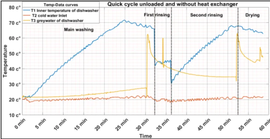
Figure 5.6. Temperature variation during quick cycle in unloaded case of dishwasher without heat exchanger attachment. ... 31
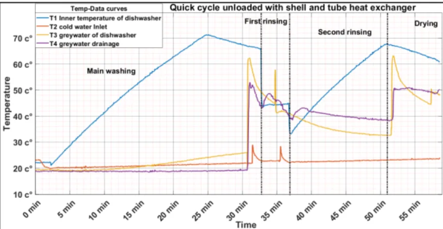
Figure 5.7. Temperature variation during quick cycle unloaded case of dishwasher with shell and tube heat exchanger attachment. ... 32
Figure 5.8. Temperature variation during quick cycle in case of dishwasher is unloaded with shell and wire on tube heat exchanger. ... 33
Figure 5. 9. Comparison of the temperature of the water entering the dishwasher in the quick cycle unloaded. ... 34
xii
Page
Figure 5.10. The rate of reduction in energy, and time consumption by the
attachment of the heat exchangers to dishwasher in unloaded case and quick cycle. ... 35 Figure 5.11. Temperature variation during intense cycle in unloaded case of
dishwasher without heat exchanger attachment. ... 36 Figure 5.12. Temperature variation during intense cycle in unloaded case of
dishwasher with shell and tube heat exchanger attachment. ... 37 Figure 5. 13. Temperature variation during intense cycle in unloaded case of
dishwasher with shell and wire on tube heat exchanger attachment. .... 38 Figure 5.14. Comparison of the temperature of the water entering the dishwasher in
the intense cycle unloaded. ... 39 Figure 5.15. The rate of reduction in energy, and time consumption by the
attachment of the heat exchangers to dishwasher in unloaded case and intense cycle. ... 40 Figure 5. 16. Temperature variation during economy cycle in loaded case of
dishwasher without heat exchanger attachment. ... 41 Figure 5. 17. Temperature variation during economy cycle in loaded case of
dishwasher with shell and tube heat exchanger attachment. ... 42 Figure 5.18. Temperature variation during economy cycle in loaded case of
dishwasher with shell and wire on tube heat exchanger attachment. .... 43 Figure 5.19. Comparison of the temperature of the water entering the dishwasher in
the economy cycle with loaded. ... 44 Figure 5.20. The rate of reduction in energy, and time consumption by the
attachment of the heat exchangers to dishwasher in loaded case and economy cycle. ... 45 Figure 5.21. Temperature variation during quick cycle in loaded case of dishwasher
without heat exchanger attachment. ... 46 Figure 5.22. Temperature ariation during quick cycle in loaded case of dishwasher
with shell and tube heat exchanger attachment. ... 47 Figure 5.23. Temperature variation during quick cycle in loaded case of dishwasher
xiii
Page
Figure 5.24. Comparison of the temperature of the water entering the dishwasher in the quick cycle with loaded. ... 49 Figure 5.25. The rate of reduction in energy, and time consumption by the
attachment of the heat exchangers to dishwasher in loaded case and quick cycle. ... 50 Figure 5.26. Temperature variation during intense cycle in loaded case of dishwasher without heat exchanger attachment. ... 51 Figure 5.27. Temperature variation during intense cycle in loaded case of dishwasher with shell and tube heat exchanger attachment. ... 52 Figure 5.28. Temperature variation during intense cycle in loaded case of dishwasher with shell and wire on tube heat exchanger attachment. ... 53 Figure 5.29. Comparison of the temperature of the water entering the dishwasher in
the intense cycle with loaded. ... 54 Figure 5.30. The rate of reduction in energy, and time consumption by the
attachment of the heat exchangers to dishwasher in loaded case and intense cycle. ... 55
xiv
LIST OF TABLES
Page
Table 5.1. The energy consumption of the dishwasher for unloaded case and the economy cycle. ... 30 Table 5.2. The energy consumption of the dishwasher in unloaded case of
dishwasher for the quick cycle. ... 35 Table 5.3. The energy consumption of the dishwasher in unloaded case of
dishwasher for the intense cycle. ... 40 Table 5.4. The energy consumption of the dishwasher in loaded case of dishwasher
for the economy cycle. ... 45 Table 5.5. The energy consumption of the dishwasher in loaded case of dishwasher
for the quick cycle. ... 50 Table 5.6. The energy consumption of the dishwasher in loaded case of dishwasher
for the intense cycle. ... 55 Table 5.7. Energy efficiency classes [53]. ... 59
xv
SYMBOLS AND ABBREVITIONS INDEX SYMBOLS
𝐴 : Heat transfer area
𝐴 : Outer heat exchange surface area 𝐴 : Outer heat exchange surface area
𝐴𝐸𝑐 : Annual energy consumption of the household dishwasher 𝑐 : Specific heat
𝐷 : Inner diameter of tube 𝐷 : Outer diameter of the tube 𝐸𝐸𝐼 : The energy efficiency index 𝑓 : The inner side friction coefficient ℎ : Inner side heat transfer coefficient ℎ : Outer side convection coefficient 𝑘 : Thermal conductivity
𝑚 : Mass flow rate
𝑅 : Total thermal resistance 𝑅 : Inner thermal resistance 𝑅 : Outer thermal resistance 𝑅𝑒 : Reynolds number 𝑃𝑟 : Prandtl number 𝑄 : Heat transfer rate
𝑆𝐴𝐸𝑐 : Standard annual energy consumption of the household dishwasher ∆𝑇 : Temperature difference
𝑇 : Inlet temperature 𝑇 : Outlet temperature
∆𝑇 : Logarithmic mean temperature difference 𝑇 , : Inlet hot fluid temperature
xvi 𝑇 , : Outlet cold fluid temperature
𝑈 : Overall heat transfer coefficient
ABBREVITIONS
𝑊𝑊𝐻𝑅 : Waste Water Heat Recovery
𝑃𝑁 − 𝐸𝑁 12056 − 1: 2002 : International Standard for Greywater Reuse
𝐶𝑂𝑃 : Coefficient of Performance
1
PART 1 INTRODUCTION
Technological developments increase in income and well-being, easy access, and increase in the amount of consumption cause large consumption of energy sources, and thus consumption that increases the rates of environmental pollution. Where the residential sector represents about 25% of global energy consumption and 17% of global CO2 emissions [1]. Increased energy demand, observed worldwide, is forced to
take measures aimed at managing it more effectively. The European Union countries are applying with regard to improving energy efficiency by increasing the share of renewable energy sources and reducing the negative impact of the energy economy on the environment. One practical way to achieve these goals is to use waste heat from wastewater. Currently, many European countries are implementing technical solutions that allow the recovery of part of the lost heat and the management of recovered energy as an alternative energy source for the building, for heating water or heating buildings or as a source of refrigeration for air conditioning during the summer. All this can be accomplished by using appropriate devices such as heat exchangers that can be installed in buildings and sewage systems [2]. Gray wastewater is water consumed from bathtubs, automatic washing machines, or dishwashers. a temperature of about 30 °C. In the regulations an important reference is the record number PN-EN 12056-1: 2002 for the possibility of using gray wastewater, separating the greywater sewage system to install a heat recovery system [3]. Modern technologies allow the collection of heat from wastewater also in its transmission stages, i.e. in the collecting tube. The temperature of the wastewater decreases before it flows to the wastewater treatment plant, which can adversely affect the biological processes taking place there [4]. Sewage heat energy can be obtained in several places in the sewage system: near the place of its formation and its exit to the sewage system, in its transmission stage, i.e. in the collecting pipe, and when the collector exits the sewage treatment plant, near the hot water outlet from hardware [5].
2
Domestic greywater could be evaluated as energy losing point of houses because 60% of the water is heated to use in showers, sinks, dishwashers, and clothes washers. This heat, nowadays lost into the sewer system, could be make the greywater a carrier of heat [6]. Recently, investigations on improving energy efficiency are getting more important for domestic appliance sector like the other sectors [7]. There are various design options for improving the energy efficiency of dishwashers, which show the potential for energy savings [8]. These reports published with design options that have technical feasibility in the future and provide economically low energy consumption values for the consumers [9,10].
There are two ways to achieve dishwashing thermal improvement: • Increase thermal insulation
• Reduce cabin energy storage
Reducing energy storage in the cabinet is possible by using materials with a lower thermal capacity. Steel, which is generally used, has a much lower heat storage coefficient (0.5 kJ/kg °C) than most materials including polypropylene (1.3-1.7 kJ / kg °C). These values indicate that at least 3 times lighter construction is required to use polypropylene as the boiler material [11]. Recovery of the waste heat energy of dishwasher greywater line could be a new subject of the researchers and producers who are working on the field to decrease energy consumption of the dishwashers. In this thesis, we have tried to recover the heat from the drain greywater of a dishwasher to preheat the refill water. We aimed to decrease energy usage of the dishwasher for per cycling dishwasher process. A household dishwasher has some of different washing procedures. Most of the dishwashers have quick, economy, and intensive programs to use. Each program has subprocesses due to the load and time requirements. Quick program generally specialized for lightly soiled dishes, to clean them speedily. It composts main washing, rinsing and drying subprocesses. Economy program or called normal program is a daily useable program for normally dirty dishes. It generally consists prewashing, main washing, rinsing and drying subprocesses. Intensive program is the heavily soiled dishes cleaning requirement could be satisfied with an order of sub processes that are prewashing, main washing, first rinsing, second
3
rinsing and drying. Some of the sub processes needs heating of water and at the end of process heated water is directly rejected to the drain. The heat content of this drained water could be saved to the refill water of the ongoing water required process. In this thesis, a compact heat exchanger attachment is between the drain line of the dishwasher and the refill tap water line was studied. Devices for which heat transfer between the hot fluid and the cold fluid are generally referred to as heat exchangers. Heat exchangers are a good field of application of materials, strength, thermodynamics, and heat transfer science which are the basic subjects of engineering branches. In engineering applications, heat transfer between two or more fluids at different temperatures is important. The heat transfer between the fluids takes place by conduction and convection. Fluids often used in heat exchangers are separated by a solid surface, which is generally metal material, where heat transfer is carried out without mixing with each other. Such heat exchangers are called surface heat exchangers. Heat exchangers are used in various processes; they are used in power, automotive, air-conditioning, cooling, cryogenics, heat economy, manufacturing industry, electronic devices, and alternative energy sources. They can be in different designs, sizes, types, and capacities depending on the purpose of use. The design of the heat exchangers is quite complex. Heat transfer, pressure drop analysis, dimensioning, size, performance determination and economical are important factors for design. Cost-effective factors for power plants and chemical processing units are among the key factors in places that require extensive placement and use, but the weight and size limitation is the deciding factor.
By combining the pipes in which hot and cold fluids flow, and by assembling the ends of the pipes in a sleeve, it is possible to obtain large heat transfer surfaces in a very economical and practical manner. The simplest of these types of heat exchangers are single pass. If the current in the pipes is low, low heat transfer coefficient and low pressure drop. Disadvantages due to low speed in single pass hot flow pipes can be removed by using multiple pass pipes [12]. A multi-pass design reduces the cross section of the fluid but increases the fluid speed. As a result, heat transfer coefficient, friction losses and input losses increase. If a heat exchanger is economically designed, the increased energy consumption for pumping the fluid in the pipes must be met by a reduction in the cost of the device. In these heat exchangers, the pumping costs at low
4
speeds are also low, but the heat exchange is too slow. Therefore, the increase in speed increases both energy consumption and heat exchange. If more than one pipe is required for each inlet, a double pipe heat exchanger is recommended as the simplest heat exchanger. This type of heat exchanger consists mainly two pipes in the same center. The fluid flows through the internal pipe, while the other flows in parallel or in the opposite direction, through the spaces between the pipes [13]. In the heat exchangers, the works for saving materials and energy have increased. Especially because the world is entering into a big energy bottleneck, more efficient use of existing energy comes to the fore. For this purpose, the design of smaller size heat exchangers for a certain capacity has been prioritized. By using techniques to increase the efficiency of heat transfer, it is aimed to reduce the size of the heat exchangers, increase the thermal efficiency by adapting the different flow profiles while reducing the need for pumping and additional energy. By reducing the temperature difference between hot and cold fluids and improving the heat transfer coefficient, the efficiency of the heat exchangers is increased.
The heat exchangers used in practice are classified according to the following parameters:
• Form of heat transfer process • Unit volume of heat transfer area • Design shape
• Flow regulation of fluids • Heat transfer mechanism
According to that, heat exchangers can be examined in two classes as direct-contact and indirect-contact heat exchangers. In the direct-contact heat exchangers, the heat is transferred from the hot fluid in contact with each other to the cold stream. Generally, one of the fluids is liquid and the other one is the vapor pressure is very low. In the case of indirect-contact heat exchangers, the heat is first transferred from the hot fluid to the wall separating the two fluids and from the wall to the cold fluid [14]. According to the shape of the structure, heat exchangers can be grouped as tube, sheet, flap-tube, vane-plate and regenerative heat exchangers. Tube heat exchangers are easily
5
manufactured and cheap and are the most widely used heat exchangers in practice. It generally consists of a bundle of tubes placed in a cylindrical body. Routers are used to guide the flow and support the pipe bundle. One fluid flow through the tube bundle and the other. The flow of two fluids is also provided by pumps. Heat transfer mechanism is also forced transport. If one of the fluids is gas, fins are added to the surface of the gas fluid to increase the heat transfer area. The cylindrical body is closed by two ends [15].
Tube heat exchangers: in this type of heat exchangers, elliptical, rectangular and generally circular section pipes are used. It provides great convenience in projecting due to the easy change of pipe diameter, length and arrangement. In addition, this type of heat exchangers can be used at high pressures because the circular section pipes can withstand high pressures compared to other geometric shapes. In practice, as well as double-pipe ones, varieties made of pipe bundle are also found. The ones with double pipes are the simplest type of heat exchanger. The system is usually made of two pipes with the same axis. When one of the fluids flows through the inner tube, the other fluid flows through the outside pipe. Fluid flow directions may be parallel or inverse flow. It can be installed in series to increase the thermal capacity and heat transfer surface. Spiral plate heat exchangers: vertical and longitudinal sections of these heat exchangers are obtained by spiraling the two thin metal plates. A proper spacing can be provided with studs placed between two sheets. Both sides of the plates are sealed with gasketed caps. Fluids can flow in parallel or opposite directions. Since it is easy to clean, this heat exchanger is very suitable for viscous fluids which can make residues. Pressure losses are less than that of body tube and plate seal heat exchangers. Therefore, such heat exchangers are particularly preferred in paper, cellulose industry, sulphate and sulfite plants [16]. If desired, spiral plate heat exchangers can also be used as evaporators. Due to the limited size of the material, maximum 10 bar pressure and 500 oC temperature due to the sealing material and the difficult to repair can be
counted as the drawbacks of these heat exchangers.
Lamella Heat Exchangers: this heat exchanger is obtained by placing a tube bundle which is flattened into a body. These pipes are called lamellae and are usually attached
6
to each other by point or electric seam welding. One fluid flow through flattened lamella tubes, while the other fluid flows through these lamellae. There are also no detonation plates in the body. The flow is single-pass and the fluids can flow in reverse or parallel with each other. Since the hydraulic diameter is small, the heat transfer coefficients can be obtained quite high.
Wing surface heat exchangers: in general, the surface area density (compactness) is less than 300 m2/m3 and the thermal efficiency is less than 60%. If the heat and heat
efficiency of such heat exchangers is to be increased, the heating area can be increased by adding the protuberances to the main heating surfaces. In principle, wings are placed on the side of the fluid (usually gas, sometimes liquid) where the heat transfer coefficient is small. In this case, the additional pressure losses generated by the protuberances added to the surfaces should not be kept out of sight, although a smaller volume of heat transfer can be provided. Therefore, the most suitable additional surfaces (wing profiles) should be investigated [17].
Tubular fin heat exchangers: on one side of the gas, on the other side of the liquid-flowing heat exchangers, the heat transfer coefficient on the liquid side is higher, so mostly the fluid side does not require a wing. On the other hand, because the geometry of the strength is cylindrical, the high-pressure fluid in the heat exchangers (usually the pressure on the fluid-side side is higher than the pressure on the gas side, so liquid fluid) flows through the pipe. Accordingly, in practice, the circular or oval section is more often compared to the winged surfaces outside the pipe. Another example of pipe-finned heat exchanger is the hot gas used in gas turbines and the recuperate where the combustion air is heated. The high-pressure gases flow through the pipes and the air flows out of the pipes. Since air velocity on the air side with low pressure is smaller and the heat transfer coefficient is smaller than the inner side, axial vanes are added to this section. In cases where the heat transfer coefficient of the fluid in the pipe is small, wings may be added to both the inner surface and the outer surface if the heat transfer coefficient is relatively small on both sides of the pipe or on both sides of the pipe. These vanes are generally designed in axial position. Wings can be manufactured together with the pipe, or subsequently welded to the pipe by welding, soldering or tight fitting. The operating temperature of the heat exchanger depends on this type of
7
detection, the surface area density of β can reach up to 3300 m2/m3. The application
areas of these types; power plants, propeller chillers, vehicles, air conditioning and cooling installations [18].
1.1. DESIGN PARAMETERS OF HEAT EXCHANGERS
The design of a heat exchanger should also calculate the pumping power spent in order to allow the fluid to move at a certain speed in the heat exchanger channels as it must be between the intergranular heat transfer in a specified construction frame. Accordingly, the required surface area. In heat exchangers using high density fluids, the energy consumed for pumping is considerably lower than the amount of heat transferred. In heat exchangers with low density (such as air) fluids, it may be necessary to spend an energy equal to the amount of heat energy transferred to ensure the movement of the fluid. This should be taken into consideration especially in applications for thermal power plants where mechanical energy is more important than equivalent heat energy. In general, although the heat passed through the unit area of the heat exchanger surface is directly proportional to the fluid velocity, the mechanical energy need to move in the fluid exchanger channels is directly proportional to a value between the second and third force of the speed. Considering this behavior of the fluid, it should be tried to find the optimum design parameters between heat transfer and pressure drop [19]. Designing an optimum heat exchanger within the framework of the specified data is a very complex process. Therefore, despite the arithmetic complexity encountered, qualitative evaluations should be reached.
As qualitative evaluations in heat exchanger: • Production cost
• Ease of cleaning • Fluid temperatures • Fluid pressure
8
For the solution of heat transfer and fluid dynamics equations for heat exchanger design, optimum solution is reached within the framework of an evaluation method to be applied by the manufacturer in accordance with the information about:
• The limits of the heat exchanger
• The physical properties of the heat exchanger • The surface heat transfer and friction characteristics
This method of evaluation includes the qualitative factors mentioned earlier, as well as the limitations on the transport of the heat exchanger to the installation site, such as timely completion of production. In the case of a heat exchanger design, the worst operating conditions for which the heat exchanger can operate are determined and the type of heat exchanger that best fits these conditions is selected. Then the standard heat exchanger is measured. For example, the highest pollution at the highest ambient temperature and the design of a working coolant at the highest possible water temperature can be given [20]. After selecting the type of heat exchanger, the detailed calculations should be carried out in parallel with the construction standards by creating the constructive shape of the heat exchanger.
The following factors are determined by evaluating which of the fluids is the body and which is on the pipe side:
• Cleaning: generally, it is more convenient to clean the body side of the pipe bundle and the fluid with low pollution effect is more suitable on the side of the body
• Corrosion: resistant heat exchanger manufacturing, corrosion-resistant alloy material is used. If pipes are made of alloy material instead of the body, the cost is reduced. It should be passed through corrosive fluid pipes • Pressure: high pressure causes the wall thickness to be large. Thus, as the cost of the heat exchanger increases, the bulky appearance also wins. The high-pressure fluid should be on the pipe side
• Temperature: high-temperature fluid on the side of the body causes additional plant costs such as body insulation, as well as the thermal stresses that may
9
arise, reduce the value of the safety limits. The high temperature fluid should be on the pipe side
• Hazardous and expensive fluids: fluids which influence the cost of the facility due to leakage (toxic) or the loss of the plant due to leakage should be located on the leak side of the exchanger
• Mass flow rate: in general, low flow rate fluid should be located on the body side. Due to the feature of the body side, turbulent flow is obtained in low Reynolds numbers
• Viscosity: if the fluid is flowing on the side of the housing but shows laminar flow, it must be passed through the pipes. Because pipe side heat transfer and pressure drop calculation can be done in a healthier way
• Pressure drop: if the pressure drop is the critical factor in the heat exchanger design, the fluid in which the pressure drop is important should be located on the pipe side [21].
In general, heat exchangers are designed for many applications and performance criteria differ depending on the application. Performance criteria affecting the heat exchanger design include minimum initial investment cost, minimum operating cost, minimum volume, or minimum heat transfer surface area. Defining a single performance value and ensuring its lowest or maximum value is called the objective function in design optimization. In addition, the design can be targeted to meet some of the previously proposed requirements. For example, limitations such as the required heat transfer rate, permissible pressure drop, changer height, width or length can be specified in advance. These values are called design optimization boundary conditions. Many surface geometries can be developed for the given problem and each surface geometry can contain different geometric parameters. For example, the body to pipe heat exchangers may have geometric parameters related to the pipe, deflector, body, rear and front head. As mentioned above, a heat exchanger design comprises a plurality of design variables. The desired result in these conditions is that these design variables are adjusted to give an optimum objective function within the limits given. The mathematical optimization of a heat exchanger design is impossible. For this reason, the various stages in the design require decisions based on experience. However, once the general shape and surface of the heat exchanger have been determined, the
10
optimum heat exchanger design can be realized if the limitations brought to the heat exchanger and the objective function can be defined mathematically [22].
1.2. HEAT TRANSFER THEORIES
When the flow in a pipe with a circular section is considered, the flow velocity at the beginning after the fluid enters the pipe is changed due to friction in the wall and the viscosity of the fluid. If there is no temperature difference between the wall and the fluid, the velocity distribution varies along the pipe until it gets a certain shape and then does not change along the pipe. The part of the velocity distribution, which is changed from the pipe entrance, is called hydrodynamic input zone and the part where it stays constant is called full developed current zone. Although there is a heat transfer between the fluid and the wall, if the physical properties of the fluid do not change with the temperature, the velocity distribution remains constant after taking its final shape. In the case of heat passing through the pipe walls to the fluid, a temperature boundary layer is formed in the fluid and this layer thickens along the pipe until the axis. This part is called the thermal input zone, and the next part is called the thermally developed zone. If both velocity and temperature distribution are fully formed in the flow, such current is called hydrodynamic and thermally fully developed zone. Because the characters are different, forced transport in the pipe must be examined separately for laminar and turbulent flows [23].
1.2.1. Heat Transfer in Same Directional with Flow Heat Exchangers
In parallel flow heat exchangers in the same direction, one of the fluids generally flows through small diameter pipes, while the other flows through a large diameter pipe through which the pipes are placed, through the intervals between the small diameter pipes. They enter the hot and cold fluid heat exchanger in the same direction.
1.2.2. Heat Transfer in Opposite Directional with Flow Heat Exchangers
In the opposite direction parallel flow heat exchangers, one of the fluids flows through the pipes and the other flows in the opposite direction from the outside of the pipes. If
11
the section where the hot fluid enters the heat exchanger is defined as the intersection, then the temperature difference in this section is indicated.
1.3. AUTOMATIC DISHWASHERS
The first dishwasher models with automatic continuous water spray system appeared in the 1900 s and were developed with the optimization of washing, rinsing and drying steps, such as basket, propeller, detergent compartment [24]. In this part of the study the working principle of the dishwasher will be explained. When the working principle of the dishwashers varies according to the manufacturer and the washing program, in general; it is seen that it consists of cold and hot washing steps, rinsing and then drying steps. The dishes, cups and cutlery placed in the baskets in a closed system are washed at high temperature fresh water, with mechanical effect and detergent, in hot washing steps. After washing, the rinsing step to remove the detergent and finally the drying of the dishes takes place [6].
This paper provides empirical data on consumers’ dishwashing habits in everyday life in four European countries, deals with the influence of their behavior on the efficiency of the dishwashing process and highlights savings potentials in the usage of dishwashers. It reports on the results of a survey involving a total of 1209 online interviews conducted in winter 2006/2007 people answered that the ‘normal/regular wash’ and ‘intensive’ programmers get chosen in about 42% of all cycles to clean the dishes. This also implies that in these cases, the dishwasher works with water temperatures around 55–75 °C, the more energy and water-efficient ‘eco-wash’ programmer, usually working with water temperatures around 50–55 °C, is found in around 80% of all dishwashers but gets chosen in only 17% of all dishwasher cycles. [25]. Water taken into the machine; First it is passed through the water pocket and then through the resin and transferred to the washing chamber. In the washing process, the detergent box is opened, and the detergent is taken into the machine. In the hot washing step, the electric heater is operated, and the washing water is heated to a certain temperature. Circulation continues in this washing step. Washing is continued for a
12
certain period after the heater has been deactivated, after which the washing step is completed, and the water is discharged.
After completion of the hot wash, water is taken again through the water pocket and resin for rinsing. First rinsing step is carried out with the water taken in this way, after the rinse water is discharged, water is taken for the second rinse again. In the second rinsing step, rinse water is heated to increase the drying efficiency and rinse aid is used in this step. With the use of rinse aid, it becomes difficult to hold the water on the dish surfaces and the dishes are provided to appear brighter at the end of washing [26].
The heating process in the second rinsing step is like the main washing step, after reaching a certain temperature, the step is terminated, and the water is discharged. The last process is drying and for this subprocess dishwasher does not need any water filling.
13
PART 2
LITERATURE REVIEW
The University of Bonn has produced several papers comparing resource use of different manual dishwashing behaviors and machine dishwashers. These studies involved observing participants manually wash a set of soiled dishes in a laboratory. European manual dishwashing behavior is characterized by three different motives: “super dishwashers” who focused most on cleaning results, “economizers” who cared most about using as few resources as possible, and “carefree washers” who had no regard for cleaning results or resource use [27]. As about 80-90% of energy is wasted in domestic hot water from various applications that are barely used and large energy. The present work examined the characteristics of the greywater heat exchanger as follows: A solution to recover heat from gray water to increase efficiency in buildings. With the study of fluid mechanics involved in greywater heat, the effectiveness of greywater heat exchanger increases with its length and diameter, being the largest tube diameter to achieve higher values. An increase in the number of coils reduces the efficiency of the heat exchanger but is useful for reducing the pressure drop on the device [28]. And much of the water is wasted in sewage and is not treated in many cases. A system has been developed that can extract heat that is present in greywater. In fact, the energy content of that home water is from the heater water, dishwasher, and regular water used in the kitchen: Energy recovery provides heat recovery from 3 to 5 ° C, for the mass flow rate of tap water. The water drain heat exchanger provides real energy savings in the long run, depending on the length of the heat exchanger; we can extract the required amount of heat according to the temperature of the water used [29].
A multifunctional heat pump system is proposed to efficiently utilize greywater as a heat sink for laundries and heating. The heat is retrieved from the heat exchanger of the installed plate at the compressor outlet to provide sufficient hot water for
14
residential use. The performance of the hot water heating system from 30 °C to 48.9 °C has been studied. The multifunctional heat pump system shows superior performance in heating mode compared to the traditional air source heat pump system. The heating capacity of the space heating of the multifunctional heat pump system in space heating in addition to the hot water supply mode is smaller than that in the space heating mode. However, the COP in the system is in space heating plus the hot water supply mode is even higher in the heating mode in space. The difference in heating capabilities in two modes is less than 12%, while the difference in heating in two modes is less than 6%. Spatial heating in addition to the hot water supply mode is suitable for many operating conditions [30].
Chini et al. quantified water, energy, and electricity demands in the average single family US household, pointed out that appliances and fixtures directly and indirectly use these resources through the energy-water nexus; in this nexus, energy is necessary for the production of water and vice versa. A four-occupant home residence uses 100 gallons per day and the average citizen uses 13,000 kWh of electricity and 720 cubic feet of natural gas annually [31].
A study characterized three different manual dishwashing methods in Europe: dishwashing under running tap water, dishwashing in a water bath, and a combination of both methods. If more than 80% of dishwashing was associated with a behavior, then it was categorized into one of the three manual dishwashing methods [32]. Residential hot greywater and cost-saving, qualitative heat recovery. Energy savings and comparison of recovery times for indoor WWHR systems more accurately. Greywater recovery will reduce the city's residential fuel consumption by 6.3%. Combining greywater heat recovery for preheating hot water and a heat pump produces up to 28% and 41% electricity savings for individual homes and multi-family buildings, respectively. Detailed description and end use, the energy saving quantification has been improved [33].
One person consumes between 40 and 60 liters of hot water daily for bathing and washing. The record for washing dishwasher temperature is between 48 °C and 63 °C, greywater temperature is between 35 °C and 55 °C. The collected dishwasher data
15
gave that the greywater temperature of the washer was desirable high. It lies within the working temperature range of the proposed heat exchanger for experiment. Data from the dishwasher system led to heat transfer calculations to simulate a proposed heat exchanger system model used in conjunction with this dishwasher [34].
Instead of using a different material for the boiler, it is more reasonable to go to the boiler weight reduction studies. A 5% reduction in weight for a temperature of 65 °C means a total energy gain of 20 Wh. Improvement in thermal insulation can be achieved by reducing thermal bridges between the inner body and the outer body. At 65 °C water temperature, the loss value is 450 W for 2 steel connections that surround the inner body between the inner body and the outer body [35].
Only 50 W of the loss occurs through the insulated space between the inner body and the outer body. If 2 of the 5 connections between the inner boiler and the outer boiler are canceled, the instantaneous heat loss can be reduced to 250 W if there is insulation foam between the boilers. The total loss can be reduced from 340 W to 230 W per cycle [36].
Cleaning of dishes is a function of time, temperature, detergent, and mechanical effect. Heat loss with convection and radiation is around 400 W at 60 °C. This means a heat loss of 7 Wh per minute. Heat loss is 350 W under 55 °C conditions. During the washing phase, the main wash pump draws energy per minute to 2.3 Wh [37].
The temperature drops of 10 °C for the first hot wash will save 197 Wh in standard baseline and 174 Wh in actual baseline. In the basic case, the temperature value is 29 °C instead of 20 °C, since approximately one-fourth of the energy used in the previous washing stages during hot rinsing is stored in the machine and on the dishes [38]. If the water temperature used during the hot wash is lowered, the starting temperature of the hot rinse is also reduced, and the temperature will be 29 °C instead of 34 °C. When all these possibilities are evaluated, the energy consumption value will be 1355 Wh instead of 1476 Wh for the standard baseline and 1205 Wh instead of 1347 Wh in the actual baseline. At the beginning of each phase, the machine receives some water
16
from the network. While this amount is 5.4 liters per phase, 2.4 liters of water is taken for the renewal of the water softening material [39].
In Garmsiri et al. study, a novel heat pump named multi-functional heat pump systems for dishwashers is introduced. 45 oC hot water cycle and hot air cycle are provided by
the single-stage heat pump cycle to complete the cleaning and drying process. The results show that COP (coefficient of performance) of the system is above 3.2 under all four conditions, which meets the energy efficiency rating index [40].
In other study, a heat recovery system for a dishwasher is proposed and analyzed. The idea is to use the heat coming from the greywater of the dishwasher to heat the fresh water entering the dishwasher. With this an improved design is proposed. Recovery of the heat in the greywater is proven to be economically beneficial [41].
John et al. installed a heat exchanger on the hot water output of the dishwasher to recover the heat from the greywater and transfer it to the cold water feeding the washing machine. Due to the innovative arrangement of drain valves, volume control, and separation of intermediate and cleaning liquid tanks connected to a pump according to the invention, a pre-determined volume of cleaning fluid adapted to the volume of fresh water to be supplied in the intermediate container is then provided ideally in terms of time and volume of the heat exchanger. In this way, it became possible to make smaller dimensions of the heat exchanger [42].
Voorhees et al. used a heat exchanger with a dishwasher-type dishwasher, and the present invention provided an improved heat recovery system in which much of the heat energy in the hot wash solution is drained. It has been tested with many manufactured commercial dishwashers as the energy needed for the dish-washing cycle has been reduced by up to 58 percent [43].
The energy performance requirements appear to be at a high level nowadays. However, an abundance of models with the highest energy class may indicate that technological progress is not fully exploited. Consequently, the energy label categories of the European Union must be revised, to maintain continuous progress - it creates an
17
incentive for manufacturers to further improve their devices. For household dishwashers, the average power consumption specified for standard programs is reduced by 34% from 1.43 kWh per cycle in 1998 to 0.94 kWh in 2014. Design options "automatic door opening" or "fan" resulted in an average saving of 5% to 8% in impact categories of total power and electricity consumption for design options including "heat exchanger [44].
Greywater contains a large amount of thermal energy irreversibly lost, so it is worth thinking about the possibilities of recovering it. It is estimated that in an entire residential building about 70% of all tap water is discharged to greywater and can be reused [2].
Initial models of the dishwasher and the washing machine, in which the tap water is heated by a hot gray water circulation ring and the heat is transferred to the feeder water of the dishwasher via a heat exchanger [45].
A traditional dishwasher consuming around 1.05 kWh to 0.80 kWh per wash cycle leads to energy savings of about 24%. The average production and operation of dishwasher in BSH is about 2 million per year. Assuming an average of 250 wash cycles per year and a 10-year-old dishwasher, energy savings of 1.125 terawatt hours. Other, these results limit the 500 526 tons of CO2 emissions within 10 years assuming
CO2 emission 0.5 kg per kilowatt hour [46].
The researchers investigated the possibility of increasing the efficiency of the dishwasher by connecting a solar heating unit to the dishwasher's waterline. After taking and analyzing the results, energy consumption was reduced from 0.76 kWh to 0.66 kWh [47].
Santori et al. done an experimental test of a adsorbent dishwasher that uses various dryers, such as 13X zeolite, small silica gel, and SAPO-34 zeolite. The aim of the work is to improve the performance of the dishwasher using an improved absorbent bed. They got 41% lower energy consumption compared to a standard dishwasher that works with the standard cycle and the energy mark A [48].
18
PART 3
THEORETICAL BACKGROUND
In this thesis, two different type of heat exchanger was used to recover the energy from the greywater of a dishwasher. The first one is shell and tube and other one is shell and wire on tube heat exchanger. The theoretical base of the study is summarized with equations from eqs. (3.1) to (3.10). The rate of heat transfer could be calculated by the equations are given as eq. (3.1) and eq. (3.2).
Q = mc (T − T ) (3.1)
Q = UA∆T (3.2)
The logarithmic mean temperature difference (ΔTlm) is described as in eq. (3.3).
∆T = ∆∆ ⁄ ∆∆ (3.3)
ΔT1, and ΔT2, present the temperature differences between hot and cold fluid and are
given in eq.(3.4) and eq. (3.5).
∆T = T . − T . (3.4)
∆T = T . − T . (3.5)
Logarithmic mean temperature difference for the finned coil heat exchanger is given in eq. (4.6).
∆T = ∆∆ ∆⁄∆ =( . . ) ( . . )
( . .
. . )
19
The overall heat transfer coefficient (U) is the reciprocal of the total thermal resistance (R). Total thermal resistance is given in eq. (4.7).
= R = R + R + R = + ⁄ + (3.7)
The tube inner side heat transfer coefficient (hin) is given in eq. (4.8) [49].
h = ( ) ( ⁄ )
. ⁄ ⁄ (3.8)
The inner side friction coefficient (fi) is given in eq. (4.9) [49].
f = (1.58In(Re ) − 3.28) (3.9)
Household appliances classed and labeled due to their energy efficiency. The energy efficiency rate is determined by the energy efficiency index (EEI) as seen in eq. (3.10).
EEI = × 100 (3.10)
AEc is the annual energy consumption of the household dishwasher, SAEc = standard
20
PART 4 METHODOLOGY
This study aims to raise the efficiency of a dishwasher by connecting a heat exchanger that is between the greywater discharge line and fresh refilling water line to recover heat from discharge greywater, as can be seen in Figure 4.1.
Figure 4.1. The scheme of experimentation setup [50].
The equipment’s described in the Figure 4.1 will be used and they are the following: • Dishwasher
• T-TechnicPM6907C digital wattmeter
• Four-pole heat exchanger input and output temperature measuring by CEM DT – 3891G datalogger and K-type thermocouple
• YF-S201 water flow sensor and Arduino Uno couple
• Heat exchangers (a shell and tube and shell and wire on tube) • Connection pipes and fixing equipment’s
Where the heat exchanger is connected the output of the greywater from the dishwasher and the input water feeding the dishwasher. The process of heat exchange between the water coming out of the dishwasher to the water entering. Connected a
21
flow meter on the tap water line to measure the amount of water entering each wash subprocess. Positioned thermocouples were used to measure the water temperatures the input and the output line of the greywater of the heat exchanger, and preheated water inlet point of dishwasher. This experimental study will try to reduce the consumption of electricity used to operate the dishwasher by installing two types of compact heat exchangers with a different surface area, as shown in the following figures. Most shell-and-tube heat exchangers are either 1, 2, or 4 pass designs on the tube side. This refers to the number of times the fluid in the tubes passes through the fluid in the shell. In a single pass heat exchanger, the fluid goes in one end of each tube and out the other. The used heat exchanger in the experimentations were given in Figures 4.2 and 4.3.
Figure 4.2. Shell and tube heat exchanger.
The first heat exchanger is attached to the dishwasher is shell and tube type and flow configuration is given in Figure 4.2. The heat exchange surface area of it is about 0.065 m2.
22
The second heat exchanger that is attached to the dishwasher is shell and wire on tube heat exchanger and the flow configuration is seen in Figure 4.3. The surface area of this type of heat exchanger is approximately 0.271 m2.
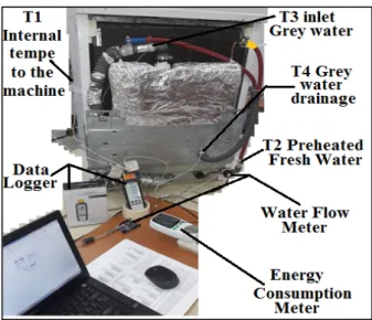
Figure 4.4. The experimentation setup and its components. The figure 4.4 shows the experimentation setup and its components that are:
• Computer
• Energy consumption meter • Water flow meter
• Dishwasher
• Greywater drainage (outlet from heat exchanger) • Water outlet from heat exchanger (inlet to dishwasher) • Water inlet to heat exchanger (cold tap water)
• Greywater inlet to heat exchanger (outlet of machine) • Heat exchanger
23
Figure 4.5. The temperature reading points on the experimentation setup. The Figure 4.5 shows the temperature reading points on the experimentation setup.
• T1 (Internal temperature to the machine)
• T2 (Inlet tap water to the dishwasher from the exit of heat exchanger) • T3 (Greywater inlet to heat exchanger from dishwasher)
• T4 (Greywater drainage to main drain)
Four points were taken to read the temperature in the experiment to compare them in each wash cycle and each stage in each wash cycle (T1, T2, T3 and T4). The tap water temperature was measured separately before the experimentations and was determined about 20 oC. We have determined and compared the heat recovery performance of the
two different heat exchanger attachments to the dishwasher. The dishwasher energy consumption and saving capability by the heat exchangers attachment were compared for fully load and unloaded conditions of the dishwasher.
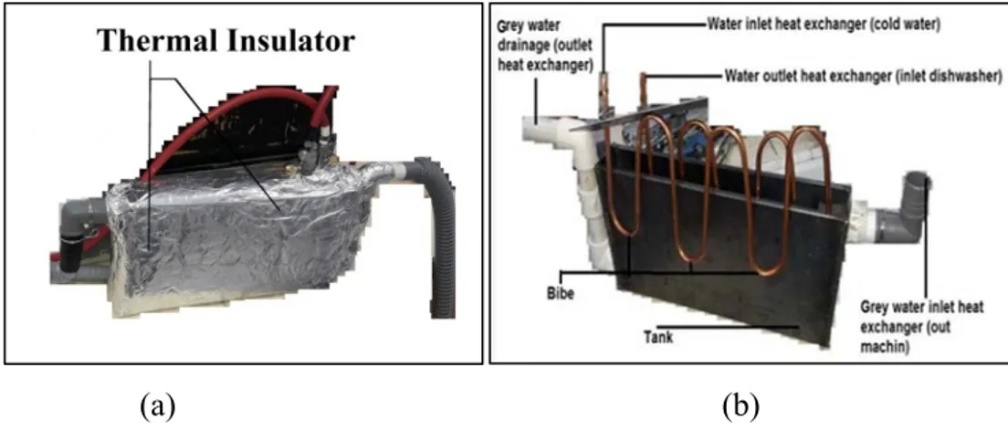
The specifications of the shell and tube heat exchanger can be defined as below: • Length of pipe of small heat exchanger: 2.60 m
• Size of tank of small heat exchanger: 40.5 cm x 21 cm x 6.5 cm • Capacity of shell side: 5.350 L
24
Figure 4.6 (a, b) presents the shell and tube heat exchanger with and without isolation. The components of shell and tube heat exchanger as can be seen in Figure 4.6 (b), are as follow:
• Tank • Pipe
• Greywater inlet to the heat exchanger from dishwasher • Water outlet from heat exchanger to in the dishwasher • Water inlet to heat exchanger from the tap
• Greywater outlet from heat exchanger to main drain.
(a) (b)
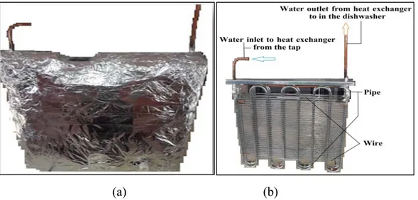
Figure 4.6. The shell and tube heat exchanger with (a) and without (b) heat isolation. The specifications of shell and wire on tube heat exchanger can be summarized as:
• Length of pipe of big heat exchanger: 10.80 m
• Size of tank of big heat exchanger: 45 cm * 40 cm * 5 cm • Capacity of tank of big heat exchanger: 7.200 L
• Surface Area of big heat exchanger: 0.271 m2
Figure 4.7 (a, b) presents the shell and wire on tube heat exchanger with and heat isolation.
The components of shell and wire on tube heat exchanger as can be seen in Figure 4.7 (b), are as follow:
25 • Tank
• Pipe
• Greywater inlet to the heat exchanger from the dishwasher • Water outlet from heat exchanger to inlet dishwasher
(a) (b)
Figure 4.7. The shell and wire on tube heat exchanger with (a) and without (b) heat isolation.
26
PART 5
RESULTS AND DISCUSSION
In this section we assessed the measured data by the attachment of two different type of the heat exchanger to the dishwasher. The black curves on the graphs designates the temperature inside the dishwasher (T1). Red curves show the temperature of the preheated water in the heat exchanger and enters to dishwasher (T2). Blue curves present the temperature of the greywater leaves from the dishwasher and fills into the heat exchanger (T3). Green curves present the temperature of the greywater discharging from heat exchanger to main drain line (T4). The time is given in the horizontal axis of the graphs and the temperature data were shared in the vertical axis of the graphs.
5.1. EXAMINING THE ECONOMY PROGRAM FOR THE CASE THAT THE DISHWASHER IS UNLOADED
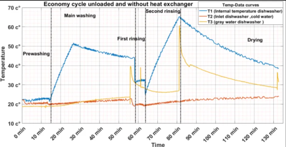
The Figure 5.1 present the measured temperature data of the dishwasher without heat exchanger attachment and for unloaded condition of dishwasher.
Figure 5.1. Temperature variation during the economy cycle in unloaded case of dishwasher without heat exchanger attachment.
27
The full time of cycle takes approximately about 135 minutes. The economy cycle also composts of prewashing, main washing, first and second rinsing and lastly drying subprocess in the order. The average water temperature for prewashing is approximately 21.8 oC. The prewashing process also takes about 15 minutes. At the
end of prewash, the water is discharged and dishwasher refills from tap to do main washing. Then, the main washing process occurs with the average water temperature is approximately about 46.6 oC and the process takes about 43 minutes. By the
completion of main washing, the water discharged again, and the dishwasher refilled with tap water. The first rinsing process completes about in 5 minutes and the water discharged from dishwasher at an average temperature about 32.5 oC. By the refilling
of the dishwasher, the second rinsing starts and takes about 18 minutes. The average water temperature is approximately about 48 oC during the second rinsing process. The
cycle completes with the drying process and it takes about 54 minutes. The total energy consumption of the dishwasher was measured about 0.872 kWh.
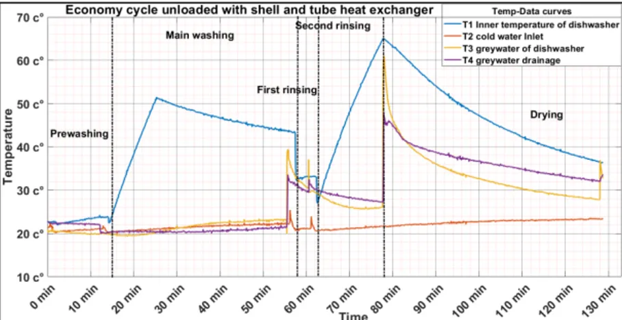
The Figure 5.2 shows the measured temperature data of experimentation process of the dishwasher for the economy cycle unloaded case with the attachment of shell and tube heat exchanger.
Figure 5.2. Temperature variation during economy cycle in unloaded case of dishwasher with shell and tube heat exchanger.
The total cycle time is approximately about 133 minutes. The prewashing period occurs approximately at 12.8 oC and completes in 15 minutes. The discharge water of
28
oC. The main washing takes about 43 minutes at an average temperature of 45.5 oC.
By the completion of the main washing the discharge water heats the refill water 24.7
oC in the heat exchanger during the refilling process. The first rinsing process takes
about 5 minutes and with the average temperature of 33.5 oC, the second rinsing starts
and takes about 15 minutes. The average water temperature is approximately about 48
oC during the second rinsing process. The cycle completes with the drying process and
it takes about 55 minutes. As the amount of electricity consumption in this cycle is 0.859 kWh. Energy consumption of dishwasher is decreased about 1.49% by recovering energy with shell and tube heat exchanger.
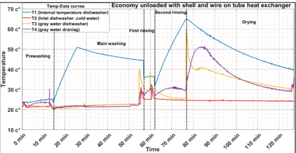
Figure 5.3 shows the economy cycle unloaded case of the dishwasher with attached shell and wire on tube heat exchanger.
Figure 5.3. Temperature variation during economy cycle in unloaded case of dishwasher with shell and wire on tube heat exchanger.
The Figure 5.3 shows the measured temperature data of experimentation process of the dishwasher for the economy cycle unloaded case with the attachment of shell and wire on tube heat exchanger. The total cycle time is approximately about 127 minutes. The prewashing period occurs approximately at 22 oC and completes in 15 minutes.
The main washing takes about 42 minutes at an average temperature of 40.5 oC. By
the completion of the main washing the discharge water come together with the refill water in the heat exchanger and some of the heat that is recovered to refill tap water. The refill water is preheated to 27 oC. The first rinsing process takes about 5 minutes
29
and with the average temperature of 36 oC, the second rinsing starts and takes about
15 minutes. The first rinsing discharge water heats the refill water to 24 oC. The
average water temperature is approximately about 52 oC during the second rinsing
process. The cycle completes with the drying process and it takes about 50 minutes. Total amount of electricity consumption in this cycle is 0.758 kWh. Energy consumption of dishwasher is decreased about 13.1% by recovering energy with shell and tube heat exchanger.
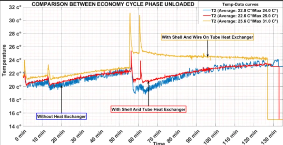
Preheated water temperatures by the recovery of heat from dishwasher greywater with the heat exchangers were compared to each other in Figure 5.4 for unloaded case of dishwasher and economy program.
Figure 5.4. Comparison of the temperature of the water entering the dishwasher in the economy program unloaded.
We noticed from the Figure 5.4 the followings: the blue curve, which represents the temperature of the tap water in the economy cycle without attachment of the heat exchanger, where the average preheated water temperature is approximately 21.60 oC.
The red curve after installing the shell and tube heat exchanger and the average temperature reached 21.86 oC with a rate of 1.20% Yellow curve after installing the
shell and wire on tube heat exchanger, the average temperature reached approximately 23.51 oC, with increase of 8.85%.
Table 5.1 shows the energy consumption of the dishwasher for unloaded case of the dishwasher for the economy cycle.
30
Table 5.1. The energy consumption of the dishwasher for unloaded case and the economy cycle. T ype of heat exchanger Quantity of water (L) Total time of cycle (min) Temperature of tap water (°C) Environment temperature (°C) Surface area of heat exchanger (m²) Energy consumption per dishwasher without heat exchanger (kWh) Energy consumption per dishwasher with heat exchanger (kWh) Percentage reduction in energy [%] Without heat exchanger 16.501 135 20 19 - 20 - 0.872 -
Shell and tube
16.485 133 20.5 19 - 20 0.065 - 0.859 1.49 Shell and wir e on tube 15.471 127 20.5 19 - 20 0.271 - 0.758 13.1
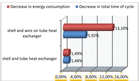
Figure 5.5 shows the rate of reductions in energy, and time consumption by the attachment of heat exchangers in the unloaded case of dishwasher in the economy program.
Figure 5.5. The rate of reduction in energy, and time consumption by the attachment of the heat exchangers to dishwasher in unloaded case and economy cycle. The rate of reduction in energy, and time consumption by the attachment of the heat exchangers to dishwasher in unloaded case and economy cycle. The rate of energy
0,00% 4,00% 8,00% 12,00% 16,00% shell and tube heat exchanger
shell and wire on tube heat exchanger
1,48%
5,92%
1,49%
13,10%