IET Power Electronics
Research Article
High-efficiency flow-through induction
heating
ISSN 1755-4535 Received on 6th January 2020 Accepted on 31st March 2020 E-First on 1st May 2020 doi: 10.1049/iet-pel.2019.1609 www.ietdl.orgVeli Tayfun Kilic
1, Emre Unal
2, Hilmi Volkan Demir
2,3,41Department of Electrical and Electronics Engineering, Abdullah Gul University, Kayseri, Turkey 2Institute of Materials Science and Nanotechnology, Bilkent University, Ankara, Turkey
3Department of Electrical and Electronics Engineering, Department of Physics, Bilkent University, Ankara, Turkey
4School of Electrical and Electronic Engineering, School of Physical and Mathematical Sciences, Nanyang Technological University, Singapore E-mail: [email protected]
Abstract: This study reports a newly designed induction heating system for efficient, fast, and safe flow-through heating. The
system has a very simple architecture, which is composed of a transmitting coil, an isolating plastic pipe, and an embedded metal shell. Wireless energy transfer from the external coil to the internal metal shell through the pipe is essential for decreasing losses. Also, a large contact surface between a fluid and the immersed shell enables rapid heat transfer. The proposed heating system was systematically investigated for different shell geometries and the results were compared with a commercially available conductive flow-through heating device. As a proof-of-concept demonstration, a prototype of the designed induction heating system was manufactured and the heating measurements were conducted with water. Power transfer efficiency of the prototyped induction heating system was measured to be 97%. The comparative study indicates that such high-efficiency induction flow-through heating system offers a great potential for replacing the conventional conductive heating device used in household applications in which the rapid and compact heating is desired.
1 Introduction
With the development of high-frequency inverter topologies the induction systems have been increasingly becoming more popular. Due to their great advantages including safety, cleanliness, high speed, high efficiency, and good controllability, the induction systems are commonly used in various areas including heating [1– 5] and wireless power transfer [6, 7]. Induction-based wireless power transfer is mostly utilised in autonomous electronic devices for charging purpose. On the other hand, induction-based heating systems have different industrial and domestic applications like metal melting and forming, and induction ovens.
Generating hot water is another important application for induction heating systems. Hot water is used quite often in household goods such as in dishwashers, washing machines, steam irons, kettles, and coffeemakers; and its production demands a considerable amount of power. As a consequence of its process and design simplicities, the hot water production is achieved with conductive heating in most commercial applications. However, environmental and material losses, i.e. heat spread due to conduction and convection together with infrared (IR) radiation, limit the efficiency of the conventional conduction heaters. Also, it is necessary to take precautions against heating parts of the instrument that are unwanted to be heated to a high temperature which may harm the users, because the generated heat energy can be transferred conductively not only to the target fluid but also to other contact parts of the instrument. Immersing heater into the fluid is one possible way to overcome contact losses and decrease IR radiation. However, this method is neither useful nor safe if electric power leaks into the water for conventional conductive heaters. On the other hand, in the induction heating process, without any electric power leakage problem because of the nature of wireless power transmission, it is, in principle, possible to minimise environmental and material thermal losses.
In induction fluid heating, two classes of methods are used. In the first category, fluid is gathered in a chamber or tank where it is heated up inductively [8, 9]. However, in this process the fluid flow rate decreases and additional energy is required for pumping. In the second class, on the other hand, fluid is heated inductively while flowing. By this way, fluid's continuous flow at a constant rate is
achieved. In addition, possibly by supplying dense magnetic energy, high-energy transfer rate and high efficiency can be obtained in tankless heating systems.
In the literature, there are previous reports about tankless fluid induction heating. In some of these studies heating was achieved by induction heating of metal and/or ferromagnetic pipe in which the fluid flows [10, 11]. However, in this case, since the fluid is in contact with the pipe from only its inner wall, achieving the uniform fluid heating is not possible. Also, environmental heat losses from the pipe's outer wall dramatically degrade the system efficiency. In other studies, as another approach, induction heating is achieved with the help of metal heater immersed in a fluid [12– 24]. In such systems non-metallic pipe, coil, and heat exchanger, i.e. metal heater, are placed. Since the pipe is non-metallic and the heat exchanger is immersed into the fluid, the heat loss is caused only by the heating of the coil due to the self-resistance and the current passing through it. Resistance variations of such wire windings have been previously studied in the literature [25, 26]. In the reported systems, different types of heat exchanger have been investigated. These include cylindrical and spiral heater structures with involuted shapes towards the centre [12–17], carbon ceramic heaters that consist of many thin axial tubes [15–18], heaters with metal layer structure [17–21], and heaters with an iron core rod stick at the centre and foamed metals with ring shapes placed around the stick [22]. Although these structures provide high contact surface and uniform heating, they are complex and not suitable for mass production. Also, the heater with an iron core rod stick at its centre and ring shape foamed metals around the stick might decrease the fluid's flow rate [22]. Heaters with unusual geometries such as cork screw and star shapes were also reported [23, 24]. However, these structures are complex for low-cost manufacturing. Also, these are not optimum for inducing large continuous eddy current. To induce a strong eddy current, the heater geometry needs to be continuous and has the same orientation with that of the coil.
In this paper, we propose and demonstrate a newly designed simple induction flow-through heating system. In the proposed system, water in an isolating plastic pipe is heated up by a metal heater with cylindrical shell geometry. Different than the previous reports, this architecture uniquely combines the first and second
arrangements of the flow-through heaters into a simple structure where the flowing fluid is kept inside the electrically and thermally non-conductive pipe with an embedded metal shell having fluid flow in both its inside and outside. Therefore, the shell heater allows for heat transfer from the fully immersed shell, while being inductively driven by the coil external to the pipe and in perfect alignment with the shell. This simplicity allows for efficient and rapid heating while keeping the low-cost heater. Here heating of the proposed architecture has been examined systematically with three-dimensional (3D) numerical simulations for various heater dimensions. Also, a device was manufactured for a proof-of-concept demonstration. Heating speed of the device was experimentally measured. Besides the proposed induction heating system having a very simple architecture, it is found to be very efficient and rapid, and addresses the aforementioned fluid heating system problems.
2 Numerical study
2.1 Conventional conductive pipe heating system
Our analysis is done with a conductive heating system that is used in a commercial dishwasher. The system is shown in Fig. 1. Here there exist a metal pipe and a metal wire wound around the pipe. Heating of the flowing water inside the pipe is achieved with conduction heat transfer from the metal winding to the water
through the pipe. The system was numerically simulated with 3D electromagnetic and thermal solver based on its real dimensions. In the simulations, the system was first modelled in 3D and electromagnetic fields and related quantities such as electrical currents and ohmic power losses were calculated at each mesh point over the system. After calculating electromagnetic fields and related quantities, these results were implemented in the thermal solver. Since electrical and magnetic fields are calculated and electrical and magnetic properties of system parts such as electrical permittivity, magnetic permeability, electrical resistivity etc. are known together with material properties including thermal conductivity, heat capacity, material density, and so on, in thermal solver by using these data arisen heat energies over the system and radiation of these energies between the system parts and environment are calculated. The modelled system structure is shown in Figs. 2a–c.
In these figures, pipe, water, and copper wire are represented with grey, blue, and yellow colours, respectively. The pipe has a cylindrical shape with 0.8 mm wall thickness and 145 mm axis length. The copper wire is wound around the pipe such that it has 5.65 mm radius and six turns covering part of the pipe surface with ∼80 mm length and water fills the pipe completely. Although, in reality, water is flowing, in our simulations we modelled water as a static medium. In addition, in simulations the state changes and hysteresis of the water and the other materials are ignored for easy understanding of the system behaviour. Otherwise, if the state changes and hysteresis of the materials are not ignored then changes in material properties with temperature and state variations should be considered, which makes the analysis complex.
The system was analysed both electromagnetically and thermally. It is seen that all the input power is dissipated in the copper wire as an ohmic loss. Since measured power dissipation in the system was ∼1800 W, in our simulations we first set the total dissipated power in the system to be equal with the real system. However, in these simulations water temperature was calculated to exceed 100°C very quickly. Although in reality water boils over 100°C, in simulations water temperature can exceed 100°C because of ignoring state changes of the materials. Therefore, we repeated our simulations with total dissipated power in the system to be equal to 50 W. In this paper, for a more fair comparison with the measurement results, simulation results with 50 W power dissipation in the system are given. Fig. 2d shows the temperature distribution of the modelled system for 200 s after the power is turned on.
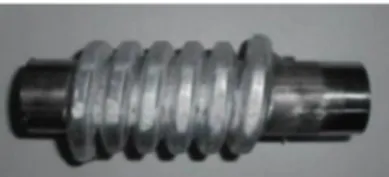
Additionally, the temperature distribution on a constant cross-sectional y plane in Fig. 2d, which passes through the centre of the system, is illustrated in Fig. 3a. In this figure, black lines are drawn to indicate the end points of the pipe.
In Figs. 3a and 2d copper wire's heating to high-temperature levels is seen. This heat is conductively transferred to the pipe and then to the water. On the other hand, there is heat spread to the environment, too, but this is a loss of energy, which decreases the system efficiency. In these figures, the non-uniform heating of the water is also observed. As expected, water heats up starting from the sides in contact with the metal pipe. In Fig. 3b the temperature distribution of the system along the line at the constant z = 40 mm in Fig. 3a, which passes almost through the middle of the system, is shown for various time instants. In this figure, the metal pipe's wall is pointed out with additional grids at x = ±15.25 mm and ±16.05 mm. Also, to clearly indicate its thickness, intervals between the grids are filled with black colour in the upper side of the figure. It is seen that the water temperature near the metal pipe at t = 200 s is around 45°C.
2.2 Proposed induction pipe heating system
Next, we investigated a newly designed induction heating system using systematic 3D numerical simulations. As in conventional conductive pipe heating system simulations, the proposed induction heating system was first modelled and then analysed with electromagnetic and thermal solvers. The modelled system structure is shown in Fig. 4. In the designed system, the metal pipe is replaced with a non-magnetic, thermally isolating, and
high-Fig. 1 Exemplary conductive pipe heating system in a commercial dishwasher
Fig. 2 Modelled conductive heating system with its parts and temperature distribution of it
(a)–(c) Side, perspective, and top views of the modelled system and its parts, (d)
temperature tolerant material. One of such pipes that have these features and are commercially available is a plastic pipe, which consists of three layers. The middle layer comprises fibreglass and is sandwiched between two polypropylene random (PPR) copolymer (Type3) films. The fibreglass and PPR layers are represented in cyan and claret red colours in Fig. 4c. In addition, in our new system, the cylindrical metal shell is immersed in the water. Here we used stainless steel (AISI 420) for the shell material because of its high magnetic permeability and stiffness together with its robustness against corrosion and material deformations. The immersed shell is illustrated in grey in Figs. 4b and c. As seen in this figure, only the inner PPR layer of the plastic pipe and the metal shell are in contact with the water. Therefore, the proposed system is highly resistant to corrosion and material deformations such as rust formations.
Furthermore, in the designed system, coil winding with a smaller radius and higher turn number, i.e. with a radius of 1.5 mm and 23 turns, is used. For a fair comparison, we wound the coil in the designed system to cover the part of the plastic pipe having the same length with the part of the metal pipe covered by the winding wire in the conductive heating system. The coil turn number was optimised with simulations. As the turn number increases, the magnetic field density and coupling between the coil and the metal shell enhance. In the proposed induction pipe heating system coupling between the coil and the immersed metal shell through generated magnetic flux is essential for high efficiency. However, the self-resistance of the coil increases, too, as a result of an increase in the coil's length and decrease in its cross-sectional area. During coil's optimisation input current magnitude required for 1800 W power dissipation in the system and current capacity of the wire are other issues taken into account. The coil used in the designed system is thick enough to carry the current required for 1800 W power dissipation in the system.
The designed system was studied for various metal shell dimensions. We initially set the metal shell's inner radius to 5.25 mm. Without changing the shell's inner radius, numerical simulations were repeated for three wall thicknesses that are 2, 4, and 6 mm. The immersed metal shell in the modelled heating system that is shown in Figs. 4b and c has 5.25 mm inner radius and 2 mm wall thickness.
For fair comparisons, in simulations the total dissipated powers in all systems are determined to be 50 W at 50 kHz operational frequency common for induction systems. It is observed that most of the supplied power is transferred to and dissipated on the metal shell as an ohmic loss. Since the metal shell is immersed into water, almost all of the power that turns into heat in the shell is thus transferred to the water.
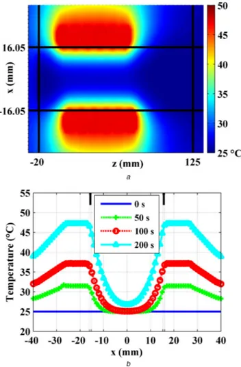
Similar to the conductive system, the temperature distribution of the designed systems on a constant y plane, which passes through the midpoint of the systems, is presented in Figs. 5a–c. As in Fig. 3a, here, black lines are drawn to indicate the end points of the plastic pipe. Also, for fair comparisons with the conductive pipe heating system (see Fig. 3a) and easy detection of water heating, the minimum and maximum colour bar limits in the temperature distribution maps are set to be 25 and 100°C, respectively. The maximum limit of 100°C enables us to clearly see that the water is not boiling. In these figures, increased heat conduction from the metal shell to the water is observed. In addition, power loss to the environment is much smaller than that obtained in the conductive heating system. Since the metal pipe is replaced with the thermally isolating plastic pipe, the heat energy spreading to the environment as a loss occurs only from the copper coil. The lost power is found to be 7–10% of the input power.
Temperature increase over the coil due to lost power in the modelled induction pipe heating systems is very low. In these figures, it is represented with dark blue colours in areas just above and just below the black lines at x = 20.50−20.50 mm, respectively, indicating end points of the plastic pipe. Since heat energy arisen on the coil as a result of its self-heating is very low, unlike the conductive heating system, in the modelled induction pipe heating systems very small energy is transferred to the medium around the
Fig. 3 Temperature distribution of the modelled conductive heating system
(a) On constant plane that passes through the middle of the system at t = 200 s, (b) On
a constant line through the middle point at various time instants
Fig. 4 Modelled new induction pipe heating system with metal shell having 5.25 mm inner radius and 2 mm wall thickness, where system parts and materials are indicated with colour labels and pointed out with lines for grey scale view
coil and materials in contact with it. Therefore, in these figures, the dark blue colours continue in the x- and z-direction. It is calculated that the temperature of the coil at t = 200 s reaches to 27.3, 26.9, and 26.6°C in the systems, where metal shell thicknesses are 2, 4, and 6 mm, respectively. These temperatures are much lower than the temperature of copper wire reaches at t = 200 s in the conventional conductive heating system, which is around 47.2°C (see Fig. 3b). As expected, the relationship between the highest temperature values of the coil in the systems is the same with the relationship between ohmic power losses in the coil (see Table 1), such that the temperature that coil reaches and the ohmic power loss in the coil are found to be highest for the system in which the metal shell with 2 mm wall thickness is used. Similarly, the temperature that the coil reaches and the power loss in the coil are calculated to be lowest in the system in which the metal shell with 6 mm wall thickness is placed.
Furthermore, in these figures it is also clear that the temperature distribution of the water is more uniform than that obtained before with conductive heating system. Since the water is in contact with
the metal shell from its inner and outer surfaces, more uniform and quicker heating is achieved.
In Fig. 5d the temperature of the systems along a constant line through the middle of the system and at the intersection of constant
y and constant z planes at t = 200 s is shown. In this figure, the
walls of the immersed shell are marked with black lines. The metal shell reaches higher temperatures when its wall becomes thinner. This is expected because in the simulations it is seen that the percentage of the input power coupled to and dissipated in the shell does not change too much with its wall thickness. Resultantly, the same amount of power increases the temperature of the thin metal shell more with respect to the thick metal shell. In addition, because of the high metal shell temperature, water inside the thin shell heats more. However, a decrease in the temperature of the water outside the metal shell is faster in the case that a thin shell is used. This is due to the large water mass outside the shell.
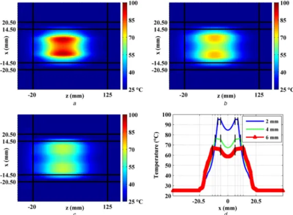
We further studied the system with a metal shell having a 7.25 mm inner radius. Simulations were repeated with metal shells having different wall thicknesses. In simulations, again the total dissipated power in the systems is set to 50 W at 50 kHz frequency. Temperature map of the systems on the constant y plane that passes through the midpoint of the systems 200 s after the power is on is shown in Figs. 6a and b. Similar observations within Figs. 5a–c are done here. Also, in Fig. 6c the temperature of the systems at t = 200 s on constant line that passes through the middle of the systems is shown. Again, immersed shell walls are pointed out with black lines.
In Fig. 6c metal shells reach to lower temperatures than shells having the same wall thicknesses in Fig. 5d. This is because of the mass of the metal shell, which is proportional to shell's inner radius. However, the low temperature of the shell causes a decrease in heating speed of the fluid because the conduction heat transfer rate from metal shell to the water is proportional with the temperature gradient between them. In addition, the plastic pipe's temperature is higher in Fig. 6c than that seen in Fig. 5d. This is expected because as shell's radius increases, it gets closer to the pipe and water volume between the pipe and the metal shell decreases. However, heating of the pipe is unwanted and causes loss in the system.
Fig. 5 Temperature profile of the modelled induction pipe heating systems with metal shell having 5.25 mm inner radius at t = 200 s
(a)–(c) On constant plane that passes through the middle of the system, where metal shell wall thicknesses are 2, 4, and 6 mm, respectively, (d) Along a constant line through the
middle of the system
Table 1 Power losses and transferred power in systems
Inner radius, mm Wall thickness, mm Total dissipated power, W Ohmic power loss in wire, W Transferred power to metal shell, W 5.25 2 50 (100%) 5.14 (10.28%) 44.86 (89.72%) 4 50 (100%) 4.12 (8.24%) 45.88 (91.76%) 6 50 (100%) 3.29 (6.58%) 46.71 (93.42%) 7.25 2 50 (100%) 3.99 (7.98%) 46.01 (92.02%) 4 50 (100%) 3.27 (6.54%) 46.73 (93.46%) 9.25 2 50 (100%) 3.25 (6.50%) 46.75 (93.50%) 4 50 (100%) 2.85 (5.70%) 47.15 (94.30%)
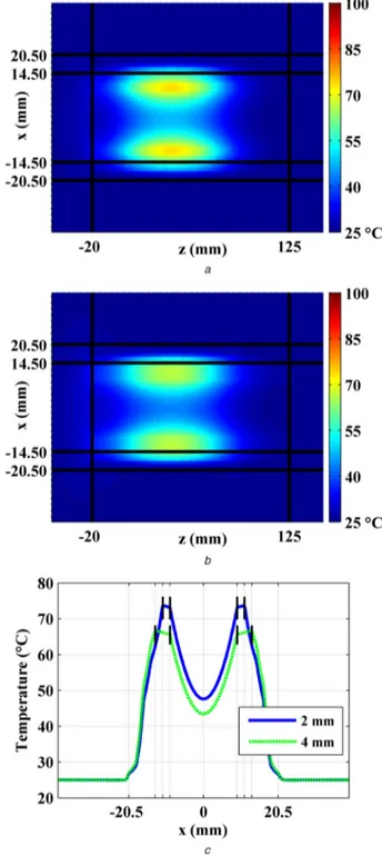
Lastly, a system with an immersed metal shell having an inner radius of 9.25 mm was examined for two different wall thicknesses. As in previous simulations, total dissipated powers in the systems are calculated to be 50 W at 50 kHz frequency. The temperature distribution of the new systems at t = 200 s on the constant y plane that passes through the middle of the systems is shown in Figs. 7a and b.
In these figures it is seen that the system cannot heat water around the centre to temperature levels obtained in previous cases. This is because of the existing large water mass inside the metal shell. On the other hand, now less water occupies the volume between the pipe and the metal shell. Therefore, water in this
volume is heated up more but this causes more heating of the pipe and so larger loss. These observations are also made in Fig. 7c. In this figure, the temperature of the systems at t = 200 s on constant line, which is the intersection of constant y and constant z planes that pass through the centre of the system, is shown.
Note that temperature of the plastic pipe reaches up to 58° and 63° at x = ±14.50 mm points, where the pipe and the water are in contact, in systems in which 2 and 4 mm thick metal shells are used, respectively. These values are higher than those obtained previously. However, the temperature of the water around the centre is lower than 50°C, which is below the water temperatures at the system's centre reached in previous systems.
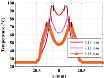
For further comparisons, the temperature profile of the designed systems with metal shells having the same 2 mm thickness but different inner radii, i.e. 5.25, 7.25, and 9.25 mm, along the
Fig. 6 Temperature profile of the modelled induction pipe heating systems with metal shell having 7.25 mm inner radius at t = 200 s
(a), (b) On constant plane that passes through the middle of the systems, where metal
shell wall thicknesses are 2 and 4 mm, respectively, (c) On constant line through the midpoint
Fig. 7 Temperature profile of the modelled induction pipe heating systems with metal shell having 9.25 mm inner radius at t = 200 s
(a), (b) On constant plane that passes through the middle of the systems, where metal
shell wall thicknesses are 2 and 4 mm, respectively, (c) On constant line through the midpoint
constant line, which passes through the middle of the systems, at the intersection of constant y and constant z planes at t = 200 s is shown in Fig. 8. As in previous figures (Figs. 5d, 6c, and 7c), here, black lines indicate the walls of the immersed shell in the systems.
In this figure, as expected, the shell temperature reaches to higher values as the shell's inner radius becomes smaller. Since transferred power to metal shell in the systems is almost constant, the same power heats up the shell more if its mass, which is proportional with its radius for constant thickness, is small. Also, in this figure temperature of the water inside the shell is higher for the shell having a small radius. This is because of the high temperature of the shell and decreased water volume inside it. On the other hand, the temperature of the water between the shell and the pipe increases with the shell radius. Since the shell and the pipe become
closer as the shell radius increases, less water occupies the volume between the shell and the pipe, which results in high water temperature outside the shell.
As seen in these figures (Figs. 5d, 6c, 7c, and 8), heating of water inside the system depends not only on the ratio of the power transferred from coil to the metal shell but also on other parameters including the inner radius and wall thickness of the shell. The temperature that metal shell reaches increases as the shell's inner radius and thickness decreases, which results in the high-temperature gradient between the shell and the water and thus rapid heat transfer. Therefore, for system applications in which the fluid flow rate is high, it is preferred to use a thin metal shell that allows for quick heat transfer from the metal shell to the water while having a power transfer ratio similar to that obtained with a thick metal shell. On the other hand, for system applications in which the fluid flow rate is low or fluid circulates through our designed induction pipe heating system and is heated up continuously it is better to place a thick metal shell.
In Table 1 calculated power losses and transferred power in the systems are given. It is seen that for all the cases coupling between the metal shell and the coil is large. Therefore, in the designed system most of the supplied power, i.e. ≥90% of the supplied power, is transferred to and dissipated on the metal shell as an ohmic loss.
In this table, the percentage value of transferred power to the metal shell increases with both its inner radius and wall thickness but this increase is not too high.
3 Measurements
As proof of demonstration, we have manufactured a prototype of induction pipe heating device and had experimented with static water. The photo of the prototype is given in Fig. 9.
The prototype consists of copper winding wire, plastic pipe, and a metal shell from outside to inside. Their geometric parameters are the same as those we set in our simulations. However, to decrease the ohmic power loss in the winding further, the coil is made of several litz wires. In addition, different from our simulations, plastic holders are located between the metal shell and the plastic pipe. Since their volumes are too small and they are made of non-magnetic materials, these plastic holders do not affect the heating of water inside the pipe.
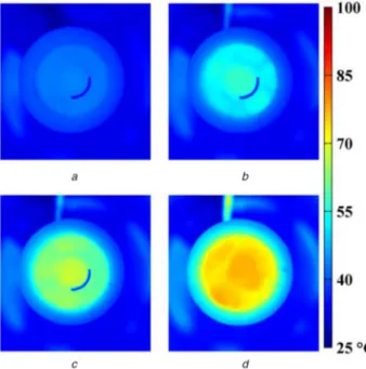
We have investigated the manufactured device with heating measurements. The schematic view of the experimental setup is shown in Fig. 10. In the measurement setup, the designed prototype is connected to an ac power supply. Again, similar within our simulations, the plastic pipe is filled with water and the metal shell is immersed into the water. Water is static and has ∼78,600 mm3 volume. Also, as in simulations, here real supplied power was set around 50 W at 50 kHz frequency. Images captured by a thermal camera from the top side at various time instants are shown in Fig. 11.
In this figure, the uniform heating of the water is clearly seen. In subfigures a, b, and c the blue coloured arc is to prevent IR reflections from the metal and to identify the shell we stuck a thermal resistant Kapton tape on the part of the metal shell. In addition, the heat loss occurred from the heating coil to the environment is observed to be considerably small with respect to conductive heating systems. As seen, in subfigure d the pipe temperature is around 50°C while the water inside it has a temperature of ∼75°C. These results were expected and deduced before in our simulations. In Fig. 12 water temperature increase with time is presented for two points that are inside and outside the metal shell. These points are marked with blue and black dots in the inset having harmony with plots.
The energy that is transferred to and heats up the water is calculated by using (1):
Q = d × V × C × ΔT (1)
here d and C are the material density (1 × 10⁻⁶ kg/mm3) and the specific heat (4181 J/kg/°C) of the water. Also, V is the volume (19,000 mm3 inside the metal shell and 59,600 mm3 outside the
Fig. 8 Temperature profile of the modelled induction pipe heating systems with metal shell having 2 mm thickness and different inner radii of 5.25, 7.25, and 9.25 mm, on constant line through the middle of the system at t = 200 s
Fig. 9 Photo of the manufactured induction pipe heating device prototype
Fig. 10 Schematic view of experimental setup for static water induction heating measurement
shell) of the water and ΔT is the temperature change (33.5°C for the water inside the shell and 31.1°C for the water outside the shell). It is found that 10,411 J energy was transferred to the water and increased its temperature. Since 50 W power was supplied over 214 s on average, the energy that is transferred to and heats up the water is found to be 97% (10,411/(50 × 214)) of the total real energy supplied to the system, which is very close to the percentage values given in Table 1. In addition to fluctuations in the supplied power, the energy dissipated for the shell's temperature increases and the additional energy required for state change during water's evaporation together with winding the coils as several litz strands play a role in having a very small difference between the percentage values of the transferred power to metal shell calculated in simulations and the measured result.
4 Conclusion
In this paper, a newly designed induction pipe heating system is presented. With 3D numerical simulations and measurements, the energy transfer efficiency and heating speed of the designed system are investigated and results are compared with those of a conductive heating system exists in commercial dishwashers. It is shown that the designed induction heating system is very efficient in spite of its easy architecture. The power loss in the designed system is found to be smaller than that observed in the conductive
heating system. In simulations the percentage of the input power transferred to the water in the designed system is calculated to achieve 94% and in measurement it is found as 97%. Also, with simulations it is demonstrated that the power transfer efficiency in the designed heating system is almost independent of the immersed metal shell's dimensions.
Another advantage of the designed induction heating system is uniform fluid heating. Uniform heating of the system is demonstrated with both simulations and measurement. Furthermore, while heating, the ambient temperature of the designed system is found to be lower than that of the conductive heater, which makes the designed induction heating system safer for users. The findings of this study are beneficial for applications that require fast and efficient fluid heating. The current extension of this work focuses on the design of a commercial household appliance on which the induction flow-through heating system is used.
5 Acknowledgments
The authors would like to thank Berkay Bozok for his assistance in further characterisation in a dishwasher at a later stage as part of Arcelik A.S. project.
6 References
[1] Lupi, S., Forzan, M., Aliferov, A.: ‘Induction and direct resistance heating’ (Springer International Publishing, Switzerland, 2015, 1st edn.)
[2] Rudnev, V., Loveless, D., Cook, R.L.: ‘Handbook of induction heating’ (CRC Press, USA., 2003, 2nd edn.)
[3] Lucia, O., Acero, J., Carretero, C., et al.: ‘Induction heating appliances: toward more flexible cooking surfaces’, IEEE Ind. Electron. Mag., 2013, 7, (3), pp. 35–47
[4] Acero, J., Burdio, J.M., Barragan, L.A., et al.: ‘Domestic induction appliances’, IEEE Ind. Appl. Mag., 2010, 16, (2), pp. 39–47
[5] Alwash, J.H.H., Sultan, S.K.: ‘Performance prediction of single-sided induction heating system’, IEEE Trans. Energy Convers., 2010, 25, (4), pp. 1057–1062
[6] Agbinya, J.I.: ‘Wireless power transfer’ (River Publishers, Denmark, 2012, 2nd edn.)
[7] Kurs, A., Karalis, A., Moffatt, R., et al.: ‘Wireless power transfer via strongly coupled magnetic resonances’, Science, 2007, 317, (5834), pp. 83–86 [8] Uemura, M.: ‘Induction fluid heating system’. U.S. Patent Application
0153369 A1, October 2002
[9] Sung, H.J., Han, D.S., Kwon, Y.H., et al.: ‘Steam generation apparatus using induction heating and oven including the same’. U.S. Patent 7326891 B2, February 2008
[10] Engler, H.-W., Buser, J.: ‘Washing appliance with induction heating’. European Patent EP 2100996 B1, February 2016
[11] Skoczkowski, T.P., Kalus, M.F.: ‘The mathematical model of induction heating of ferromagnetic pipes’, IEEE Trans. Magn., 1989, 25, (3), pp. 2745– 2750
[12] Terai, H., Sadakata, H., Omori, H., et al.: ‘High frequency soft switching inverter for fluid-heating appliance using induction eddy current-based involuted type heat exchanger’. Proc. IEEE Power Electronics and Specialists Conf., Cairns, Qld., Australia, June 2002, pp. 1874–1878
[13] Ahmed, N.A.: ‘High-frequency soft-switching AC conversion circuit with dual-mode PWM/PDM control strategy for high-power IH applications’, IEEE Trans. Ind. Electron., 2011, 58, (4), pp. 1440–1448
[14] Sugimura, H., Ahmed, T., Orabi, M., et al.: ‘Commercial utility frequency AC to high frequency AC soft switching power conversion circuit with non smoothing DC link for IH dual packs heater’. Proc. IEEE Conf. Industrial Electronics Society (IECON ‘04), Busan, Republic of Korea, November 2004, pp. 1155–1160
[15] Sugai, T., Ogiwara, H., Itoi, M., et al.: ‘SEPP-ZVS high frequency inverter for induction heating using B-SIT with extremely low on-resistance’. Proc. 12th Int. Power Electronics and Motion Control Conf. (EPE/PEMC ‘06), Portoroz, Slovenia, August/September 2006, pp. 705–709
[16] Kuwata, M., Ogiwara, H., Itoi, M., et al.: ‘SEPP-ZVS high frequency inverter for induction heating using newly developed SiC-SIT’. Proc. 14th Int. Power Electronics and Motion Control Conf. (EPE/PEMC ‘10), Ohrid, Macedonia, September 2010, pp. T2-1–T2-6
[17] Gamage, L., Ahmed, T., Sugimura, H., et al.: ‘Series load resonant phase shifted ZVS-PWM high-frequency inverter with a single auxiliary edge resonant AC load side snubber for induction heating super heated steamer’. Proc. 5th Int. Conf. Power Electronics and Drive System (PEDS ‘03), Singapore, Singapore, November 2003, pp. 30–37
[18] Tanaka, H., Kaneda, M., Chandhaket, S., et al.: ‘Eddy current dual packs heater based continuous pipeline fluid heating using soft switching PWM high frequency inverter’. Proc. IEEE Int. Symp. on Industrial Electronics (ISIE 2000), Cholula, Puebla, Mexico, December 2000, pp. 306–311
[19] Nakaoka, M., Kawamura, Y., Uchihori, Y.: ‘Electromagnetic induction-heated fluid energy conversion processing appliance’. U.S. Patent 5990465, November 1999
Fig. 11 Images captured by the thermal camera at various time instants
(a) t = 3 s, (b) t = 64 s, (c) t = 124 s, (d) t = 214 s
Fig. 12 Water temperature increase with time at two points that are inside (point p1) and outside (point p2) the metal shell
[20] Yamamoto, M., Iseki, T., Kajiyama, A., et al.: ‘Latest electromagnetic induction-based fluid-heating equipment using high-frequency PWM load resonant inverter’. Proc. IEEE Conf. on Power Electronics and Drive Syst.em(PEDS ‘97), Singapore, Singapore, May 1997, pp. 153–162 [21] Uchihori, Y., Kawamura, Y., Morita, S., et al.: ‘The state-of-the art
electromagnetic induction flow-through pipeline package type fluid heating appliance using series resonant PWM inverter with self-tuning PID controller-based feedback implementation’. Proc. IEEE Conf. on Industrial Automation and Control Emerging Technology Applications, Taipei, Taiwan, May 1995, pp. 14–21
[22] Sugimura, H., Kwon, S.-K., Ogiwara, H., et al.: ‘A new phase shifted ZVS-PWM controlled full bridge series resonant high frequency inverter with
auxiliary active quasi-resonant commutation circuit’. 2007 Power Conversion Conf., Nagoya, Japan, April 2007, pp. 1505–1511
[23] Self, J., Olexy, R.A., Cochran, S.: ‘Induction heater’. U.S. Patent Application 0210075 A1, September 2007
[24] Luo, S., Ding, Y.: ‘High frequency induction heating instantaneous tankless water heaters’. U.S. Patent Application 0092384 A1, April 2009
[25] Wojda, R.P., Kazimierczuk, M.K.: ‘Analytical optimization of solid-round-wire windings’, IEEE Trans. Ind. Electron., 2013, 60, (3), pp. 1033–1041 [26] Wojda, R.P., Kazimierczuk, M.K.: ‘Winding resistance of litz-wire and