REPUBLIC OF TURKEY SELCUK UNIVERSITY
GRADUATE SCHOOL OF NATURAL AND APPLIED SCIENCES
INVESTIGATION OF ELECTRICAL CONDUCTIVITY OF NANOFIBERS (PAN) CONTAINING NANOPARTICLES
(GRAPHENE, COPPER, SILICA) PRODUCED BY ELECTROSPINNING METHOD
Olivier Mukongo MPUKUTA Master of Science Thesis
Department of Mechanical Engineering
April-2018 KONYA All rights reserved
vi ABSTRACT
M.Sc. THESIS
INVESTIGATION OF ELECTRICAL CONDUCTIVITY OF NANOFIBERS (PAN) CONTAINING NANOPARTICLES (GRAPHENE, COPPER, SILICA)
PRODUCED BY ELECTROSPINNING METHOD
Olivier Mukongo MPUKUTA
THE GRADUATE SCHOOL OF NATURAL AND APPLIED SCIENCE OF SELÇUK UNIVERSITY
THE DEGREE OF MASTER OF SCIENCE IN MECHANICAL ENGINEERING
Advisor: Assoc. Prof. Dr. Kevser Dincer Co-advisor: Asst. Prof. Dr. Mehmet Okan Erdal
2018, 100 Pages Jury
Prof. Dr. Ahmet AVCI
Assoc. Prof. Dr. Kevser DINCER Assoc. Prof. Mahmut deniz YILMAZ
Prof. Dr. Ömer Sinan ŞAHIN Asst. Prof. Dr. Yusuf ÇAKMAK
In this study, the electrical conductivity of electrospun polyacrylonitrile (PAN) nanofibers containing nanoparticles (graphene, copper, silica) has been investigated as a function of the incorporated nanoparticles content and the applied voltage during the electrospinning process. Different copper, graphene and silica nanoparticles contents (1, 3 and 5 wt. %) were added separately in the electrospinning solutions consisted of PAN and dimethylformamide. In addition, the dynamic viscosity of the obtained solutions was respectively analyzed and its effects on the diameter and electrical conductivity of the as-spun fibers were investigated. Afterwards, further investigations were conducted on the samples that exhibited the highest electrical conductivity values, notably: morphology, crystalline structure, hydrophobicity of the as-spun nanofibers. Taken together, the findings suggested that fibers with low content of nanoparticles led to higher electrical conductivities. When all the results were compared to each other, the highest electrical conductivity values were obtained with 1 wt. % of copper-based fibers and the electrical conductivity values were 1.38x10⁻² S/cm and 2.83x10⁻² S/cm for nanofibers produced at 15 kV and 20 kV, respectively. In other words, compared to pure PAN nanofıbers, an increase of % 137.52 and % 1636.19 was observed in the electrical conductivity of fibers containing 1 wt. % of copper nanoparticles fabricated at 15 kV and 20 kV, respectively.
Keywords: Copper, Electrical conductivity, Electrospinning process, Electrospun nanofibers, Graphene, Hydrophobicity, Morphology, Nanoparticles, Polyacrylonitrile (PAN) nanofibers, Silica.
vii ÖZET
YÜKSEK LİSANS TEZİ
ELEKTRO-EĞİRME METODUYLA ÜRETİLEN NANOPARÇACIKLI (GRAFEN, BAKIR, SİLİKA) NANOFİBERLERİN (PAN) ELEKTRİKSEL
ELETKENLİKLERİNİN ARAŞTIRILMASI
Olivier Mukongo MPUKUTA Selçuk Üniversitesi Fen Bilimleri Enstitüsü
Makine Mühendisliği Anabilim Dalı Danışman: Doç. Dr. Kevser Dincer
İkinci Danışman: Dr. Öğretim üyesi Mehmet Okan Erdal 2018, 100 Sayfa
Jüri
Prof. Dr. Ahmet AVCI Doç. Dr. Kevser Dincer Doç. Dr. Mahmut deniz YILMAZ
Prof. Dr. Ömer Sinan ŞAHIN Asst. Prof. Dr. Yusuf ÇAKMAK
Bu çalışmada, elektrospin ile üretilen nano partikül (grafen, bakır, silika)’lü poliakrilonitril (PAN) nanofiberlerin elektriksel iletkenliği, elektrospin işlemi sırasında uygulanan farklı katkı oranlarındaki nanopartiküllerin ve voltajın bir fonksiyonu olarak araştırılmıştır. Farklı içeriklerdeki bakır, grafen ve silika nano partikül (% ağırlıkça 1, 3 ve 5)’lü, PAN ve dimetilformamidden oluşan elektrospin solüsyonlarına ayrı ayrı ilave edilmiştir. Buna ilave olarak, elde edilen çözeltilerin dinamik viskozitesi sırasıyla analiz edilmiştir ve üretilmiş nanofiber çapı ve elektrik iletkenliği üzerindeki etkileri araştırılmıştır. Daha sonra, en yüksek elektrik iletkenlik değerlerinde olan numunelerin, özellikle morfoloji, kristal yapı ve hidrofobik/hidrofilik üretilmiş nanopartiküllü nanofiberlerin özellikleri araştırılmıştır. Sonuçlar birlikte değerlendirildiğinde, düşük miktarlı nanopartikül içeren nanofiberlerdeki bulgular daha yüksek elektriksel iletkenliklere neden olduğu tespit edilmiştir. Tüm sonuçlar birbiriyle karşılaştırıldığında, en yüksek elektriksel iletkenlik değerleri ağırlıkça oranı % 1 olan bakır esaslı nanofiberin elektriksel iletkenlik değerleri 15 kV’da üretilen nanofiber için 1,38x10⁻² S/cm, 20 kV’da üretilen nanofiber için 2,83x10⁻² S/cm olarak bulunmuştur. Diğer bir deyişle, ağırlıkça % 1 bakır nanopartikülli nanofiberin 15 kV’da üretilen nanofiberin elektriksel iletkenliği % 137.52, 20 kV’da üretilen nanofiberin elektriksel iletkenliği % 1636.19 olarak yükseldiği tespit edilmiştir.
Anahtar Kelimeler: Bakır, Elektriksel iletkenlik, Elektro-eğirme metodu, Grafen, morfoloji, Nanopartikül, Poliakrinitril (PAN), Silika.
viii
ACKNOWLEDGEMENTS
First of all, I would like to thank the almighty God for his mercy and wonderment that He has accomplished up to now in my life.
I would like to express my deepest gratitude to my advisor Assoc. Prof. Dr. Kevser Dincer, who gave me the golden opportunity to discover the outstanding properties of nanomaterials, shared her expertise with me very generously and I came to learn so many things on nanomaterials. Thank you for being so patient, and helping me improve. I’m eternally grateful for everything you’ve taught me.
Thanks are also due to Asst. Prof. Dr. Mehmet Okan Erdal, who is my second advisor and gave me much valuable advice in the early stages of this research.
I am particulary grateful to Assoc. Prof. Dr. Ilkay Özaytekin for her valuable suggestions, discussions and her ongoing collaboration during this work.
I would like to thank my parents for their invaluable support for helping me to be where I am today. I never thank you enough for guiding me in the right direction.
I am indebted to my uncle Mathieu Sokolo Nkodia for helping me to accomplish my dream of becoming an engineer. You will always remain my mentor.
I owe my deepest gratitude to my love Grâce Kapinga, whose value to me only grows with age. Thank you for your patience.
I would like to express my deepest gratitude to the academic staff and administrative employees of the Selcuk University for their help and services.
Thanks are also due to all the people who helped us and were waiting to see their names be cited in this work, but maybe by inadvertence, we did not mention their names, we are thankful for their aspiring guidance, invaluable constructive criticism, and friendly advice for the success of this long scientist journey.
Thanks are also due to Selcuk University Scientific Research Projects Coordinator for supporting this master thesis financially under the project number 17201017.
Finally, I would like to thank Yurtdışı Türkler ve Akraba Topluluklar Başkanlığı (YTB) for the scholarship they provided throughout my graduate education.
Olivier Mukongo MPUKUTA KONYA - 2018
ix
TABLE OF CONTENTS
ABSTRACT ... vi
ÖZET ... vii
ACKNOWLEDGEMENTS ... viii
TABLE OF CONTENTS ... ix
SYMBOLS AND ABBREVIATIONS ... xi
1. INTRODUCTION ... 1
2. LITERATURE SURVEY ... 3
3. THEORETICAL BACKGROUND OF ELECTROSPINNING PROCESS ... 8
3.1. Components and Basic Principles of Electrospinning Setup ... 8
3.2. Electrospinning Parameters ... 10
3.2.1. Solution parameters ... 10
3.2.1.1. Polymer molecular weight, concentration and solution viscosity ... 11
3.2.1.2. Surface tension ... 14
3.2.1.3. Conductivity ... 14
3.2.2. Process parameters ... 14
3.2.2.1. Applied voltage ... 15
3.2.2.2. Feed rate ... 16
3.2.2.3. Tip to collector distance ... 16
3.2.2.4. Diameter of pipette orifice ... 17
3.2.2.5. Collector effect ... 17 3.2.3. Ambient parameters ... 17 3.2.3.1. Humidity ... 18 3.2.3.2. Type of atmosphere ... 18 3.2.3.3. Pressure ... 18 3.2.3.4. Temperature ... 19 3.3. Characterization Techniques ... 19 3.3.1. Morphology characterization ... 19 3.3.2. Chemical characterization ... 20 3.3.3. Physical characterization ... 22
3.3.3.1. Four-point probe technique ... 22
4. MATERIALS AND METHODS ... 24
4.1. Materials ... 24 4.1.1. Polyacrylonitrile ... 24 4.1.2. Dimethylformamide ... 25 4.1.3. Copper nanoparticles ... 25 4.1.4. Silica nanoparticles ... 26 4.1.5. Graphene nanoparticles ... 27
x
4.2.1. Fabrication of pure PAN nanofibers ... 29
4.2.2. Morphology of electrospun pure PAN nanofibers ... 32
4.2.3. Fabrication of PAN/ Nanoparticles nanofibers ... 35
4.2.3.1. Fabrication of PAN/CuNPs nanofibers ... 36
4.2.3.2. Fabrication of PAN/Graphene NPs nanofibers ... 39
4.2.3.3. Fabrication of PAN/Silica NPs nanofibers ... 41
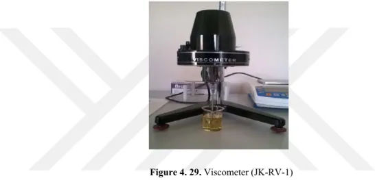
4.3. Viscosity of Electrospinning Solutions ... 43
4.4. Characterization Techniques ... 45
4.4.1. Scanning electron microscopy ... 45
4.4.2. X-rays diffraction ... 46
4.4.3. Contact angle setup ... 46
4.4.4. Four-point probe device ... 47
4.4.5. TGA and DSC setup ... 48
5. RESULTS AND DISCUSSION ... 50
5.1. Morphology and Diameters of Nanofibers ... 50
5.1.1. Morphology and diameters of pure PAN nanofibers ... 50
5.1.2. Morphology and diameters of composite nanofibers ... 51
5.2. Effect of Viscosity on Diameters of Electrospun Nanofibers ... 58
5.3. Electrical Conductivity of Nanofibers ... 60
5.3.1. Electrical conductivity of nanofibers containing copper nanoparticles ... 61
5.3.2. Electrical conductivity of nanofibers containing graphene nanoparticles .... 62
5.3.3. Electrical conductivity of nanofibers containing silica nanoparticles ... 63
5.3.4. Comparison of electrical conductivity of various composite nanofibers .... 64
5.3.5. Effect of fibers diameter on electrical conductivity ... 67
5.3.6. Effect of solution viscosity on electrical conductivity ... 68
5.3.7. Comparison of electrical conductivity values to the literature studies ... 70
5.3. Contanct Angle Results ... 72
5.3.1. Contact angle of graphene nanoparticles -based nanofibers ... 72
5.3.2. Contact angle of silica nanoparticles-based nanofibers ... 73
5.3.3. Contact angle of copper nanoparticles-based nanofibers ... 74
5.4. XRD- Results ... 75
5.4.1. XRD patterns of pure PAN and Cu/PAN nanofibers ... 75
5.4.2. XRD patterns of pure PAN and graphene /PAN nanofibers ... 76
5.4.3. XRD patterns of pure PAN and SiO2 /PAN nanofibers ... 77
5.5. Thermal Analysis. ... 78
5.6. Transmission Electron Microscopy ... 80
6. CONCLUSION AND RECOMMENDATIONS ... 82
6.1. Results ... 82
6.2. Recommendations ... 85
REFERENCES ... 86
xi
SYMBOLS AND ABBREVIATIONS
Symbols
cm : Centimeter
g/mol : Gram per mol
μm : Micrometer
H2O : Water
nC : Nanocoulomb
wt. : Weight
w/v : Weight per volume Fe3O4 : Iron oxide
MnO2 : Manganese dioxide N2H5OH : Hydrazinium Hydroxide SiO2 : Silica
Tp : Peak derivative temperature, inflection point, oC Tonset : Onset temperature, oC
μS/cm : Micro Siemens per centimeter
Abbreviations
AFM : Atomic Force Microscopy AgCl : Silver chloride
AgNPs : Silver nanoparticles
ATR-FTIR :Attenuated Total Reflection - Fourier-transform infrared spectroscopy CA : Contact angle
CNTS : Carbon nanotubes CS : Chitosan
CuNPs : Copper nanoparticles
DSC : Differential scanning calorimetry DMF : Dimethylformamide
DMSO : Dimethylsulfoxide
DMPC : Dynamic moisture vapor permeation cell DNA : Deoxyribonucleic acid
EMImBr : Ethyl-3-methylimidazolium bromide
FESEM : Field emission scanning electron microscopy Gr.NPs : Graphene nanoparticles
NMR : Nuclear magnetic resonance MWCNT : Multi-Walled Carbon Nanotubes PA6 : Polyamide 6
PAN : Polyacrylonitrile PEO : Poly (ethylene oxide) PLA : Polylactide
PMSQ : Polymethylsilsesquixane
PS : Polystyrene
PU : Polyurethane
PVA : Polyvinyl alcohol PVC : Polyvinyl chloride
xii PVP : Polyvinylpyrrolidone SAXC : Small angle X-ray scattering SEM : Scanning electron microscopy
SERS : Surface-enhanced Raman spectroscopy TEM : Transmission electron microscopy
UV : Ultraviolet
WAXD : Wide angle X-ray diffraction XPS : X-ray photoelectron spectroscopy XRD : X-rays diffraction
1. INTRODUCTION
Nowadays, nanomaterials have drawn great attention of many researchers due to their outstanding potential properties compared to their bulk counterparts and that they can be used in various areas. Different methods are used in order to produce nanofibers such as drawing, template synthesis, phase separation, self-assembly, Chemical vapor deposition, wet chemical synthesis, electrospinning and so forth (Huang et al., 2003).
Until now electrospinning has been considered to be relatively the simplest process for producing materials at nano-scale. However, it has been stipulated that the physic behind it is not easy to understand since the properties of the electrospun nanofibers can be significantly influenced by many parameters. Electrospun nanofibers present unique properties such as a high surface area to volume ratio, lightweight, high porosity, good thermal, mechanical, electrical and flexibility properties. Materials obtained from electrospinning technique can find a wide range of applications, notably in electronic, medicine, environment protection, energy conversion and storage, and so on.
Over the past few decades, electrospun nanofibers containing nanoparticles are generating considerable interest in terms of features enhancement. The incorporation of nanoparticles into polymers can provide novel or improved performance to the resultant composite fibers (Cavaliere, 2015). Despite this interest, no one to the best of our knowledge has studied the effect of copper NPs, silica NPs and graphene NPs on the electrical conductivity of their respective PAN composite fibers. With this in mind, we tried to investigate the diameter and electrical conductivity of PAN polymer nanofibers containing nanoparticles mentioned above. To do so, 1 wt. %, 3 wt. % and 5 wt. % of each type of nanoparticles were mixed in PAN/DMF solutions.
The aim of this thesis is to produce composite nanofibers (copper NPs, silica NPs and graphene NPs) using electrospinning technique and to examine their electrical conductivity performance using the four-point probe technique.
Nowadays, the mankind is in search of alternative energy sources to prevent various harmful effects caused by the use of fossil fuels. We have to find an emission-free energy source for our Earth. For this reason, new kind of materials are required which will perform the same function with less energy consumption and emission-free than conventional materials. We believe that nanocomposite materials planned to be
produced in this thesis can be find their applications in solar cells (PV) and proton exchange membrane fuel cells (PEMFC).
In the light of previous investigations on electrospinning process, there is considerable concern about electrospinning parameters since they can have a direct effect on the properties of the resultant fibers. In this study, among different parameters: solution concentration, solution viscosity and applied voltage were picked out so as to investigate their effect on the diameter and electrical conductivity properties of the as-spun composite nanofibers.
This current thesis is divided into six chapters. The first chapter is the Introduction which presents the problematic of the study. The second chapter exposes the literature survey of electrospinning process and the resultant fibers properties. The third chapter presents the concept of electrospinning technique, its parameters and the advanced characterization techniques of nanomaterials. The fourth chapter describes the materials and methodology employed in order to fabricate and analyze fibers containing nanoparticles. The fifth chapter reports research findings and results discussion. The sixth chapter presents the key findings of the research and recommendations for the forthcoming researches.
2. LITERATURE SURVEY
There have been many articles published on understanding the basic concepts of electrospinning process and the effects of diverse parameters on the morphology and geometrical properties of electrospun nanofibers and the incorporation of nanoparticles in polymer solutions. Some of them are presented in the following paragraphs.
Zhang et al. (2014) have successfully synthesized a new kind of memory nanocomposite device, consisting of a thermoplastic Nafion polymer and Electrospun polyacrylonitrile-based carbonized membranes of fibers. They found that by calibrating the applied voltage during the fabrication process of the PAN solutions, a significant enhancement of electrical conductivity of the carbon fibers was observed, notably from 7.85 to 12.30 S/cm.
Tapasztó et al. (2011) have investigated the dispersion patterns of graphene and carbon nanotubes in ceramic matrix composites. The experiment results have demonstrated a remarkably different distribution motif for graphene and nanotubes in the ceramix matrix. They observed that a good dispersion was obtained with few-layer graphene flakes. However, carbon nanotubes were chiefly found in the small aggregate structures form.
Levitt et al. (2017) have fabricated twisted assemblies of polyacrylonitrile (PAN), polyvinylidene fluoride trifluoroethylene (PVDF-TrFe), and polycaprolactone (PCL) nanofibers via a modified electrospinning setup, consisting of a rotating cone-shaped copper collector, two syringe pumps, and two high voltage power supplies. They reported that the fiber diameters and twist angles were found to vary as a function of the rotary speed of the collector. In addition, the mechanical testing of the yarns demonstrated that PVDF-TrFe and PCL yarns present a higher strain-to-failure than PAN yarns, reaching 307% for PCL nanoyarns. What is more, for the first time, the porosity of nanofiber yarns was studied as a function of twist angle, the results showed that PAN nanoyarns are more porous than PCL yarns.
Guclu et al. (2016) have studied the pore size and the strengthness of membrane manufactured via simultaneous electrospinning of PAN and polysulfone (PSU). The results of the study showed that polysulfone fibers had higher pore size than PAN fibers membranes. Nevertheless, for polysulfone fibers lower temperatures were sufficient so as to improve mechanical features against fiber rupture. It is of interest to
note that the pore size of PAN fiber membranes was araund 0.8 μm and 185°C was sufficient to improve the strength of polysulfone fibers against rupture.
Khan et al. (2017) have evaluated thermal behaviors of electrospun polyacronitrile (PAN) fibers incorporated with graphene nanoplatelets and multiwall carbon nanotubes (MWCNTs) using DSC and TGA. They have found that pristine PAN fiber presented a glass transition temperature (Tg) of 104.09°C. Their findings revealed that the glass transition temperatures of the composite fibers increased with an increase of nanoparticles contents (both for graphene and MWCNTs). But a further increase in nanoparticles contents led to the decrease of glass transition temperatures.
Tai et al. (2015) in their work have fabricated a lightweight and compressible sponge made of carbon-silica nanofibers via electrospinning process. Their experiment revealed that the fabricated sponge had high porosity (> 99%) and presented ultra-hydrophobicity and superoleophilicity, as results the fabricated materials have been found to be favorable to be usd as oil adsorbent.
Pant et al. (2011) have studied the effect of polymer molecular weight on the fiber morphology of electrospun mats. It was found that the prepared fibers were smooth and uniform in diameter along their lengths. In addition, their results revealed an increase in the wettability, mechanical strength and in the BET area as well as a decrease of the pore size in the electrospun mats. These phenomena were due to the presence of the double layer of two distinct fibers in the mats.
Cramariuc et al. (2013) examined the fiber diameter in electrospinning process. In their work, they hhave controlled two process parameters, namely applied voltage and polymer solution flow rate to reach the predetermined fiber diameters. At greater distances from the tip, the diameter of the fiber can be carried out as function of the density of the solution, the flow rate of the solution, the applied voltage and the distance from the tip. However, near the collector, the fiber diameter can be carried out as function of the surface tension of the electrospinning solution, the dielectric permittivity, the solution flow rate as well as the intensity of the electric current.
Rácová et al. (2014) have studied the influence of copper ions on mechanical properties of PVA-based nanofiber textiles fabricated by electrospinning process. According to the results of their experiment, they have that the addition of copper ions caused an increase of the strength and stiffness of the resultant nanofibers.
It has been reported that the selection of a desirable solvent or solvent system as the carrier of a particular polymer is fundamental for the optimization of
electrospinning. Luo et al. (2010) have developed a novel method of selecting solvents for polymer electrospinning. To do so, 28 solvents diversely positioned on the Teas graph were examined for the solubility and electrospinnability or making polymethylsilsesquixane (PMSQ) solutions. According to the results of their study, it was observed that suitable electrospinning solutions cannot be necessarily obtained by using solvents with high solubility. The results revealed that for a PMSQ solutions of the same concentration, the solution were found to present a good spinnability in a solvent with partial solubility than in solvent with high solubility.
There have been many attempts made by researchers to incorporate the metal nanoparticles whether in the solutions which will be electrospun or in the electrospun nanofibers in order to reach some required characteristics of materials in different fields of science.
Adding conductive additives to electrospinning solutions has been proven to increase the conductivity of electrospun membranes. Savest et al. (2016), they have investigated the effect of ionic liquids on the conductivity of electrospun polyacrylonitrile membranes. In their study three different ionic liquids namely BMlmCl, EMImBr and EMlmTFSI were used as additives in PAN solutions wherein the DMF and DMSO were used as solvents. They reported that with small increasing of the concentration of ionic liquids the membrane conductivity has significantly increased comparing to the membranes obtained from the pure PAN in DMF and PAN in DMSO solutions.
Heikkilä and Harlin (2009) examined the effect of the salt as conductive additive and CNTs as filler on the electrospinning process with polyacrylonitrile. They tried to vary some electrospinning parameters such as voltage, distance and nozzle size then they analyzed the quality of the electrospun web and fibers, as well as the functioning of the process. They reported that although the PAN and PAN/Salt solution presented nearly the same viscosity range but the PAN/Salt solution produced slightly larger fibers because the increased conductivity has an effect of enhancing the mass flow rate. In addition, they observed that the higher conductivity of the PAN/Salt solution increased the instabilities in the electrospinning process. Moreover, compared to the conductivity of PAN/CNT solution, the PAN/Salt solution presented a higher viscosity. Zhang et al. (2009) have made an investigation on fabrication and property analysis of electrospun polyacrylonitrile nanocomposite fibers reinforced with Fe3O4 nanoparticles. The experiments results demonstrated that slight changes in operating
parameters may lead in considerable changes in the fiber morphology. From SEM analysis they concluded that the beads can be avoid either by rising the solution concentration, distance and applied voltage to a certain level or by the reduction of the flow rate. The incorporation of Fe3O4 nanoparticles into the polymer matrix has a significant effect on the crystallinity of PAN and a strong interference between PAN and Fe3O4.
Crosslinked electrospun polyvinyl alcohol nanofibers coated by antibacterial copper nanoparticles were prepared and investigated by Rezaee and Moghbeli (2014). In their study, the poly (vinyl alcohol) nanofibers were prepared via electrospinning of concentrated PVA solutions. Then, in order to enhance their resistance against the moisture the nanofibers were crosslinked using glutaraldehyde as crosslinking agent in the presence of hydrochloride acid. In addition, the crosslinked nanofibers were coated by copper nanoparticles using electrospraying technique. The effect of the stabilizer concentration (0.001 and 0.005 M) and reduction temperature (25 and 75°C) were investigated on the copper nanoparticle dispersion in the media using UV-visible spectroscopy. They reported that UV spectra exhibited the most stable copper nanoparticle dispersion prepared using PVA stabilizer at higher reduction temperature (70°C) and the lower salt concentration (0.001M). This colloidal dispersion with 70 nm mean size was used to cover the crosslinked nanofibers via electrospraying process.
The effect of silver nitrate quantity on the morphology, conductivity and mechanical properties of PAN/AgNPs composite nanofibers were investigated by Demirsoy et al. (2015). They reported that bead-free and uniform composite fibers with diameters ranging from 499-515 nm were successfully electrospun. The results of the investigation revealed that the bursting stress and bursting elongation of the neat PAN nanofibers were lower than the PAN/Ag composite nanofibers. Moreover, the conductivity of the produced nanowebs was enhanced up to around 10-8 S/cm when the silver nanoparticles were dispersed in the solution.
An investigation on the preparation and characterization of gelatin nanofibers containing silver nanoparticles was done by Jeong and Park (2014). In their research, the gelatin nanofibers containing AgNPs were prepared by electrospinning process. After examination, the average diameters of the gelatin nanofibers was 166.52 ± 32.72 nm, which decreased with AgNO3.
Ji and Zhang (2008), worked on ultrafine polyacrylonitrile/silica composite fibers via electrospinning technique. Techniques such as SEM, TEM, ATR-FTIR, and
DSC were used to analyze the produced fibers. They reported that beads were formed and at silica contents higher than 2 wt. %, agglomeration of silica was observed in nanofibers. Furthermore, they observed that the addition of silica nanoparticles also changes the thermal properties of PAN/silica nanofibers.
The electrical conductivity and morphology of MWCNT-MnO2 within PVA nanofiber were investigated by Zamri et al. (2011). It was reported that the presence of MWCNT-MnO2 nanocomposites inside the PVA nanofiber was detected by TEM images. They discovered that the sizes of the pores of the nanofiber composite were smaller compared to those in the neat PVA nanofiber. Moreover, they highlighted that the PVA/MWCNT-MnO2 nanofiber composites showed an enhanced electrical conductivity of 6.99×10 Scm-1 compared to 5.26316×10 Scm-1 for PVA/ MWCNT without MnO2 and 1.25×10 Scm-1 for neat PVA.
Dung et al. (2016) have conducted research on the effect of copper salt concentration on electrospun CuO nanofibers for gas sensing application. They highlighted that the 12 g-device shows the best response to ethanol and LPG meanwhile the 6 g-device shows the best response to hydrogen. The devices show a good selectivity to hydrogen at both working temperatures of 350 and 400 °C. The best device shows a percentage response of 170 % to 1000 ppm hydrogen at 250 °C.
3. THEORETICAL BACKGROUND OF ELECTROSPINNING PROCESS
Contrary to conventional fiber spinning processes (wet spinning, dry spinning, melt spinning, and gel spinning) which can produice polymers fibers with diameters down to micrometer range, electrospinning technique is a process that is used to produce polymer fibers with diameter in the nanometer range (Frenot and Chronakis, 2003).
Electrospinning technique is considered as a variant of the electrostatic spraying (or electrospraying) process, as both methods use high-voltage to induce the formation of liquid jets. In electrospraying process, small droplets or particles are produiced as a consequence of the break-up of the electrified jet, whereas a solid fiber is collected as the electrified jet is stretched in electrospinning (Karakaş, 2015).
Electrospinning is recognized as a novel and efficient production process that can be employed to piece together fibrous polymer mats consisted of fiber diameters ranging from several microns down to fibers with diameter lower than 100 nm (Frenot and Chronakis, 2003). So far, the electrospinning process is considered to be the only process that can be further promoted for mass fabrication of one-by-one continuous nanofibers from different types of polymers (Huang et al., 2003).
3.1. Components and Basic Principles of Electrospinning Setup
A simple electrospinning setup consists of three major components: a high- voltage power supply, a collector, and a spinneret (Ding and Yu, 2014). A basic setup of electrospinning process is illustrated in Figure 3.1 below.
Although the setup for electrospinning seems to be simple, it has been reported that the physics behind it is extremely intricate and very new to researchers and requires the understanding of electro-statics, fluid rheology, and polymer solution properties (Ding and Yu, 2014).
The electrospinning technique is basically different from air or other mechanically governed spinning processes by the fact that the extrusion force is caused by the interference between an externally applied electric field and the charged polymer fluid. A higher applied voltage corresponds to a highly charged polymer solution. Therefore, two predominant forces (the electrostatic repulsion force and surface tension) come across the solution droplet at the tip.
Undergoing these electrostatic solicitations, a cone referred to the Taylor cone is observed when the intensity of the applied voltage increases up to a threshold where the hemispherical surface of the solution starts to elongate (Huang et al. (2003); Ding and Yu (2014)). An additional increase of the electric field leads the repulse electrostatic force to overpower the surface tension as results the charged jet of the solution is ejected from the tip of the Taylor cone (Huang et al. (2003); Frenot and Chronakis (2003); Karakaş (2015)).
The demeanor of the as-spun jet comprehends three main regions: the occurence of the Taylor cone, the kicking out of the straight jet and the unstable whipping region. The Figure 3.2 shows the behavior of the electrospun jet. A Taylor cone is a consequence of the interference of electrical charges on the polymer solution with external electric field. Since the Taylor cone undergoes a high applied voltage, an instability is created in the droplet and leading to the creation of single fluid jet. Beyond the straight path, the thrown fluid jet reachs the unstable region which is referred to whipping jet (Karakaş, 2015).
Figure 3. 2. Behavior of the electrospun jet (Huang et al., 2003)
3.2. Electrospinning Parameters
The electrospinning process is controlled by several parameters, which can affect the processing of polymer solutions into nanofibers. These parameters are basically regrouped into three categories: solutions parameters, governing variables, and ambient parameters. Solution parameters encompass viscosity, molecular weight, conductivity, molecular weight distribution, elasticity, and surface tension, and process parameters encompass electric field at the capillary tip, hydrostatic pressure in the capillary tube, feed rate and concentration, and the gap (distance between the tip and the collecting screen), and ambient parameters include temperature, humidity, and the air velocity in the electrospinning chamber (Huang et al. (2003); Frenot and Chronakis (2003); Ding and Yu (2014)). Since all these parameters significantly affect the morphology and structure of the electrospun nanofibers, it is possible to obtain nanofibers with the desired diameters and morphologies by controlling those parameters (Karakaş, 2015).
In recent years, the spinnability of different polymers in solution form or molten form was investigated by many researchers. Therefore, the electrospinning parameters and their various effects on the nanofiber morphology and structure are summarized below.
3.2.1. Solution parameters
The electrospinning process and its resultant fiber features are mainly affected by the properties of the polymer solution. For instance, the surface tension can influence
the occurrence of beads along the fiber length. The solution viscosity play a significant role in extending the elongation of the solution. This will in turn have an effect on the diameter of resultant electrospun fibers (Ramakrishna, 2005).
3.2.1.1. Polymer molecular weight, concentration and solution viscosity
The molecular weight is among the different parameters that affect the solution viscosity. It has generally reported that a polymer of high molecular weight disbanded in a solvent presents a higher viscosity than a solution of the same polymer having a low molecular weight (Ramakrishna, 2005). A polymer with a good enough molecular weight and a solution having a sufficient viscosity are generally required in order to produce fibers via electrospinning technique (Ramakrishna, 2005). As shown in Figure 3.3, for the same concentration, when a polymer with low molecular weight is used, the production of beads occurs instead of fibers. An increase in the molecular weight leads to smooth fibers, meanwhile fibers with a considerable diameter are obtained for a polymer with high molecular weight (Karakaş, 2015).
Figure 3.3. SEM photographs showing typical structure in the electrospun polymer for various molecular weights a) 9.000-10.999 g/mol, b) 13.000-23.000 g/mol, c) 31.000- 50.000 g/mol (solution concentration 25 wt. % (Koski et al., 2004)
The fiber diameter is recognized to be related to the electrospinning process. It has been reported that fibers diameter depends on the jet size and on the content of the polymer in the jets. It has been reported that during the traveling of a solution jet from the pipette onto the metal collector, the primary jet may or may not be split into multiple jets, resulting in different fiber diameters as can be observed in Figure 3.4. As long as no splitting is involved, the solution viscosity was found to be one of the most significant parameters influencing the fiber diameter. The higher the polymer
concentration the larger the resulting nanofiber diameters will be. In fact, Deitzel et al. (2001) mentioned that a rise in the polymer concentration leads to a rise in the fiber diameter according to a power law relationship.
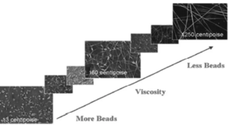
Figure 3.4. PLLA nanofibers with different diameters and pores (Huang et al., 2003) Defects such as pores and beads may occur in electrospun polymer nanofibers. It has been found that the polymer concentration also affects the formation of the beads (Jaeger et al., 1996). Fong et al. (1999) stated from their experiment that higher polymer concentration led to the formation of fibers with fewer beads. In addition, they have reported how the morphology of the fiber membranes has been altered by increasing the polymer concentration and therefore the solution viscosity. Figure 3.5 and Figure 3.6 show the effect of polymer concentration and the solution viscosity on the electrospun fibers.
Figure 3.6. SEM photographs of electrospun nanofibers from different polymer concentration solutions
(Fong et al., 1999)
It was reported that solution concentration and fiber diameter are linked in a power-law relationship. Hence, a rise in solution concentration leads to an increase in fiber diameter as can be observed in Figure 3.7 (Ding and Yu, 2014). Similar results have also been reported about other polymer fibers such as polyurethane (Cramariuc et al. (2013)), polylactide (Savest et al. (2016)), polyvinyl chloride (PVC), polyamide 6 (PA6), and chitosan (CS) (Ding and Yu, 2014), which indicated the significant role of polymer concentration and viscosity in controlling the structure of electrospun fibers.
Figure 3.7. FE-SEM images of electrospun PS fibers from various concentrations of (a) 5 wt. %, (b) 10 wt. %, (c) 20 wt. %, and (d) 30 wt. % (Ding and Yu, 2014)
3.2.1.2. Surface tension
Surface tension was recognized to be wert important in the electrospinning process. Therefore, attention must be paid when selecting a solvent to be used in the solution preparation, due to the fact that the surface tension is solvent composition dependent. A charged solution is needed so as the electrospinning process to take place (Ding and Yu, 2014). Generally speaking, a solution with a high surface tension impedes the process of electrospinning to occur. That is to say, a solution with a high surface tension leads to the instability of the jets as well as the creation of sprayed droplets.
The surface tension of the solution is wert important parameter due to the fact that the production of droplets, beads, and nanofibers is linked to it. It was reported that a solution having a lower surface tension allows the fabrication of fibers at a lower electric field. Such phenomena were encountered during the fabrication of PS, CS, PEO and PVC. In summary, keeping all variables unchanged, the surface tension delimits the range values in the electrospinning process (Ding and Yu, 2014).
3.2.1.3. Conductivity
A solution with a sufficient charge helps the repulsive forces within the solution to overthrow its surface tension and therefore to commence the electrospinning process. The facility of the solution to convey charges determines the outcomes of the electrospinning process that may be an eventual stretching or a drawing of the solution jet (Ding and Yu, 2014). Typically, fibers with smaller diameter are formed by increasing the electrical conductivity of the solution. Notwithstanding, uniform fibers with or without beads may be obtained by using solution with a low electrical conductivity (Ding and Yu, 2014). The existence of ionic salts in the solution, the types of polymer and solvent used in the solution preparation are the wert important parameters that affect the conductivity of the electrospinning solution (Karakaş, 2015).
3.2.2. Process parameters
External factors that influence the stability of the solution jet in electrospinning process are referred as process parameters. This category encompasses the applied
voltage, the temperature of the solution, the shape of the collector, the inner diameter of the needle, the feed rate and the gap between the needle tip and the collector. It was reported that the effects of these parameters on the morphology of the electrospun fibers are less significant than that of the solution parameters (Ramakrishna, 2005).
3.2.2.1. Applied voltage
Applied voltage is an important parameter in the electrospinning process. The use of high voltage allows the motion of the necessary charges, together with the external electric field will trigger the electrospinning process once the surface tension is overcome by the electrostactic force (Ding and Yu, 2014).
It has been reported that applied voltage and the resulting electric field both act on the jet acceleration and on the way of stretching the solution jet. Reseachers have reported that higher voltage leads to the formation of fibers with smaller diameters and helps the solvent to evaporate quickly, therefore, resulting in drier fibers (Buchko et al. (1999); Megelski et al. (2002)). Electrospinning of low viscosity solution at higher voltage may encourage the occurrence of secondary jets. In consequence, fostering the decrease of fiber diameters (Demir et al., 2002).
The flight time of the electrospinning jet may have also an influence on the diameter of the as-spun nanofibers. When the flight time is long, fibers take more time to stretch and elongate before it is deposited on the collector. Researchs have demonstrated that the flying time of the solution jet rises when a lower applied voltage and weaker electric field are used during the production of fibers. In this case, (Yang et al., 2004) reported that a voltage close to the critical voltage for electrospinning may be favorable to obtain finer fibers.
It is of interest to note that not only the high voltage may affect the physical appearance of the as-spun polymer nanofibers but also its crystallinity. The crystallinity of the fibers can be improved by using a high electrostatic field, wich results in more ordered molecules during the electrospinning process. However, above a certain voltage, the crystallinity of the fiber can be reduced. Furthermore, given sufficient flight time, the fabrication of fibers at higher voltage enhances the crystallinity of the electrospun fibers (Ramakrishna, 2005). In addition, it should be noted that the diameter of the fibers can be influenced by the applied voltage. However, the level of diameter
change depends also on parameters such as the concentration of the solution as well as the distance that separates the needle from the collector.
.
3.2.2.2. Feed rate
The feed rate is recognized to be among the key parameters in the electrospinning process due to the fact that a sufficient flow rate is required in order to maintain the stability of the Taylor cone (Ding and Yu, 2014). It was reported that the increase of the feed rate leads to an increase of fiber diameter or beads size (Ramakrishna, 2005). However, it was pointed out that there is a limit to the increase in the diameter of the fiber due to higher feed rate (Rutledge et al., 2000).
A higher flow rate is not recommended during the electrospinning process. This can be justified by the long time that takes the solution jet to dry (Ramakrishna, 2005). In order to give the solvent more time to evaporate a lower feed rate is more desirable (Yuan et al., 2004).
3.2.2.3. Tip to collector distance
As we have seen from the previous section, the flight time of the jet in electrospinning is a very important aspect to consider. Parameters such as flight time and the intensity of the electric field influence on the electrospinning process as well as on the resulting fibers. The flight time and the intensity of the electric field are directly affected by the change of the tip-collector distance. (Ding and Yu, 2014). Hence, an optimum gap between the needle tip and the collector is required. This statement may be justified by firstly allowing the fibers to have a sufficient time to dry and secondly to avoid the formation of beads when either the needle tip is too close or too far to the collector (Min et al., 2004).
On the other and, fibers with bigger diameters may be collected by using longer distance between the tip and collector. This phenomenon was explained as consenquence of the dimunition of the strength of the electrostatic field, which leads to poor stretching of the fibers (Bhardwaj and Kundu, 2010). Therefore, it clear to keep in mind that there is an optimum tip-collector distance which favors the evaporation of solvent for each electrospinning process (Ramakrishna, 2005).
3.2.2.4. Diameter of pipette orifice
It has been reported that even though electrospinning technique is simple but the technique behind it is not easy to understand due to the fact that the resultant fibers are influenced by many parameters. Like other work parameters, it was observed that fibers with a few number of beads were produced by using a needle with a smaller inner diameter (Mo et al., 2004). It was also reported that the decrease in the internal diameter of the needle was also found to reduce the diameter of the electrospun fibers. Nonetheless, a needle witth an extremely small inner diameter do not allow the solution droplet to be extruded from the tip of the needle(Ramakrishna, 2005).
3.2.2.5. Collector effect
In order to initiate the electrospinning process an electric field is required between the source and the collector. It was reported that collector should be fashioned with conductive materials so as to guarantee that the potential difference between the supplier apparatus and the collector can be maintained constant during the electrospinning process (Ramakrishna, 2005). It has been proved that a conductive collector helps to efficiently dissipate the charges on the fibers and therefore to allow a good distribution of the fibers on the collector (Liu and Hsieh, 2002).
Whether or not the collector is static or moving also have an effect on the electrospinning process. Where a rotating collector was used it was observed that the solvent took more time to evaporate and also helpt to increase the rate of evaporation of the solvents on the fibers. As results, the morphology of the fibers was enhanced where distinct fibers were required (Wannatong et al., 2004).
3.2.3. Ambient parameters
The influence of ambient parameters on the electrospinning process was not widely examined by several researchers. Any interaction between the surrounding and the polymer solution may result in changing the morphology of the electrospun fiber. It is well known that the fabrication of fibers via electrospinning process is also affected by the external electric field. Whence, any changes around the electrospinning device may disturb the electrospinning process (Ramakrishna, 2005).
3.2.3.1. Humidity
The humidity of the electrospinning vicinity may have an influence on the polymer solution during electrospinning. It was reported that at high humidity, it is likely that water condenses on the surface of the fiber when electrospinning is carried out under normal atmosphere (Ding and Yu, 2014). As a result, this may have an influence on the fiber morphology especially polymer dissolved in volatile solvents (Megelski et al., 2002). It is clearly showed from the open literature that increasing the humidity of the electrospinning vicinity enhances widely the porous structure. Further increasing the humidity, the depth, diameter, and number of the pores start to saturate. (Casper et al., 2004). Moreover, the humidity has an effective effect on the evaporation of the solvent since it determines the rate of evaporation of the solvent in the solution. When a volitile solvent is used at an extremely low humidity, the electrospinning process lasts only for a few minutes before the orifice tip is clogged. This phenomenon can be induced by a fast evaporation rate of the solvent compared to the time made to leave the tip of the orifice (Ding and Yu, 2014).
3.2.3.2. Type of atmosphere
The air composition in the electrospinning vicinity affects the fabrication of fibers. Researchs have revealed that gases behave in a different manner in the presence of high electrostatic field. For instance, from the open literature it was found that a gas such as helium breaks down. In such conditions, the electrospinning of the polymer solution becomes impossible. However, it was shown that when a gas with higher breakdown voltage is used such as Freon 12, the resultant fibers have twice the diameter of those electrospun in air keeping all other conditions unchanged (Baumgarten, 1971).
3.2.3.3. Pressure
It has been demonstrated that when the pressure is below atmospheric pressure, the polymer solution in the syringe will have a greater tendency to flow out of the needle and therefore causing unstable jet initiation. Generally, lowering pressure neighboring the solution jet does not ameliorate the electrospinning process. It has been
reported that with a very low pressure, the fabrication of fibers via electrospinning is not possible as a consequence of the direct discharge of the electrical charges (Ramakrishna, 2005).
3.2.3.4. Temperature
The viscosity of the solution decreases with the increase of the temperature while the increase of the temperature improves the rate of evaporation of the solvent (Demir et al., 2002). It is of interest to note that the use of a high temperature can result in a loss of functionality of the substance when biological substances such as enzymes and proteins are added to the solution for the electrospinning operation (Ramakrishna, 2005).
3.3. Characterization Techniques
Nowadays, there are many characterization techniques which help scientist and researchers to examine in depth the properties of nanomaterials. Some of them will be presented in the following sections.
3.3.1. Morphology characterization
In order to characterize the geometric properties of nanofibers such as fiber diameter, diameter distribution, fiber orientation and fiber morphology (e.g. cross-section shape, density and surface roughness) numerous techniques can be used, namely Scanning Electron Microscopy (SEM), Field Emission Scanning Electron microscopy (FESEM), Transmission Electron Microscopy (TEM) and Atomic Force Microscopy (AFM) (Huang et al., 2003). However, it is necessary to bear in mind that each microscopy has its own unique pros and cons. Among different geometrical characterization techniques mentioned above, SEM, and TEM will be set forth in following paragraphs.
3.3.1.1. Scanning electron microscopy (SEM)
A focused beam of high level energy is employed in SEM setup so as to beget images of a sample by generating several signals on its surface. SEM technique has an advantage of possessing tha ability of magnifying objects about 10 times up to 300 000 times with high resolution. Great information (such as crystalline structure, morphology, and chemical composition) concerning the sample are provided by the signals.
Scanning electron microscopy is an apparatus that is employed to investigate materials with size ranging from 1 micron to 1 nanometer. Contrary to the light microscopy which can generate images up to 200 nm as the best resolution, SEM can characterize materials with about 10 nm as high resolution (https://bioaccent.org).
3.3.1.2. Transmission electron microscopy (TEM)
Transmission electron microscopy is recognized as a powerful tool for characterizing several types of materials. Transmission electron microscopy has great advantages over other microscopy techniques, in that its ultrahigh imaging resolution can reach several angstroms on modern instrument, or even sub-angstrom level but also structural information since the electrons penetrate through the thin samples, and chemical compositional information due to the interaction of high-energy electrons with core electrons of the sample (Luo, 2015). In addition, the use of TEM does not require the sample in a dry state as that of SEM. Hence, electrospun nanofibers from a polymer solution can be directly observed under TEM (Ramakrishna, 2005). Compared to other microscopy techniques, however, the samples for transmission electron microscopy must to be thin enough, typically thinner than 100 nm, so as to be penetrate by electrons, while there is no such requirement for other microscopies (Luo, 2015).
3.3.2. Chemical characterization
Techiques such as Nuclear Magnetic Resonance (NMR) and Fourier Transform Infra-Red (FTIR) are commonly used to investigate the molecular structure of nanofibers (Huang et al., 2003).
Supermolecular structure describes the architecture of the macromolecules in a nanofibers, and can be analyzed by Optical birefringence , Wide Angle X-ray Diffraction (WAXD), Small Angle X-ray Scattering (SAXC) as well as Differential Scanning Calorimeter (DSC) (Ramakrishna, 2005) .
Generally, techniques such as XPS, FTIR-ATR analyses, and Water Contact Angle measurement are used to examine the chemical properties of nanofibers surfaces. What is more, the hydrophilicity of the nanofibers surface helps to investiagate the chemical properties of nanofibers (Huang et al., 2003).
Among different chemical characterization techniques mentioned above, contact angle will be presented in following section since it will be used in this thesis.
3.3.2.1. Water contact angle analysis
A wetting surface is analyzed by the contact angle (CA) technique. A contact angle is defined as the angle between the tangent to the liquid-fluid interface and the tangent to the solid surface at the contact line between the three phases (Mittal, 2006). Small contact angles (< 90°) correspond to hydrophilicity, while large contact angles (> 90°) correspond to hydrophobicity (Yuan and Lee, 2013). More specifically, a contact angle less than 90° means that surface is well wetted by the liquid (hydrophilic solid surface), and the fluid tends to have an important contact with the surface. However, contact angles higher than 90° generally indicate that the fluid tends to lessen its contact with the surface and form a compact liquid droplet. In other words the surface of the solid is hydrophobic.
A super-hydrophilic state is reached when complete wetting occurs, in other words when the contact angle is 0°, as the droplet turns into a flat puddle. Contact angles higher than 150° lead to surfaces referred as superhydrophobic surfaces. Under these conditions, the system presents almost no contact between the liquid drop and the surface. The so-called lotus effect is observed in this range of contact angles (Lafuma and Quéré, 2003).
.
Figure 3.9. Illustration of contact angles formed by sessile liquid drops on a smooth homogeneous
solid surface (Yuan and Lee, 2013)
3.3.3. Physical characterization
The ability of the electrospun nanofibers of favoring air and vapor transportation is commonly measured by a device called DMPC ( Dynamic Moisture Vapor Permeation Cell) (Huang et al., 2003).
Electrical transport properties of electrospun nanofibers can be characterized by various techniques such as two-point probe technique, four-point probe technique, and interdigitated electrodes.
Four-point probe technique will be presented in the following section since will be used in this thesis to investigate the electrical conductivity of the electrospun nanofibers.
3.3.3.1. Four-point probe technique
As can be seen in Figure 3.10 the four point probe setup consists of four equally spaced tungsten metal tips with finite radius. The four tips are designed in such way to be in contact with the sample under test.
Each tip is supported by springs on the end to underrate the sample damage during probing. The four metallic tips are part of an auto-mechanical apparatus, which moves up and down during the measurement process. A use of a high impedance current is required so as to supply a current through the outer two tips while the differential potential is measured between the two inner tips, ideally without drawing any current (http://www.sardarsinghsir.com).
4. MATERIALS AND METHODS
The main objective of this study is to investigate the electrical conductivity of electrospun nanofibers containing nanoparticles. The influences of applied voltage, the content of nanoparticles (Copper, Graphene and Silica) on morphology, diameter of nanofibers as well as electrical conductivity were characterized. In order to achieve this goal, specific objectives were settled as:
To find suitable processing parameters and beadless nanofibers; To test different nanoparticle contents;
To analyze the viscosity solutions changes for each type of nanoparticles; Characterization of the produced nanofibers by SEM, XRD, TEM,
Contact angle techniques, TGA and DSC;
The four-point probe technique was used to investigate the electrical conductivity of the obtained nanofibers.
4.1. Materials
In this work, polyacrylonitrile (PAN) and dimethylformamide (DMF) were picked out as polymer and solvent, respectively. Copper, graphene nanoplatelet and silica were selected as nanoparticles to be dispersed in the PAN/DMF solutions. The following sections present the products specification and /or the application fields.
4.1.1. Polyacrylonitrile
Polyacrylonitrile is a synthetic, semi-crystalline organic polymer resin, with the linear formula (C3H3N)n. Though it is thermoplastic, it does not melt under normal conditions. It degrades before melting. It melts above 300 °C if the heating rates are 50 degrees per minute or above. It is a versatile polymer used to produce large variety of products including ultra -filtration membranes, hollow fibers for reverse osmosis, fibers for textiles, oxidized PAN fibers (Gupta et al., 1998). PAN has properties involving low density, thermal stability, high strength and modulus of elasticity. These unique properties have made PAN an essential polymer in high tech.
Figure 4. 1. PAN specification (Sigma Aldrich Co.)
4.1.2. Dimethylformamide
N, N-Dimethylformamide (DMF) is among the most used solvent in the electrospinning process. DMF is used in many applications such as in the isolation of chlorophyll from plant tissues, reagent inorganic synthesis, a reducing agent, dehydrating agent, catalyst and so forth. (www.sigmaaldrich.com).
Figure 4. 2. DMF specification (Sigma Aldrich Co)
4.1.3. Copper nanoparticles
Copper nanoparticles are known for their high electrical conductivity. It is mainly used in electronics industry. It can be used in conducting coatings, inks and
pastes, raw material for electronic parts, catalysis for reactions such as methanol production, microelectronic devices, additive for lubricants, for wear resistant coatings, sintering additives etc. Technical properties of copper nanoparticles used in this work are as follows:
Cu purity (%): ≥ 99.8 (partially passivated by coating nanoparticles with 0.8 wt. % Oxygen for only safe shipping);
Bulk density (g/cm3): 0.2 - 0.4; True density (g/cm3) : 8.9; Color : dark brown; Shape : spherical; Crystal structure : cubic; Average particle size(nm): 25;
Specific surface area (m2/g) : 35 – 55;
Figure 4. 3. Copper nanoparticles specification (Nanografi)
4.1.4. Silica nanoparticles
The properties of nanoparticles are as follows: Purity (%) : 99.8;
Specific surface area :175-225 m2/g; Loss on ignition: typically 2-16 %; Appearance (form): powder; Appearance (color): White.
Figure 4. 4. Silica nanoparticles specification (Sigma- Aldrich Co)
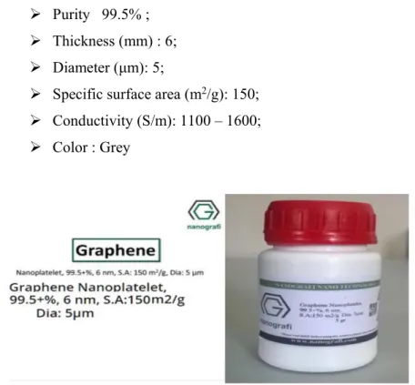
4.1.5. Graphene nanoparticles
The addition of Graphene to different composites show improvements in their physical properties. These improvements include electrical conductivity, thermal conductivity, hardness, strength, viscosity etc. Technical properties of graphene nanoparticles used in this study are as follows:
Purity 99.5% ; Thickness (mm) : 6; Diameter (μm): 5;
Specific surface area (m2/g): 150; Conductivity (S/m): 1100 – 1600; Color : Grey
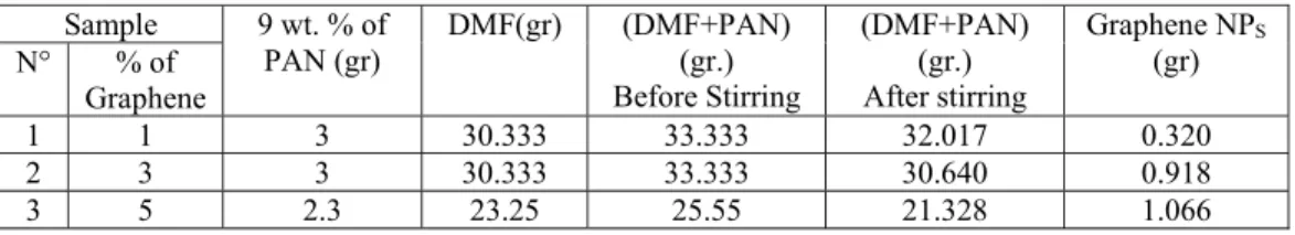
The equipment and chemicals used in this study for the preparation of the solutions, production and characterization of nanofibers are listed in the Table 4.1. In this project, all chemicals were used as- received without further purification.
Table 4. 1. List of materials
Equipments or chemicals Description
Polyacronitrile (PAN) 150,000g/mol of (Mw)
N, N- Dimethylformamide anhydrous, 99.8% From the Sigma Aldrich Co.
Copper From Nanografi, nanopowder 25nm %99.9
Graphene From Nanografi, Specific surface area 150m2/g
Silica From the Sigma Aldrich Co.
Collector Covered by the aluminum foil
Digital balance
High voltage power supply Magnetic stirrer
Magnetic fish Syringe pump
Stainless steel needles with 0.8ml as inner diameter.
SEM XRD TEM
Contact angle device Four-point probe device Gloves
masks Scissors
4.2. Parameters Setting and Preparation of Electrospinning Solutions
Setting of electrospinning parameters was recognized by many researchers as a crucial factor to the success of the process. Therefore, in this study some effective parameters ranges suggested by experts were used. Notably, 15 kV V 25 kV was selected to be the desired domain for applied voltage and 10 cm d 20 cm was considered as the effective range for spinning distance (Haghi, 2011). The electrospinning parameters used in this study are mentioned in the Table 4.2
Table 4.2. Electrospinning parameters for pure PAN electrospinning process Sample ( % wt. of PAN) Processing parameters Feed rate (mL/hr.) Tip to collector (cm) Collector Rotational speed(rpm) Applied voltage (kV) 8 2.5 12 112.5 10 15 20 9 2.5 12 112.5 15 20 10 2.5 12 112.5 15 20 11 2.5 12 112.5 15 20
According to our main objective, in this project two types of solutions were prepared. The first type refers to solutions prepared without nanoparticles and will be referred as pure PAN solutions in this document. The second type encompasses all solutions containing nanoparticles. In the following pages, the procedure used in order to prepare those solutions will be presented.
4.2.1. Fabrication of pure PAN nanofibers
A polyacronitrile (PAN) with an average molecular weight (Mw) of 150,000 g/mol and N, N-Dimethylformamide anhydrous, 99.8% were purchased from the Sigma Aldrich Co. all the materials were used as- received without further purification.
Different PAN/ DMF solutions with polymer content of 8 wt. %, 9 wt. %, 10 wt. % and 11 wt. % by mass were prepared. Two samples of PAN electrospinning solutions were prepared for each polymer Content highlighted above. For each electrospinning solution, the composition of its chemicals in terms of mass was summarized in the following Table.
Table 4. 3. Composition of electrospinning solution
Samples PAN (gr) DMF (gr) Solution (gr)
Number ( % wt. of PAN)
1 8 0.200 2.300 2.5
2 9 0.225 2.275 2.5
3 10 0.250 2.250 2.5
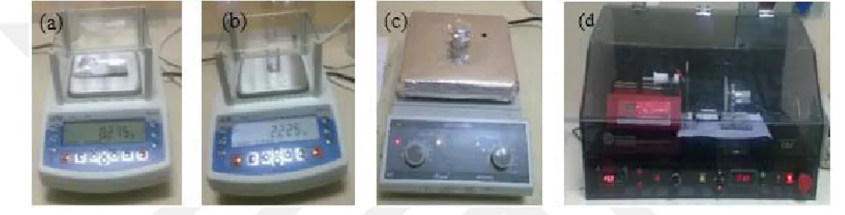
In order to prepare the electrospinning solutions, the amount of each polyacrylonitrile sample was dissolved in its DMF solvent quantity, respectively. Then, each solution sample was stirred using a magnetic stirrer device at 85°C and 1200 rpm for an hour so as to obtain a homogeneous electrospinning solution. A total of 9 solution samples were prepared under the same conditions. It is important to realize that after the homogenization process, in each case the solution sample was brought to the room temperature. After reaching the room temperature, the prepared electrospinning solutions were poured into a 2.5 mL syringe pump with 0.8 mm as inner diameter in order to proceed with the electrospinning setup. The following Figures (from Figure 4.6 to Figure 4.10) illustrate the procedure of the electrospinning solutions preparation.
Figure 4. 6. Main steps followed in electrospun nanofibers fabrication
Figure 4.7. Preparation and electrospinning process of 8 wt. % PAN polymer content solution. (a) 0.20 gr
of PAN, (b) 2.30 gr of DMF, (c) solution of PAN and DMF on the magnetic stirrer, (d) electrospinning process
Figure 4.8. Preparation and electrospinning process of 9 wt. % PAN polymer content solution. (a) 0.225
gr of PAN, (b) 2.275 gr of DMF, (c) solution of PAN and DMF on the magnetic stirrer, (d) electrospinning process
Figure 4.9. Preparation and electrospinning process of 10 wt. % PAN polymer content solution. (a) 0.250
gr of PAN, (b) 2.250 gr of DMF, (c) solution of PAN and DMF on the magnetic stirrer, (d) electrospinning process
Figure 4.10. Preparation and electrospinning process of 11 wt. % PAN polymer content solution. (a)
0.275 gr of PAN, (b) 2.225 gr of DMF, (c) solution of PAN and DMF on the magnetic stirrer, (d) electrospinning process
The experimental setup consisted of a syringe pump, sample collector and a high – voltage power supply, as shown in Figure 4.11 below. The spinning solution was held in a horizontal syringe with a stainless steel needle. The needle was electrically connected to a positive high voltage power supply. Whereas, the metallic disc used as collector was electrically connected to a negative high voltage power supply. The rotational speed of the collector during electrospinning was setup at 112.5 rpm (displayed as 15% of the maximum rotational speed of the collector on the electrospinning setup). The needle to the collector distance was 12 cm and the solution flow rate maintained at 2.5 mL/hr. using a digitally controlled syringe pump.
For each PAN polymer content at least two samples of nanofibers were produced at three different applied voltages (10 kV, 15 kV and 20 kV) keeping all the highlighted variables constant. The electrospinning process was carried out in a closed environment inside a transparent box at a room temperature as it can be seen from the Figure below.
Figure 4.11. Electrospinning setup
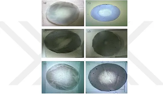
Under the setting parameters, the samples of the obtained nanofibers are shown in the following pictures.
Figure 4.12. Pictures of pure PAN electrospun nanofibers. (0) 8wt. % PAN and 10kV, (1) 8wt. % PAN
and 15kV, (2) 8wt. % PAN and 20kV, (3) 9wt. % PAN and 15kV, (4) 9wt. % PAN and 20kV, (5) 10wt. % PAN and 15kV, (6) 10wt. % PAN and 20kV, (7) 11wt. % PAN and 15kV, (8) 11wt. % PAN and 20kV. All the other variables remained constant
4.2.2. Morphology of electrospun pure PAN nanofibers
The nanofibers’ morphology has been reported as a main factor that affects the performance of electrospun nanofibers. Numerous electrospinning process parameters as well as polymer solution properties considerably affect the nanofibers’ morphology. In this project only the concentration and applied voltage parameters were considered while other electrospinning parameters were kept constant. Although such assumption
has been done, the possibility that some small variation in the charge density occurs as a result of charge dissipation from the tip into the atmosphere cannot be dismissed entirely.
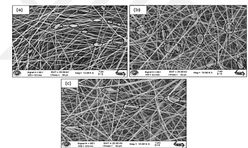
Morphological characterization was conducted with Zeiss Evo LS10 Scanning electron microscopy (SEM) of the advanced research center (Iltek) of the Selçuk University. Since a conductive coating is recommended to prevent charging of specimen with an electron beam in conventional Scanning Electron Microscopy technique, the obtained elecrospun nanofibers were brought in a sputter machine (Cressington Sputter Coater) in order to cover specimens with a thin layer of conducting material and therefore to increase the sample conductivity. Then, the coated nanofibers were characterized using SEM. The morphology and the diameter ranges of pure PAN nanofibers are presented from the Figure 4.13 to Figure 4.16 below.
Figure 4.13. SEM images of electrospun pure PAN nanofibers from various applied voltages and 8 wt. %
PAN Polymer content. (a) Morphology at 10 kV, (b) Morphology at 15 kV, (c) Morphology at 20 kV
Figure 4.14. SEM images of electrospun pure PAN nanofibers from various applied voltages and 9 wt. %