Kinect Based Intelligent Wheelchair Navigation with
Potential Fields
Mustafa ÖZÇELİKÖRS
1, Aylin ÇOŞKUN
2,
M. Girayhan SAY
3, Ahmet YAZICI
2 Eskişehir Osmangazi University1,2, Bilkent University3Eskisehir1,2, Ankara3, Turkey
[email protected], [email protected],
[email protected], [email protected]2
Uğur YAYAN
4, Mehmet AKÇAKOCA
4İnovasyon Mühendislik Ltd. Sti. ETGB4
Osmangazi Teknopark Eskisehir, Turkey
[email protected] [email protected] Abstract— Increasing elderly people population and
people with disabilities constitute a huge demand for wheelchairs. Wheelchairs have an important role on improving the lives and mobilization of people with disabilities. Moreover, autonomous wheelchairs constitute a suitable research platform for academic and industrial researchers. In this study, Finite state machine (FSM) based high-level controller and Kinect based navigation algorithm have been developed for ATEKS (Intelligent Wheelchair) which has high-tech control mechanisms, low-cost sensors and open source software (ROS, GAZEBO, ANDROID).
Keywords—Kinect; indoor navigation; intelligent wheelchair; mobile robots; ROS; Finite State Machine; potential fields.
I. INTRODUCTION
Independent mobility is very important for disabled and elderly people. Smart wheelchairs provide navigation assistance to these people in safe conditions [1]. Intelligent wheelchairs give them mobility and save them unnecessary physical efforts.Increasing number of these people creates a great demand to intelligent wheelchairs. According to this increment, there is a shift occurred from industrial robots to service robots.
A smart wheelchair is a platform that typically consists of either a standard power wheelchair to which a computer and a collection of sensors have been added or a mobile robot base to which a seat has been added [2]. This platform provides convenient research area on improving artificial intelligence for both academic and industrial researchers in literature; there are many different smart wheelchairs that use hardware and software applications for different usage.
Intelligent wheelchairs can be categorized into wheelchairs for commercial and research purposes. In literature, there are many commercial intelligent wheelchairs [3] [4] [5] [6] [7] which use different hardware and software components. In research [3], JiaLong intelligent wheelchair is introduced and hybrid map based navigation is presented. Hybrid map includes a series of small probabilistic grid maps (PGM) and global topological map (GTM). Localization, path planning and trajectory following algorithms are carried
out by using hybrid map. Lane curvature method (LCM) is chosen as velocity space controlling method in trajectory following. This wheelchair has controller for two wheeled differential driving, an industrial computer for management of information and a laptop for real time execution of navigation algorithm. The sensors are encoder-based odometer and laser range finder (LRF, SICK LMS100). As another intelligent wheelchair, iWheelchair [4] is developed with a DSP based embedded control system which uses 8 ultrasonic sensors for obstacle detection. In research [5], autonomous vehicle Tao Aicle is developed with laser range sensors, rotary encoder, GPS receiver and RFID reader. Navigation of this vehicle is performed by using data that are acquired from GPS and RFID landmarks. NavChair [6] has a DOS- based computer and 12 ultrasonic sensors as hardware equipments. In the high level control process, Vector Force Field (VFF) and Minimal Vector Field Histogram (MVFH) methods are used for performing obstacle avoidance. Another commercial wheelchair SENARIO [7] uses neural networks and sonar sensors for localization and has distributed control architecture.
Another category is the wheelchairs for academic use [8] [9] [10] [11] [12] [13] [14] that are developed for artificial intelligence applications and improve progress for high level control. In study [8], a low cost intelligent wheelchair MiiChair is developed. This vehicle has multi mode control system with a single chip controller that fuses ultrasonic, visual, and speech sensors. In addition, its sensors are encoder-based odometer and laser-range finder. These equipments show that the cost of this vehicle is very high and is not affordable. In research [9], Sharioto vehicle has shared control mechanism that performs obstacle avoidance with ultrasonic, infrared and LIDAR sensors. In study [10], SmartWheeler has laser range finders and odometers for navigation and obstacle detection. The mapping and navigation functions of the vehicle are provided by a special toolkit which can be used to build 2-D grid based mapping. The intelligent wheelchair Wheelesley [11] has 12 SUNX proximity (infrared), 6 ultrasonic sensors, and 2 Hall Effect sensors for sensing the environment. This vehicle has two control systems namely, high level control for directional commands and low level control for computer- controlled actions. The VAHM [12] project offers autonomous navigation based on internal map and semi-autonomous navigation with using infrared and ultrasonic sensors. In
research [13], OMNI-wheelchair provides hierarchy of functionality: simple obstacle avoidance, wall following etc. Mister Ed [14] has robot base with chair on top and has subsumption architecture on control mechanism.
In the previous study [15], a low-level control structure for the intelligent wheelchair ATEKS has been built. ATEKS is equipped with an embedded low-level controller, a high-level controller, ultrasonic sensors, Kinect sensor. It uses a map planning algorithm on an Android device, thus the planning process of ATEKS is external.
The aim of this study is to build a high level control structure and a behavior library. The high level control algorithm is intended to work as a FSM on the computer of ATEKS and the plan of the behavior comes from the user interface (KAB) as user input. The behavior data are processed along the sensor data in the high-level computer by using the developed behavior library. The behavior library presents a hybrid of the Potential Fields Method (PFM) and the Vector Field Histogram (VFH) for the Kinect data improvement in obstacle avoidance. The reason for developing this algorithm is that the Kinect is unable to perform the obstacle avoidance with plain Potential Fields Method, since it publishes too many data (640x480x8bytes). The developed algorithm reduces Kinect data to more useful form in order to use potential fields method for local navigation. This reduction is achieved by obtaining a 2D occupancy grid and dividing it into sectors using the sensor inputs. With this environment perception, many behaviors are performed such as movement in room (moving to a goal), doorway passing, corridor following, and parking. The study uses ATEKS for development, which has low-cost sensors and open source software (ROS, Gazebo) which shows that it is a platform for low-cost intelligent navigation applications.
This paper is organized as follows. In section 2, the 'ATEKS' intelligent wheelchair and FSM are introduced. Section 3 describes the Kinect based navigation algorithm. The tests are outlined in section 4.
II. SYSTEM OVERVIEW AND HIGH LEVEL CONTROL
SYSTEM
A. System Overview
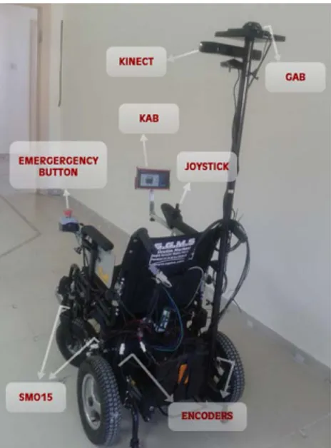
ATEKS (Fig. 1) [15] is an autonomous intelligent vehicle that performs sensor based and reactive-based indoor navigation behaviors.
Fig 1. ATEKS Platform
ATEKS Platform contains a low level controller (AKBL), a high level controller (AKBH), user interface module (KAB), 10 ultrasonic sensors (SMO15), encoders, joystick, motor driver, indoor positioning system (İÇKON) [16] and Kinect sensor (Fig. 2). Finite State Machine (FSM) based high level control uses potential fields based fusion algorithm (see Section 3) that combines the Kinect Sensor and other sensors (İÇKON and SMO15) for navigation. In Fig 2, the GAB is the unit which calculates position in İÇKON system.
Fig 2. ATEKS Platform and Peripherals
The Kinect (Fig. 3) has two distinct devices—an infrared camera and a standard RGB camera—that are processed into a single dataset by PrimeSense’s SoC. The layout of the device is shown in Fig. 3. The Kinect’s 3-dimensional imaging is accomplished by the infrared camera, which itself is comprised of two distinct parts that are managed by the SoC. The Kinect contains an infrared projector that emits a 640x480 grid of infrared beams. This grid leaves the Kinect in a conical projection and is reflected off of the environment. The Kinect then uses an infrared detector to
calculate the length of time it takes each beam to return to the device. The SoC then uses that measurement to extrapolate the distance from the device at each point, and returns a three-dimensional vector to the host machine that is comprised of data points between 40 and 2000. These data points correlate directly to the number of millimeters away the person or object is from the device [17].
Fig 3.Physical Layout of the Kinect
SMO15 sensor which has an accuracy of 1 cm and whose detection range is in between 2 and 5000 cm can measure and send distance over USB or CANBUS. SMO15 ultrasonic distance meter and Kinect sensor are integrated into the system for safe navigation [15].
B. Finite State Machine (FSM) Design
Finite state machines [18] are finite collections of states with transition rules that provide transition from one state to another. Basic components of the FSM are given in Fig. 4
Fig 4. Finite State Machine
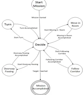
In this study, the circumstances of how a robot should act in indoor environments are considered. With the help of this idea, "Start Mission", "Decide", "Turn", "Move in Room", "Doorway Passing", "Follow Corridor", and "Mission Accomplished" (see Table I) etc. states are developed. Arcs between states are labeled “inputs” which represent external influences on the system. The names of inputs which can be seen in Fig. 5 are “Mission Started”, “Start Turn”, “Turn Accomplished”, “Start Move In Room”, “Move In Room Accomplished” and “Target Reached”. One of the states designates the “start state”, the state in which the system is placed initially. Moreover, it is often necessary to indicate one or more states as “final” or “accepting” states. In this study, the start state is named as
“Start Mission” and the final state is named as “Mission Accomplished”.
TABLE I. BEHAVIORS OF ATEKS FSM
Start Mission To actuate ATEKS, this state passes through to the Decide state with Mission Started input, thus the control mechanism is activated. Decide For each behavior, this state provides transition between states by checking
whether the destination is reached or not.
Turn Turn around and U turn is performed Movement in
Room In this state, ATEKS approaches to its destination and avoids objects. Doorway
Passing
ATEKS passes through the door. Follow
Corridor In this state, the corridor is followed. Mission
Accomplished This state terminates the task when all state transitions which are identified between two main target points are made successfully.
ATEKS FSM program is developed under Robot Operating System (ROS) [19] which is an open source middleware that provides the services expecting from an operating system, including hardware abstraction, low-level device control, implementation of commonly used functionality, message-passing between processes, and package management. It also provides tools and libraries for obtaining, building, writing, and running code across multiple platforms.
In Fig 5, ATEKS FSM flow diagram is shown. According to the mission plan, the FSM starts operation with the "Start Mission" and terminates operation with the "Mission Accomplished" state.
For the implementation of the states, Unified Model Language (UML) design was performed by using Visual Paradigm for UML (VP-UML) [20]. The VP-UML is the software which generates a skeleton code for the inputs and states given. Diagrams are used to view a system model. There are two ways: (1) - Static (or structural) view emphasizes the static structure of the system using objects, attributes, operations and relationships. (2)- Dynamic (or behavioral) view emphasizes the dynamic behavior of the system by showing collaborations among objects and changes to the internal states of objects.
State pattern is an UML model which is used for making flexible state transitions on the software side. State Pattern allows an object to alter its behavior when it’s internal state changes. That object will appear to change its class. The state pattern provides convenience when behavior of an object depends on its state, and it must change its behavior at run-time depending on that state. C++ code skeleton of state pattern is created by using VP-UML (see Fig. 6).
Fig. 6. State Pattern UML Diagram
III. KINECT BASED NAGIVATION ALGORITHM
The proposed ATEKS system is developed using low-cost sensors (Kinect, SMO15 etc.) and open-source software (ROS, GAZEBO, ANDROID). In this work, the ATEKS, which has sensor and reactive based hybrid structure and is running within a FSM, is simulated using GAZEBO 3D simulator. In this software, ATEKS model is constructed using dynamic and kinematic parameters of the robot itself. The simulator is used for simulating real indoor environment while developing behaviors.
In the implementation of Kinect-based navigation algorithm, the sonar sensors on ATEKS are used with Kinect. The sonar sensor information are obtained from the ATEKS GAZEBO model and right, right, left, front-left sonar are used to achieve more accurate and wider perception. These data are used in the force generation and scaling based on the behavior. Since a wider sensing area is needed for door passing, the right and left sensors of ATEKS are considered as more reliable in the mentioned behavior. The reliability of the sensors is indicated by a factor and is used in the force generation of the potential fields approach.
While developing the algorithm, the Kinect sensor data resolution is achieved by using award-winner Point Cloud
Library (PCL) [21]. This library resolves the raw sensor data into the data originated on Kinect coordinates.
In order to obtain the desired Kinect data, a coordinate transformation should be applied. This transformation transforms the data originated on Kinect coordinates into the data originated on robots center of gravity. In this work, the transformation is achieved using transformation matrix [22] and ROS' pcl_to_scan [23] application. Many features of ROS are used, such as publishing the coordinates in a node and visualizing the data obtained with the RViZ software, in this transformation.
The transformation of the data from Kinect originated to robot’s center of gravity coordinates is achieved by (1) and (2) [22], denoting wT
r as the transformation matrix and (x, y, θ) as robot’s center of gravity coordinates. The superscripts before the coordinates indicate whether the coordinates are robot or world coordinate.
cos sin sin cos 0 0 1 w r x T y θ θ θ θ − ⎛ ⎞ ⎜ ⎟ = ⎜ ⎟ ⎜ ⎟ ⎝ ⎠ (1) 1 1 w r w w r r x x y T y ⎛ ⎞ ⎛ ⎞ ⎜ ⎟ ⎜ ⎟ = ⎜ ⎟ ⎜ ⎟ ⎜ ⎟ ⎜ ⎟ ⎝ ⎠ ⎝ ⎠ (2)
The robot navigation is achieved by an algorithm that combines the potential fields algorithm [24] with the vector field histogram algorithm. In potential fields algorithm, navigation is carried out by constructing forces according to the sensor and target circumstances and transformation of the constructed forces into linear and angular velocities. The transformation of forces to velocities is a simple process of taking ratios considering the maximum linear velocity (Vmax)
and maximum angular velocity (ωmax) of the robot. The
repulsive forces are considered as objects whereas the attractive force is caused by the goal. In the potential fields method the repulsive forces (FR) and attractive forces (FA)
are calculated using (3), (4) and (5). dX and dY are the
distances from the detected object to the axes, whereas dmax
is the maximum perception distance and dGX and dGY are the
shortest distances from target to the axes (Fig 8). 2 2 max 1 X Y R d d F d ⎛ + ⎞ = ⎜ −⎜ ⎟⎟ ⎝ ⎠ (3) tan1 X R Y d d θ = − ⎛ ⎞ ⎜ ⎟ ⎝ ⎠ (4) sin cos 2 cos sin 2 X Y Y X G G A G G d d F d d ϕ ϕ ϕ ϕ ⎛ ⎞ − ⎜ ⎟ = ⎜ ⎟ ⎜ + ⎟ ⎜ ⎟ ⎝ ⎠ (5)
These equations return a force value between 0 and 1, and
ϕ
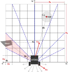
is taken as yaw angle of the robot. FA and FR are seenon Fig 7. The arrival to goal is detected by checking ε neighborhood around the goal. The doorway passing behavior is controlled by two control points placed 1 meter
from the door center and has the maximum perception distance of dmax-dp.
Fig 7. Grid and Sector illustration according to robot
In order to use the Kinect data for obstacle avoidance using potential fields, the 3D point cloud is reflected on the xy plane. The 2D Kinect data on the xy plane is represented using an occupancy grid. The sonar sensor data is also considered on the 2D occupancy grid while performing a behavior that needs wider and more accurate sensing, such as door passing. The occupancy grid is represented as a 2D grid matrix in the algorithm. The grid matrix approach is illustrated in Fig 7 and is used for unnecessary data reduction and environment perception. This grid matrix is programmed in modular characteristics and the indices (i, j) of the every point in the point cloud is calculated by using (6). The algorithm analyses every point in the point cloud and find their correspondent region indices (i, j) in order to check its content with a previously defined threshold value α to determine whether it is worth considering the grid as an obstacle or not. The symbols in (6) are shown in Fig 8, where Ux and UY demonstrate the 1-unit grid matrix width
and length.
( )
, X X , Y Y X Y R d R d i j U U ⎛⎢ − ⎥ ⎢ − ⎥⎞ = ⎜⎢ ⎥ ⎢ ⎥⎟ ⎣ ⎦ ⎣ ⎦ ⎝ ⎠ (6) As a second reduction, the grids are split into sectors which are shown by dashed lines in Fig 7, in order to overcome the local minima and inconsistent movement problems. With this approach, the obtained grid map is divided into polar sectors with the same sampling angle, θs,for every sector. The sectors are constructed by having a vector array, which contains the angle of the bisector with respect to -x axis and the grid-map range average of every sector. The forces to be used in potential fields algorithm are constructed using the bisector angle and average grid distance of each sector. The pseudo code in Table II is developed to demonstrate the transformation from grid matrix to sector matrix.
TABLE II. PSEUDOCODE FOR GRID TO SECTOR TRANSFORMATION for (i=0; i<grid_matrix.size(); i++)
for(j=0; j<grid_matrix[i].size(); j++) if(grid_matrix[i][j] >= threshold) sector_num = FindSectorNum(TGx,Ti,Ts,TSC); sector_matrix[sector_num][0] += 1.0; sector_matrix[sector_num][n] = R; n = n+1;
In this pseudo code; TGx demonstrates the angle between grid and x-axis, Ti demonstrates the start angle of sector, Ts demonstrates the angle of the sectors (θs in Fig 7),
and TSC demonstrates the total sector count. R demonstrates the average distance of grid distances contained by the sector. In the constructed sector matrix, the 0th index content shows the sector count, whereas the rest indices indicate the distances of contained grids to the center of gravity of the robot. These distances are used to find average grid distance of the sector (parameter "R") in order to generate forces that are used in potential fields method. The FindSectorNum function in the pseudo code above is achieved by using (7). This equation is used to find the correspondent sector index for any grid.
1 0 1 0 2 i x x s x x s T TG if TG T S TG TSC if TG T ⎧⎢ − ⎥ + < ⎪⎢ ⎥ ⎪⎣ ⎦ = ⎨ ⎢ ⎥ ⎪ − + > ⎢ ⎥ ⎪ ⎣ ⎦ ⎩ (7)
These vector parameters are subjected to potential fields algorithm in order to achieve obstacle avoidance. The system also has a collision avoidance function, which is triggered by the violation of maximum allowed distance of sensors. The distance parameters differ in behaviors, since the "doorway passing", "move in room", and "follow corridor" behaviors require different spaces to move. It is also important to note that the behaviors are achieved by using a "Mission Plan" file which contains the min-max distances, control point coordinates, and the perception parameters (such as maximum grid size, sector sampling angle etc).
The algorithm is developed using ROS middleware and tested on GAZEBO simulator [25]. The test results are given in section 4.
IV. SCENARIO TESTS
The scenario tests regarding systems performance are done using GAZEBO simulator. GAZEBO simulator allows modeling robots and environments with real kinematic and dynamic parameters such as moment of inertia and friction forces. The indoor environment (ESOGÜ Osmangazi Teknopark first floor) that is created using GAZEBO is given in Fig 8.
Fig. 8 Gazebo Indoor Test Environment
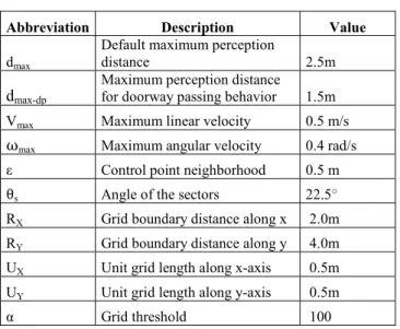
The two scenarios regarding robot's behaviors are designed to be based on the needs of a person who uses wheelchair. In Fig 8, the robot performs the Scenario1 between nodes 1 and 6, whereas it performs the Scenario2 between nodes 7 and 13. The behavior constant values which are mentioned in Section 3 and chosen for tests are seen on Table 3. In the table, maximum perception distance, control point neighborhood, and the parameters of grid considering Fig 7 are given. It should be noted that the grid is constructed by using 4 meters of maximum perception distance, but it is reduced to a distance of dmax = 2.5m or
dmax-dp = 1.5m depending on the behavior performed, while
transforming the grids to sectors.
TABLE III. BEHAVIOR CONSTANT VALUES FOR TESTS
Abbreviation Description Value
dmax
Default maximum perception
distance 2.5m
dmax-dp
Maximum perception distance for doorway passing behavior 1.5m
Vmax Maximum linear velocity 0.5 m/s
ωmax Maximum angular velocity 0.4 rad/s
ε Control point neighborhood 0.5 m
θs Angle of the sectors 22.5°
RX Grid boundary distance along x 2.0m
RY Grid boundary distance along y 4.0m
UX Unit grid length along x-axis 0.5m
UY Unit grid length along y-axis 0.5m
α Grid threshold 100
The position graph of Scenario1 is shown in Fig 9. In Fig 9, obstacles of the environment, the path of the robot, starting and finishing positions, nodes (asterisks in Fig 9), and ε neighborhood of the nodes are shown. It is seen that the robot changes its state as it enters the ε neighborhood, which is the indication that the goal of the state is reached. It is also shown that between nodes 1 and 2, robot doesn't do any oscillations because of using an occupancy grid approach and having relatively small distance of maximum
perception. The robot would do oscillations if the maximum distance perceived by Kinect was bigger, since the robot would be affected by more and unnecessary obstacles. In addition, the robot would tend to go slower if the maximum perception distance was longer, since the magnitudes of the forces created would become bigger.
Fig 9. Scenario1 Position Output
Fig 9 also shows that the robot performs the movement between nodes 5 and 6 successfully, despite the fact that the intensity of the objects is increased. This shows that the grid to sector reduction that is performed to Kinect works successfully for indoor environments regardless of the intensity of objects.
The linear and angular velocity-time behavior outputs (reference inputs) are seen in Fig 10. In the figure, it is demonstrated that before the doorway passing behavior, the robot adjusts its heading towards the next goal, thus has constant angular velocity, in order to improve the doorway passing performance.
Fig 10. Scenario1 Linear and Angular Velocity - Behavior Outputs
The behavior outputs that are seen in Fig 10 is applied to the robot in order to achieve the behavior. The velocity outputs of the robot according to the behavior outputs are shown in Fig 11. It is seen that the robot can apply the behavior outputs with small error.
Fig 11. Scenario1 Measured Velocities
In Scenario2, the robot moves through a different path and at the end it parks. In parking behavior, which is a meta-state of Move In Room meta-state, the robot moves through an arc shape and checks the w orientation of the robot within a small error rate in order to be parallel to the object. The position output of Scenario2 is seen in Fig 12. The figure shows the movement path of the robot in its environment. It is seen that in the corridor passing state, the robot remains steady and doesn't do any oscillations.
Fig 12. Scenario2 Position Output
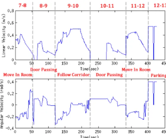
The linear and angular velocity outputs are shown in Fig 13. In the figure, it is seen that at a certain point between nodes 11 and 12, the collision avoidance is activated because of a leg of the table (seen in Fig 8). Because of the inertia, the robot cannot completely stop and manages to avoid the object.
Fig 13. Scenario2 Linear and Angular Velocity - Behavior Outputs
The velocity outputs of the robot according to the behavior outputs are shown in Fig 14. In Scenerio2, the robot is also able to perform the movement with small error. The velocity outputs of both Scenerio1 and Scenerio2 show that there is no velocity loss at the state transitions, which indicates that the FSM does not interrupt the behavior algorithm at the state transitions.
Fig 14. Scenario2 Measured Velocities
The test videos regarding robot's movement is accessible on link [26].
V. CONCLUSION &FUTURE WORK
As a result, in this work a finite state machine based high-level controller and Kinect-based navigation algorithm were developed for the ATEKS. It is seen from the graphs that Kinect is a sensor that could be used in autonomous robot solutions. The system is able to perform the behaviors that are necessary for indoor navigation. As a future work, the system will be tested on the real ATEKS robot.
ACKNOWLEDGEMENTS
This work is supported by Inovasyon Muhendislik under the TUBITAK project.
REFERENCES
[1] Moslehi, Hamid Reza , “Design and Development of Fuzzy Logic Operated Microcontroller Based Smart Motorized Wheelchair,” Ph.D Thesis, Dalhausie University, Halifax Nova Scotia (April 2011). [2] Richard C. Simpson, “Smart wheelchairs: A literature review ,
Journal of Rehabilitation Research & Development. ” Volume 42, Number 4, Pages 423–436 July/August 2005.
[3] Y. Wang, W.Chen, “Hybrid Map-based Navigation for Intelligent Wheelchair”, Robotics and Automation (ICRA), 2011 IEEE International Conference, pp. 637 - 642, May 2011.K. Elissa, “Title of paper if known,” unpublished.
[4] Lu T., Yuan K., “An embedded Control System for Intelligent Wheelchair”, IEEE-EMBS 2005, Engineering in Medicine and Biology Society, pp.5036-5039, Jan. 2006.
[5] O. Matsumoto and K. Komoriya, “Autonomous Traveling Control of the ‘TAO Aicle’ Intelligent Wheelchair”, Proc. of the 2006 IEEE/RSJ Int. Conf. on Intelligent Robots and Systems, pp. 4322–4327, Beijing, China, Oct. 2006.
[6] S.P. Levine, D.A. Bell, L.A. Jaros, R.C. Simpson, Y. Koren, J. Borenstein, “The NavChair assistive wheelchair navigation system, ” IEEE Transactions on Rehabilitation Engineering 7 (4) (1999) 443_451.
[7] N.I. Katevas, N.M. Sgouros, S.G. Tzafestas, G. Papakonstantinou, P. Beattie, J.M. Bishop, P. Tsanakas, D. Koutsouris, “The autonomous mobile robot SENARIO: a sensor-aided intelligent navigation system for powered wheelchairs, ” IEEE Robotics & Automation Magazine 4 (4) (1997)60_70.
[8] J. Liu, H. Zhabg, B. Fan, G. Wang, J. Wu, “A novel economical Embedded Multi-Mode Intelligent Control System for Intelligent Wheelchair”, 2010 International Conference on Computing, Control and Industrial Engineering (CCIE), vol.1, 156-159, June 2010. [9] D. Vanhooydonck, E. Demeester, A. Hüntemann, J. Philips, G.
Vanacker, H.V.Brussel, M. Nuttin, “Adaptable Navigation Assistance for Intelligen Wheelchairs by Means of an Implicit Personalized User model”, Robotics and Autonomous Systems 58 (2010) 963_977. [10] J. Pineau, A. Atrash, “SmartWheeler: A Robotic Wheelchair Test-bed
ofr Investigating New Models of Human-robot Interaction, ” Multidisciplinary Collaboration for Socially Assistive Robotics, Papers from the 2007 AAAI Spring Symposium, Technical Report SS-07-07, Stanford, California, USA, March 26-28, 2007.
[11] H. Yanco, “Shared user-computer control of a robotic wheelchair system, ” Ph.D. Thesis, Massachusetts Institute of Technology (September 2000).
[12] Bourhis G, Moumen K, Pino P, Rohmer S, Pruski A. “Assisted navigation for a powered wheelchair. ” Systems Engineering in the Service of Humans: Proceedings of the IEEE International Conference on Systems, Man and Cybernetics; 1993 Oct 17–20; Le Touquet, France. Piscataway (NJ): IEEE; 1993. p. 553–58.
[13] Borgolte U, Hoyer H, Buehler C, Heck H, Hoelper R. “Architectural concepts of a semi-autonomous wheelchair. ” J Intell Robotic Syst. 1998; 22(3/4): 233–53.
[14] Connell J, Viola P. “Cooperative control of a semi-autonomous mobile robot.” Robotics and Automation: Proceedings of the IEEE International Conference on Robotics and Automation (ICRA); 1990 May 13–18; Cincinnati, OH. Piscataway (NJ): IEEE; 1990. p. 1118– 21.
[15] B. Akar, U. Yayan, H. Yücel, V. Bayar, A. Yazıcı, "Akıllı Tekerlekli Sandalye Kontrolü İçin Sonlu Durum Makinesi Tasarımı", Otomatik Kontrol Ulusal Toplantısı, pp 20-21, 2012
[16] C. Yeniceri, T. Tuna, A. Yazici, H. Yucel, U. Yayan, V. Bayar, “A Smart Solution for Transmitter Localization”, Innovations in Intelligent Systems and Applications (INISTA), pp 1-5, 2013
[17] T. Bryce Blair, C. Eric Davis, "Innovate Engineering Outreach: A Special Application of the Xbox 360 Kinect Sensor"
[18] ULLMAN - Introduction to Automata Theory and Computations, Pg. 4
[19] http://wiki.ros.org
[20] http://www.visualparadigm.com/product/vpuml/
[21] R. B. Rusu and S. Cousins, "3D is here: PointCloud Library (PCL)", ICRA Communications, 2011
[22] Daniel E. Koditschek, "Robot Kinematics and Coordinate Transformations", 24th Conference on Decision and Control, Ft. Lauderdale, FL, December, 1985
[23] http://wiki.ros.org/pcl_to_scan
[24] Oussama Khatib, "Real-Time Obstacle Avoidance Manipulators and Mobile Robots", The International Journal of Robotics Research, Vol 5 No 1, Spring 1986
[25] http://gazebosim.org