Proceedings of ASME 2013 4th Micro/Nanoscale Heat & Mass Transfer International Conference MNHMT 2013 December 11-14, 2013, Hong Kong, China
MNHMT2013-22181
SIMULATION OF AN INTEGRATED MICROFLUIDIC DEVICE FOR BIOPARTICLE
WASH, SEPARATION AND CONCENTRATION
Barbaros C¸ etin∗
Microfluidics & Lab-on-a-chip Research Group Mechanical Engineering Department
˙Ihsan Do˜gramacı Bilkent University Ankara 06800 TURKEY Email: [email protected]
S ¨uleyman B ¨uy ¨ukkoc¸ak
Department of Mechanical Engineering TOBB University of Economics and Technology
Ankara 06560 TURKEY Email: [email protected]
Soheila Zeinali
Microfluidics & Lab-on-a-chip Research Group Mechanical Engineering Department
˙Ihsan Do˜gramacı Bilkent University Ankara 06800 TURKEY Email: [email protected]
B ¨ulent ¨Ozer
Department of Mechanical Engineering TOBB University of Economics and Technology
Ankara 06560 TURKEY Email: [email protected]
ABSTRACT
Washing, separation and concentration of bioparticles are key operations for many biological and chemical analyses. In this study, the simulation of an integrated microfluidic device is studied. The proposed device has the capability to wash the bioparticles (transferring the bioparticles from one buffer solu-tion to another), to separate the particles based on their dielec-tric properties and to concentrate the bioparticles. Washing and concentration of bioparticles are performed by acoustophoresis and the separation is performed by dielectrophoresis. For sim-ulating the flow within the microchannel, a computational fluid dynamics model using COMSOL Multiphysics software is imple-mented. In order to simulate the particle trajectories under ul-trasonic and electric field, point-particle assumption is chosen using MATLAB software. To account for the size variation of the bioparticles, particles with normal size distributions are used
in-side the microchannel. The effect of the key design parameters such as flow rate, applied voltage etc. on the performance of the device is discussed.
NOMENCLATURE
c dimensionless concentration D diffusion coefficient E electric field Fdrag drag force
FDEP dielectrophoretic force
FACT acoustic force
fCM Clasius-Mossotti factor
k wave number (= ω/c) u fluid velocity vector up particle velocity vector
P pressure R particle radius
Re[·] Real part of an complex quantity t time
xp position of the particle xo initial position of the particle ε permittivity ˜ε complex permittivity σ electrical conductivity ω frequency φ electrical potential ˆφ potential phasor µ viscosity of the liquid µDEP dielectrophoretic mobility
µACT acoustophoretic mobility
ρ density of the liquid (·)m medium
(·)p particle
(·)rms root-mean-square of an quantity
< · >p time averaged quantity
INTRODUCTION
Washing, separation and concentration of bioparticles are key operations for many biological and chemical analyses. Washing refers to the transfer of the bioparticles from one buffer solution to another, separation refers to the collecting bioparticles at different outlet according to their size or intrinsic properties, concentration refers to the increase in the of particles per unit volume in a buffer solution. Many label-free techniques have been proposed such as acoutophoretic [1], dielectrophoretic [2], hydrodynamic [3] to accomplish these tasks. Each method has its own advantages and drawbacks. In this study, a device with a hybrid approach is proposed. Ultrasonic and dielectrophoretic fields are utilized to perform bioparticle wash, separation and concentration functions of the microdevice. Each of these two methods has their strengths and weaknesses. It is aimed to use the strength of each method in different functions performed by the microdevice. The ultrasonic field is generated throughout the entire length of the channel which enables the ultrasonic field to manipulate the movement of the microbeads at every location in the channel [4, 5]. The dielectrophoretic method moves the microbeads with an electric field generated around the electrodes, since its strength is significant around the elec-trodes. Hence, it is not the best choice for manipulating particles throughout the entire channel. On the other hand, it has been shown in several studies that dielectrophoretic method can be effectively used to separate different types of bioparticles from each other. The acoustophoretic method can also be used to sep-arate cells/microbeads from each other but acoustic properties of different types of cells are not well known; therefore, its effec-tiveness in separation of cells are not well understood for sev-eral cell types. These strengths and weaknesses of each method lead us to design a microdevice where washing and concentration
of beads are performed by an ultrasonic field since these func-tions require manipulation of microbead posifunc-tions throughout the entire microchannel. The separation is performed using dielec-trophoresis method since its effectiveness on bioparticle separa-tion has been established over a decade [2].
The DEP force acting on a spherical particle is given by [2],
hFDEP(t)i = 2πεmR3
R
e[ fCM]∇E2rms, (1)where Ermsis the root-mean-square magnitude of the applied AC
electric field and fCMis the CM factor and is defined as,
fCM(˜εp, ˜εm) =
˜εp− ˜εm
˜εp+ 2˜εm
. (2)
When
R
e[ fCM] < 0, the phenomena is callednegative-dielectrophoresis (n-DEP) and particles are repelled by the elec-trical field strength maxima. When
R
e[ fCM] > 0, thephenom-ena is called positive-dielectrophoresis (p-DEP) and particles are attracted by the electrical field strength maxima. Theoretically, −0.5 <
R
e[ fCM] < 1.0 [2].The acoustic force acting on a spherical particle in a rectan-gular channel is given by [1]
hFACTi = 4πkR3< E
ac> φ sin(2ky) ˆj (3)
where < Eac> is the average energy density of the incoming
acoustic-wave, and φ is the contrast factor and defined as,
φ = 5ρp− 2ρ 3(2ρp+ ρ) −(c/cp) 2 3ρp/ρ , (4)
where ρp is the particle density, ρ is the fluid density, c is the
speed of sound in fluid, cpis the speed of sound in the particle.
The sign of the contrast factor determines whether a particle is moved towards pressure nodes or pressure antinodes.
In this study, the numerical simulation of an integrated mi-crofluidic device for bioparticle wash, separation and concentra-tion is presented. The microfluidic device consists of washing, separation and concentration sections. Washing and concentra-tion of bioparticles are performed by acoustophoresis and the separation is performed by dielectrophoresis. For simulating the flow within the microchannel, a computational fluid dynamics model using COMSOL Multiphysics software is implemented. To account for the size variation of the bioparticles, particles with normal size distributions are used inside the microchannel. The effect of the key design parameters such as flow rate, applied voltage etc. on the performance of the device is discussed.
Figure 1. Schematic drawing of the device
THEORETICAL ANALYSIS
The schematic drawing of the system is given in Fig. 1. The device consists of three sections: (i) washing section, (ii) sepa-ration section and (iii) concentsepa-ration section. The height of the channel is 100 µm. The width of the channel is 375 µm for wash-ing and concentration sections and 100 µm for the separation sec-tion. The lengths of the washing and concentration section are 12 mm, and the width of the piezoelectric material is chosen as 10 mm for the ease of installation. Reservoirs A and B are the inlets, and D and C are the exit reservoirs. There are also 4 other reservoirs for the waste. The particles suspended in buffer solu-tion A are loaded into the reservoir A, and the buffer solusolu-tion B is loaded into the reservoir B. As the solutions flow through the washing section, the particles suspended in the buffer solution A move to the middle of the microchannel where the buffer solution B is present. The particle movement towards the middle of the microchannel is achieved by the ultrasonic field which is gener-ated through the excitation of the channel walls with piezoelec-tric plate. At the end of the washing section, the buffer solution A flows out through waste reservoirs. The particles concentrated in the middle flow through the separation section. Within the sep-aration section, there exist electrodes to utilize dielectrophoretic separation (one large electrode and couple of small electrodes are introduced in this section to increase the efficiency of the sepa-ration). At the exit of the separation section, the n-DEP parti-cles flow through the upper branch and the p-DEP partiparti-cles flow through the lower branch of the T-junction. In the concentration section, the particles are again directed towards the center of the microchannel to be guided to flow into the reservoir C and D by the acoustic forces.
The motion of the particles would be the result of the hydro-dynamic, electrical and acoustic forces. Therefore, the flow and
electric fields should be determined to calculate the drag and the dielectrophoretic force. The acoustic force for a spherical parti-cle in a standing wave is given by Eq, (3). The frequency of the acoustic field is determined as a function of the channel width.
The flow field is governed by Navier-Stokes equation, ρ~u· ∇~u = −∇P + µ∇2~u. (5)
The electric field is governed by the Laplace Equation, ∇2ˆφ = 0. (6) Since an AC field is applied, ˆφ is the phasor of the applied elec-trical potential. The actual potential is φ(x,t) = ˆφ(x) f (t), where
f(t) is the functional form of the transient electrical field. To demonstrate the cell washing, the concentration field is simulated. The concentration field is governed by convection-diffusion equation,
u · ∇c = D∇2c, (7)
where c represents the dimensionless mole fraction of the buffer solution B.
In the simulation of the particle trajectories, point-particle approach is used and the effect of the particle on the field vari-ables is ignored, only the effect of the field varivari-ables on the parti-cle is considered. The field variables are determined without the presence of the particles. Together with the following assump-tions;
(1) the thermo-physical properties of the liquid are constant and there is no thermal effect on flow field and particle velocity, (2) the particle and the channel walls are non-porous, and do not
react with the surrounding liquid,
(3) the rotation of the particle does not affect the particle’s trans-lation motion,
(4) creeping flow,
(5) the electrostatic interaction between the particles is ne-glected,
the particle position xpcan be determined, by integrating the
par-ticle velocity together with the initial position,
xp(t) = xo+
Z t
0
up(τ)dτ, (8)
where xois the initial position of the particle, and t is the time.
For a fixed frame of reference, the translational motion of a particle is governed by,
mp
dup
Figure 2. 2D computational domain
where mpis the particle mass and Fext is the net external force.
In our case, the external force is composed of drag, dielec-trophoretic and acoustic forces.
The drag force on a spherical particle is given by,
Fdrag= 6πµR(u − up), (10)
at the creeping-flow limit, which is known as Stoke’s law [6], where R is the particle radius, u is the fluid velocity, up is the
particle velocity. The DEP and acoustic forces acting on a spher-ical particle are given by Eqs. (1) and (3) respectively.
For the particle size considered in this study, the characteris-tic time scale of acceleration period of the motion is in the order of 10−4s [7] which is much smaller than the time scale of the variation of the field variables. Therefore, the acceleration term can be safely neglected. It can be assumed that the particles move with the terminal speed at all times. Substituting Eqs. (1), (3) and (10) into the Eq. (9), the particle velocity can be obtained as, up= u − µDEP∇E2rms− µACPsin(2ky) ˆj. (11)
where muDEP and µACP are the dielectrophoretic and
acoustophoretic mobility of the particles and defined as,
µDEP= εmR2
R
e[ fCM(ω)] 3µ , µACP= 2kR2< E ac> φ 3µ · (12) NUMERICAL ANALYSISFor the simulation of the particle trajectories, the stream-line plot of COMSOL Multiphysics R was used. The flow and the electric fields were computed via COMSOL by using con-ductive media and incompressible Navier-Stokes modules. As a post-processing, the trajectory of the particles were computed by using the particle trajectory function of COMSOL. The simula-tions were performed for the integrated device. Although for a rigorous simulation 3D model is needed, 2D model was simu-lated due to the memory limitations. The simusimu-lated 2D model was the mid-plane of the 3D model. The success of the wash-ing, separation and concentration unit depends on the balance between the flow rate and the DEP/acoustic forces. Since the particles moving at the mid-plane has the highest velocity due to the parabolic nature of the velocity profile, simulation at the mid-plane actually demonstrates the worst-case scenario. Successful operation considering flow at the mid-plane is a prerequisite for the successful operation of the real 3D device. The computa-tional domain together with the meshes can be seen in Fig. 2. It is planned to fabricate the mold of the device by microma-chining. Therefore, for more realistic analysis, fillets were also introduced in the computational model.
For the implementation of the hydrodynamic boundary con-dition, the average velocity (Uavg) at the mid-plane of the main
channel that corresponds the volumetric flow rate of 0.06, 0.04, and 0.02 ml/min were determined by using the analytical solu-tion for the fully-developed laminar flow in a rectangular duct. For the inlet boundary conditions of reservoir A and B, 0.18 and 0.8 of the Uavgwere assigned, and at the exits of the wastes after
the washing section, 0.15 of the Uavg were assigned (these
ra-tios were determined by the preliminary simulations performed previously). For the exits after the concentration section, zero
Table 1. Input parameters for the simulations
Density ρ = 1000 kg/m3 Viscosity µ= 0.9 × 10⁻³kg/ms Particle radius R= 5 µm
Diffusion coefficient D= 10−9m2/s Clausius-Mossotti factor fCM= −0.5 (n-DEP)
fCM= 1.0 (p-DEP)
Applied voltage φo= 4, 6, 8 V
Speed of sound in the fluid c= 1500 m/s Speed of sound in the particle cp= 2331 m/s
Wave number k= 8491 1/m Average energy density < Eac>= 20, 40 J/m3
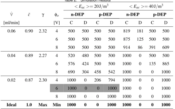
Table 2. Simulation Results
< Eac>= 20 J/m3 < E
ac>= 40 J/m3
˙∀ c¯ γ φo n-DEP p-DEP n-DEP p-DEP
[ml/min] [V] C D C D C D C D 0.06 0.90 2.32 4 500 500 500 500 819 181 500 500 6 500 500 500 500 875 125 500 500 8 500 500 500 500 914 86 391 609 0.04 0.89 2.27 4 520 480 500 500 1000 0 500 500 6 576 424 500 500 1000 0 135 865 8 690 304 458 542 1000 0 0 1000 0.02 0.87 2.30 4 1000 0 206 794 1000 0 0 1000 6 1000 0 0 1000 1000 0 0 1000 8 1000 0 0 1000 1000 0 0 1000 Ideal 1.0 Max Min 1000 0 0 1000 1000 0 0 1000
pressure was assigned. For the channel walls, no-slip boundary condition was implemented. For electric field, zero voltage was assigned for the large electrode, and prescribed voltage is defined for the smaller electrodes. All other boundaries were assigned as insulated. For the concentration field dimensionless concentra-tion was assigned as unity at the inlet for reservoir A and zero for reservoir B, impermeable wall was assigned for the channel walls, and convective flux was assigned for all outlets.
One major characteristic of the bioparticles is the size vari-ation of particles of the same kind. To resemble this, when the particles are released, the particle diameter is determined ran-domly following a Gaussian distribution (Mean: R = 5 µm, SD: 0.5 µm). Simulating the particle trajectory, the streamline tion of COMSOL was used. In each call for the streamline func-tion, the diameter of the particle was called using a MATLAB R function which generates the random data (to do this MATLAB interface of COMSOL was used). The particles were also re-leased from the upper and the lower branch of the inlet sec-tion, and the buffer solution that the particles was going to be transfered was flowed from the mid-channel at the inlet section. 1000 n-DEP and 1000 p-DEP particles were released for each run from random locations (50 set of particles were released with 20 randomly selected diameter). 500 particles were released from upper and lower branch of the inlet section. The simulations were performed on an HP Z400 Workstation (Intel Xeon W3550, Quad core, 3.06GHz, 16GB RAM). Typically, degree of freedom of the system was 960K, and the typical run-time for the simu-lation of the solution of concentration and velocity fields was around 2 mins and for the simulation of the particle trajectories of 2000 particles was around 30 seconds.
RESULTS AND DISCUSSION
The input parameters used in the numerical analysis are tab-ulated in Tab. 1. The results are summarized in Tab. 2. Typical values for water were used since the buffer solutions used in the biological applications are usually water-based. The binary dif-fusion coefficient is taken as 10−9m2/s which is a typical value for liquid solutions. To characterize the performance of the wash-ing, average dimensionless concentration ( ¯c) was computed at the channel connecting washing and separation section. To char-acterize the performance of the concentration section, the ratio of the volumetric flow rate (per unit depth) in the main chan-nel of the concentration section to the volumetric flow rate at the outlet C (γ) was computed. To characterize the performance of the separation, the number of particles collected at the reservoirs C and D (columns 5–12 in Tab. 2) was determined for different < Eac > values. Ideal case is also indicated in the last row of the table. To minimize the power consumption of the final de-vice, the voltage and the < Eac> values needs to be minimized
(one ultimate goal of the microfludics technology is to develop portable devices which favor lower power consumption).
The success of the units depends on the balance between the drag force and the DEP/acoutic forces. When flow rate is small, the particles have enough time to respond to the external force field. This can be observed clearly by looking at the case with the lowest flow rate. For the lowest flow rate, most of the cases reach the ideal case for particle numbers. However, to maximize the efficiency of the washing units, higher flow rate is better. For a lower flow rate, there is more time for diffusion of the buffer solutions. However, as seen from the second column, this issue is not a serious problem since even for the lowest flow rate average
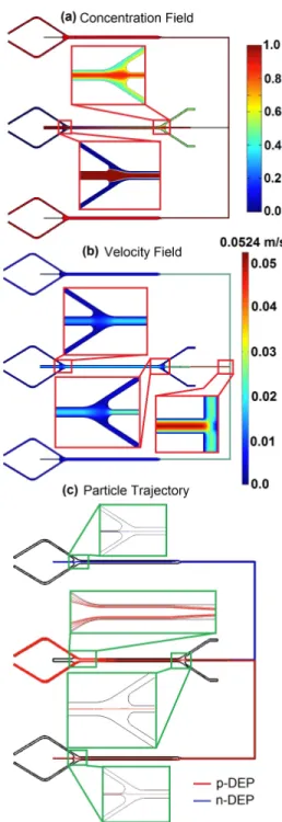
Figure 3. Simulation results for the chosen case
dimensionless concentration is 0.87 which is not much different than that of the high flow rate.
It can be observed form the table that the separation of p-DEP particles is more critical than n-p-DEP particles. The reason is that the particles need to be attracted toward the small electrodes and directed to exit D. DEP force is strong at the vicinity of the small electrodes. So, it needs to attract the particles which are
already far away from the small electrodes.
The success of the separation also depends on how well are the particles are gathered at the centerline of the microchannel in the washing unit. This can be observed by comparing the results for different < Eac> values. As < Eac> increases the acoustic
force increases meaning that regardless of the size, all particles flow at the centerline as they flow into the separation section. Therefore, with increased < Eac>, more cases reach the desired
ideal case.
As a result of these simulations, the case colored with gray is chosen for the most suitable design. If higher throughput is desired, the case with ˙∀ = 0.04 ml/min, φo= 8 V and < Eac>=
40 J/m3can be another choice, but keeping in mind that the lat-ter will have more power consumption than the former one. For the chosen case, the velocity and concentration field and the par-ticle trajectories are shown in Fig. 3. As seen from the figure, particles are collected at the centerline in the washing section, and they have changed their buffer solution. At the exit of the washing section, there exists a core where the concentration is very close to unity, and this core flows into the separation sec-tion. At the separation section, p-DEP and n-DEP particles are separated (at the washing section n-DEP particles (i.e. blue ones) cannot be seen, since the trajectories of p-DEP and n-DEP ticles are overlapped). Again in the concentration section, par-ticles are collected at the centerline, directed toward reservoir C and D, and some of the buffer solution is taken out from the side channels.
SUMMARY AND OUTLOOK
In this study, the numerical simulation of an integrated mi-crofluidic device for bioparticle wash, separation and concentra-tion is presented. The proposed device uses a hybrid approach which utilizes the strength of ultrasonic and dielectrophoretic method in different functions. Washing and concentration of bioparticles are performed by acoustophoresis and the separation is performed by dielectrophoresis. For simulating the flow within the microchannel, a computational fluid dynamics model using COMSOL Multiphysics software was implemented. To account for the size variation of the bioparticles, particles with normal size distributions were used. With a proper design, it has been shown that all three operations can be performed successfully.
These kind of simulations are very important to develop ef-ficient microfluidic devices. Point particle approach was used in the analysis. Although, point particle is a simple model, com-putationally it is very efficient as demonstrated. The success of this method has been illustrated previously for electrokinetic sys-tems. However, this study is one of the earliest efforts to use the same approach to model a system with acoustophoresis. The hy-brid use of acoustophoresis and dielectrophoresis is also very rare in the literature. It has been shown for the first time in the litera-ture that decreasing variation of particle position using ultrasonic
field before dieletrophoretic separation has positive effect on sep-aration performance. In this study, an efficient integrated mi-crofluidic system utilizing acoustic and dielectrophoretic meth-ods is demonstrated, and computationally feasible model to pre-dict the performance of the device is presented. In the next step, the fabrication and the testing of the device will be performed. In this study, waste channels placed after the washing unit have not been desinged. Prior to the fabrication, those waste sections will be designed to achieve the desired flow field at the exit of the washing section. The real device will have a channel height of 100 µm for high throughput, and for an efficient separation with DEP, 3D sidewall electrodes will be utilized. A hybrid technique composed of micro-machining and lithography will be used for the fabrication of the device.
ACKNOWLEDGMENT
Financial support from the Turkish Scientic and Technical Research Council, Grant No. 112M102, is greatly appreciated.
REFERENCES
[1] Bruus, H., 2009. Theoretical Microfluidics. Oxford Univer-sity Press, pp. 255–270.
[2] Cetin, B., and Li, D., 2011. “Dielectrophoresis in microflu-idics technology”. Electrophoresis, 32, pp. 2410–2427. [3] Wu, Z., and Hjort, K., 2009. “Microfluidic hydrodynamic
cell separation: A Review”. Micro and Nanosystems, 1(3), pp. 181–192.
[4] Lenshof, A., and Laurell, T., 2009. “Continuous separation of cells and particles in microuidic systems”. Chemical So-ciety Reviews, 39, pp. 1203–1217.
[5] Augustsson, P., Aberg, L. B., Sward-Nilsson, A.-M. K., and Laurell, T., 2009. “Buffer medium exchange in continuous cell and particle streams using ultrasonic standing wave fo-cusing”. Microchim Acta, 164, pp. 269–277.
[6] Leal, L. G., 2006. Advanced Transport Phenomena: Fluid Mechanics and Convective Transport Processes. Artech House, pp. 164–168.
[7] Kang, K. H., Xuan, X., Kang, Y., and Li, D., 2006. “Ef-fects of DC-dielectrophoretic force on particle trajectories in microchannels”. J. Applied Physics, 99(064702), pp. 1–8.