22.7
SMART RADOME IMPROVE§ REFLECTOR ANTENNA DIRECTIVITY
Ayhan Altinta?’) Vladimir YurchenkolJ) and Alexander Nosich2) Electrical and Electronics Engineering Dept, Bilkent Universit?
Bilkent, Ankara 06.533, Turkey
tel: $90-312-266-4000( 1489), fax: $90-312-266-4307 e-mail: altintasQee.bi1kent.edu.tr
’) Institute of Radiophysics and Electronics. K.-\S of Ukraine Ulitsa Proskury 12, Kharkov 310083: Vkraine
1. I n t r o d u c t i o n
To ensure protection from dust: wind. rain and snow. reflector antennas are covered with spherical dielectric radomes. However. normally it is considered that the presence of the radome in the near zone of reflector is a negative factor in electromagnetic sense. Antenna performance suffers: main beam is typically distorted, sidelobe level get higher, and overall performance. first of all direc- tivity. is lost [l]. In part, this is due t o the fact t1ia.t such antenna systems are not designed in a self-consistent manner. by taking fully into account all the interactions between the elements. In this paper. we dem0nstrat.e that an accurate numerical optimization procedure can bring a different vision of this situation. By a clever play with the radome thickness, its radius. the reflector location inside the radome, and the position of the feed. one can improve an- tenna performance with respect to the free-space reflector. To reach this goal. the optimization code must be based on solving a rigorous integral equation b>- means of the regularization technique, guaranteeing a desired accuracy.
2. F o r m u l a t i o n a n d Solution
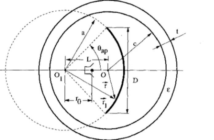
Consider a 2-D model of cylindrical reflector antenna (Figure 1 ) arbitrarilj- located inside a circular cylindrical dielectric radome. The feed is assumed t o be complex-point line source radiating a directive incident beam. The width of the latter is determined by the imaginary part of the source coordinate. xliich simula.tes the aperture width of a. real horn feed.
lye start our analysis with an electric-field integral equation obtained from the PEC boundary condition on the contour
JI
of the reflector (H-polarization):where j ( r < ) is the current densit.? t o be found. E’” is the incident complex-point source field. li is the outer unit normal vector. and G is the Green‘s function of 0-7803-4178-3/97/$10.00
0
1997IEEE
Figure 1: Geometry of the reflector in the radome
the circular dielectric shell. So, the latter function takes into account rigorously the geometry and material parameters of the radome including the cuivatuie effect, creeping waves and possible resonances.
In the case of a circular radome, the function G has an analytical form obtained by using the addition theorems for the cylindrical functions:
cn
G(ri,G) = Go(ri,G) - ~ ~ < n J p - n ( k ~ ) J ~ - n ( k J ) J ~ ( ~ r * ) J ~ ( k r ~ ) e z ( ~ ~ l - ~ p ~ ) 4
n,p,l=-CC
(2) where Go =
the coefficients accounting for presence of the radome.
Hjl'(klri
-4
I)
is the 2-D free-space Green's function, andli,
areFurther we follow [2] and solve (1) by the regularization method. To avoid the numerical integrations for filling in the matrix of the resulting equations, we simulate the geometry of a parabolic reflector by a circular one. This ap- proximation is known to be acceptable if the geometries are chosen such that the electrical error does not exceed 1/16-th of the wavelength 131. It enables us to convert (1) t o a discrete form through the so-called dual-series equations in terms of the surface current expansion coefficients z, as in [2]:
03 m
[ z , ~ ? ) ' ( k a )
-
yn] JA(ka)etnp1 = - bnez"pl., v1
E M (3)n=-m ,=-cc
where
CO
b, = J,(lcr,l)H~')'(ka)e-"nBI - ~ L ( k a ) Ji(kTsl)e-i'8*Lin
l=-m
Regularization of these equations is based on the analytical inversion of the static part. Solving the resulting matrix equation is remarkably stable and always convergent t o the exact solution with a greater number of equations. However, a special care should be taken for numerical summation of the Bessel function series (such as in (2)).
3. Numerical Results and Conclusions
A well-known recommendation based on the plane wave - flat slab analysis is t o take the radome thickness as 1 / 2 of the wavelength in the radome material A, = X O / ~ ? . However, in reality neither the radome is flat nor the radiation field is a plane wave. The presence of a curved PEC strip inside the radome is an additional reason of a more complicated scattering. This is especially impor- tant for smaller radomes. Full-wave analysis by solving (1) shows that the actual optimum thickness yielding a maximum directivity is shifted t o the smaller value.
28.5 28 27.5 27 26.5 26 c .- 2 a, 0
-
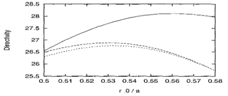
0 ._ 25.5 0.5 0.51 0.52 0.53 0.54 0.55 0.56 0.57 0.58 r-0 I aFigure 2: Directivity as a function of the feeder position for the reflector in free space (dotted curve), in the radome of the 'rule-of-thumb'parameters (dashed curve, t = O.5Xc, L = a cos(B,,) = 4.330A0, c = 6x0) and in the fully-optimized radome/reflector system referred to Figure 1 are a = 5 x 0 , B,, = 30" ( D = 5X0), k b = 2.6 (edge illuniiiiation (solld curve, t 0 341X,, L = 4.271X0, c = 5.984Xo). The other relevant parameters -lo&), t, = 2 .
If the thickness has been optimized, then varying the radome radius and the reflector position has a smaller effect on the directivity. However, the feed po- sition should be corrected with respect to the free-space optimum after finding the best thickness (Figure 2).
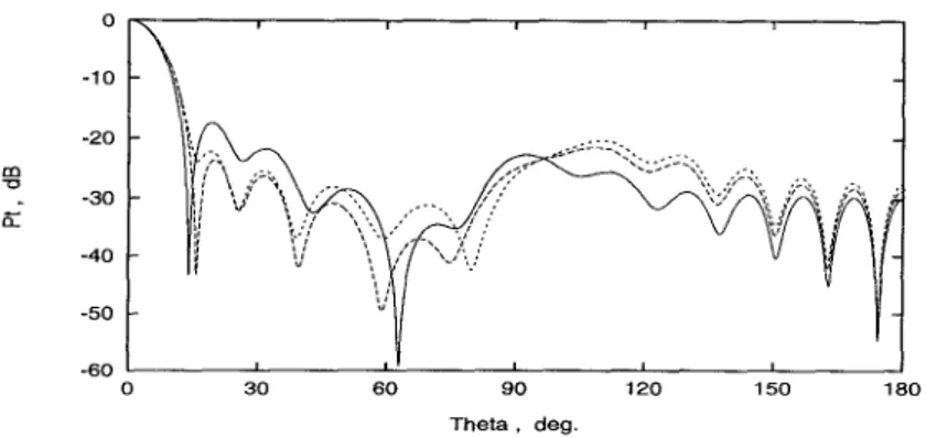
In Figure 3, we compare two free-space radiation patterns (for non-optimized in-GO-focus feed, and for the optimized one) with a pattern for the completely optimized reflector-in-radome antenna system. One may see that the improve- ment of the directivity is obtained a t the expense of the first sidelobe level.
0 -1 0 -20
B
-30 K -40 -50 -60 0 30 60 90 120 150 180 Theta, degFigure 3: Far-field patterns of the reflector in free space ( Y o = 0.5a, dotted curve, and
TO = 0.533a, dashed curve), and of the optimum radomelreflector system (solid curve). A set of 50 equations taken; CPU time is 3 seclcurve with SUNSPARC Station 20.
._
.... ,6 23 23
21 21
0 0.2 0.4 0.6 0.8 1 3 3.5 4 4.5 5
t l X , LIXo
Figure 4: Directivity as a function of the radome (a) thickness and (b) shift in the optimum system ( T O = 0.560a, solid curve) and in the 'rule-of-thumb' radome with
feeder position T o = 0.533a (dashed curve) and T O = 0 . 5 ~ (dotted curve). The other
relevant parameters are the same as in Figure 2.
Figure 4 gives a vision of the dependence of the directivity on the radome thickness and the reflector location.
Summarizing, we state that the solution obtained can be efficiently used in the numerical antenna optimization code.
References
[1] J.-H. Chang, K.-K. Chan, Analysis of a two-dimensional radome of arbi- trary curved surface, IEEE Trans. Antennas Propagat., vol. 38, no 10, pp.1565- 1568, 1990.
[2] T. Oguzer, A . Altintas, A. I. Nosich, Accurate simulation of reflector antennas by the complex source - dual series approach, IEEE Trans. Antennas Propagat., vol. 43. no 8, pp. 793-801, 1995.
[3] J. D. Kraus, Antennas, New York: McGrow-Hill, 1988.


