Research
Performance comparison of ASN.1
encoder/decoders using FTAM
Murat Bilgic* and Behcet Sarikayat
Abstract Syntax Notation-One (ASN. l) is a standard external data representation language used to define messages of application layer protocols. Its encoding rules, the Basic Encoding Rules (BER), are also international standards that define the encoding/decoding of data values into/from a transfer syntax. Various approaches to automating BER encoding/decoding are examined; in particular, two widely used software packages (ISODE and CASNl) are studied. A hardware BER encoder/decoder called VASNl is presented. Performance of software and hardware approaches are evaluated on real instances of file transfer using a standard FfAM protocol. Benchmarks obtained from running CASNl on one of the fastest workstations and from running VHDL simulations of VASNI indicate the superiority of the hardware approach.
Keywords: ASN.l, Basic Encoding Rules, ISODE, CASNl, VASNI, benchmarks, FTAM
Open systems interconnection (OSI) protocol standards ,have been developed to achieve the interconnection of systems from different vendors. However, there is growing concern as to whether the performance of implementations of these protocols can be good enough to meet end-to-end delay and throughput requirements. With advances in high-speed networks, a large difference between the performance at the application layer and the signalling rate of networks is becoming more apparent, since performance is mainly limited by the speed of computers which process the incoming and outgoing messages1. There have been different approaches to identify the possible locations of the bottleneck. Some researchers suggest that *Concordia University. Department of Electrical and Computer Eng111eering. 1455 de Maisonneuve W. #915. Montreal. Quebec. �anada H3G I MS
Computer Engineering and Information Sciences Department. Btlkcnt University. Bilkent. Ankara 06533. Turkey (email: sarikaya �' trhtlun.hitnet)
Paper rccC'ived: 30 Seplemhff 1991: revised paper received: 4 Decemhff /99/
protocols are to be blamed, and new protocols that can be computed by hardware in special chips should be developed2. Others claim that the implementations of the protocols are to be blamed, and it is possible to obtain high throughput with more efficient implementa tion3. It should also be noted that much of the continuing research is located at the transport layer and below. However, especially for OSI application services, a large part of the execution time is spent in the layers above the transport layer4. One of the major contributions of this part is the data encoding/ decoding, which is a natural requirement of hetero geneous networks.
The lower five layers of the OSI model deal with the movement of bits from source to destination, whereas the functionality of the sixth layer - the presentation layer - is to preserve the meaning of the information exchanged. Since the main motivation behind the OSI model is to achieve reliable communication in a heterogeneous environment, where different computers, different operating systems, etc., are involved, the model should provide some mechanism to convert the machine-dependent data structures into a bit stream suitable for transfer by the lower layers, and then to decode it to the required representation at the destination.
To solve the problem of representing, encoding, decoding and transferring complex data structures, a standard notation called Abstract Syntax Notation One (ASN.1)5 has been defined. Along with the notation, a set of encoding rules called Basic Encoding Rules (BER)6, used to perform conversion between the data values and the transmitted bit stream, has been introduced. The format of the bit stream is called the
transfer syntax.
In this paper, we compare the performance of our VLSI-based ASN.l (VASNl) encoder/decoder with that of two different software-based implementations on Protocol Data Units (POU) exchanged between two File Transfer Access Management (FTAM) entities. 0140-3664/93/040229-12 © 1993 Butterworth-Heinemann Ltd
Performance of ASN.1 encoders/decoders: M Bilgic and B Sarikaya ASN.1
Data structures
In the OSI stack, the nature of the data exchanged between two communicating entities substantially changes when the session layer-presentation layer boundary is crossed. In session and lower layers, PD Us are specified informally with the help of illustrations. These PDUs are considered as a flat sequence of octets. Presentation and application PDUs (PPDUs and APDUs) necessitate a more formal method for describing data structures. Because of this necessity, ASN. l is proposed to describe the semantics of PD Us independent of the particular programming language, compiler or operating system being used on any node of the heterogeneous network. Since such networks include different types of machines, the representation of simple data (e.g. integer, boolean, etc.) should also be standardized to enable such machines to communicate. A common set of encoding rules understood by all the nodes of a heterogeneous network must be provided to convert the values of PDUs in their local format to/ from a transmitted bit stream.
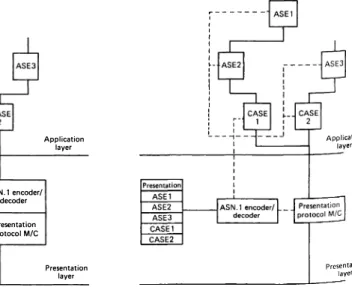
Application layer entities, unlike other OSI layer entities, are not self-contained entities; instead, they are collections of Application Service Elements (ASE), and Common AS Es (CASE). Each ASE cooperates with its peer using a specific protocol, and the set of ASEs within the application layer entity is determined by the application context. An application service is provided by a dynamic stack of ASEs and a presentation layer entity. One example is a FTAM Service Element, which uses the Association Control Service Element (ACSE) only for setting up and finishing an association. After association, FTAM ASE directly connects to the presentation layer entity.
Although ASN. l encoding/decoding is conceptually associated with the presentation layer. an ASN. l encoder/decoder can be implemented so that it
Figure I Structure of Application and Presentation layers. (a) ASN.I encoder/decoder inside the Presentation Layer: (h) ASN. I encoder/ decoder outside the Presentation Layer
provides an ASN. l encoding/decoding service to AS Es. CASEs, and the presentation layer itself, as shown in
Figure 1 b. Such a layerless ASN. l encoder/decoder can
be implemented with special hardware support to provide a much faster encoding/decoding service, which is particularly required in high-speed networks.
Abstract syntax
Basic concepts of ASN.1 are types and values. A subtype is a type which is a subset of another type. ASN. l provides a number of built-in types as well as a number of tools with which constructed types can be defined. There are two kinds of tool: type constructors, which are used to define types that include values of other types;
and subtype constructors, which are used to define types
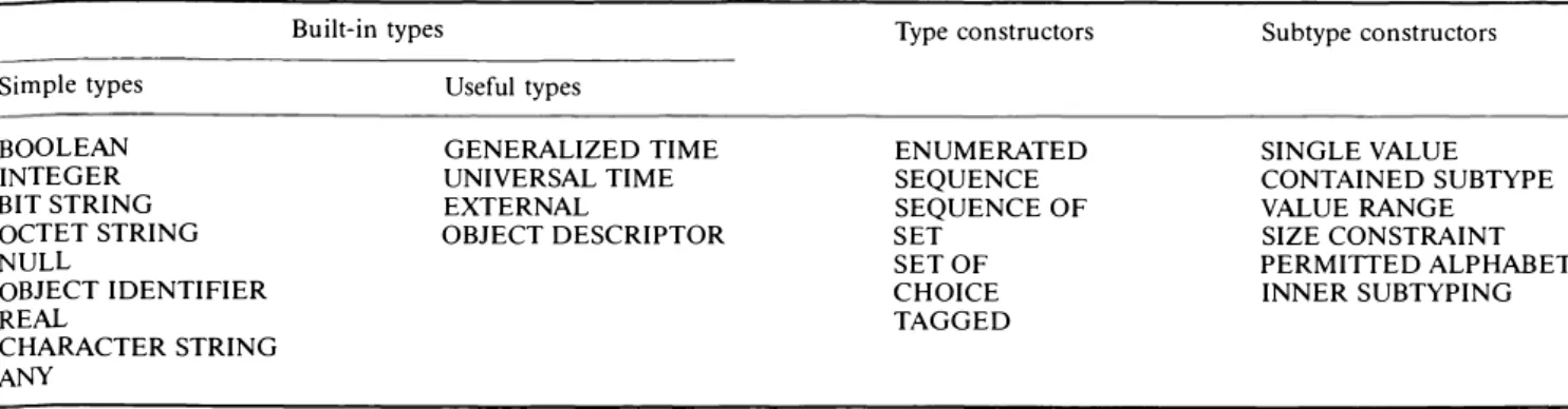
that include only a subset of the values of another, parent type. The types and constructor tools of ASN. l are listed in Table 1. ASN.1 is a case sensitive language with most of its keywords (BOOLEAN, ENUMERATED) written in capitals.
Simple built-in types are notationally integral to
ASN.1, whereas useful built-in types are defined by means of type constructors. Some of the simple built-in types (e.g. BOOLEAN, INTEGER, REAL) are similar to those found in any programming language. BIT STRING and OCTET STRING are variable length strings of bits and bytes, respectively. The NULL type comprises a single value NULL the OBJECT IDENTIFIER type is used to name standard and user defined information object classes. There are several CHARACTER STRING types which comprise the ordered sequence of variable numbers of characters. The ANY type can be considered as the union of all types. GENERALIZED TIME and UNIVERSAL TIME types are used to identify time points. The EXTERNAL type constitutes the instances of informa tion object classes, and the OBJECT DESCRIPTOR type is used to show the textual descriptions of those classes. ASN. 1 encoder/ decoder Presentation protocol M/C Application layer Presentation layer r---• Application layer Presentation layer
Performance of ASN.1 encoders/decoders: M Bilgic and B Sarikaya
Table 1 ASN.l types and constructor tools
Built-in types Simple types BOOLEAN INTEGER BIT STRING OCTET STRING NULL OBJECT IDENTIFIER REAL CHARACTER STRING ANY Useful types GENERALIZED TIME UNIVERSAL TIME EXTERNAL OBJECT DESCRIPTOR
An example ASN. l module is given in Figure 2 to better describe the use of ASN. l.
The ENUMERATED type constructor is used to define named integers; the SEQUENCE type constructor is used to define a type such as Type A of Figure 2. whose values are ordered collections of values (e.g. first and second are similar to record structures in pro gramming languages); the SET type constructor is used when the order of components of a record is not important. A component of SET or SEQUENCE, such as the component first of Type A, may be declared as OPTIONAL whose value need not be present in the record, or as DEFAULT, with a default value as in the case of component s2 of Type C, whose default value is 1. The SEQUENCE OF and SET OF type constructors are used to define types, e.g. Exp-PDU, Type B of
Figure 2. whose values are collections of homogeneous
values similar to arrays in programming languages. The CHOICE type constructor is used to define a type that is the union of one or more alternative types with distinct tags similar to variant records. The TAGGED type constructor is used to define a type that differs from a specified subject type only by its tag.
Each ASN. l type is associated with a tag. The tag mechanism is used to provide a basis for distinguishing values of one type from those of others (as well as the TAGGED type constructor). A tag has two parts; its class and number. A tag's class specifies the domain of its number. UNIVERSAL tags are defined exclusively in the ASN.1 standard for types such as Type A, which is of the SEQUENCE type and has a tag UNIVERSAL 16. APPLICATION tags are defined for each ASN.1 module which is a named package for related definitions
EXAMPLE DEFINITIONS::=
BEGIN
Exp-PDU ::= IAPPLICATION O] IMPLICIT SEQUENCE OF TypcA
TypcA: = SEQUENCE j first IOI IMPLICIT TypcB OPTIONAL.
second Ill IMPLICIT TypcCf TypcB := SET SIZE (2) OF INTEGER
TypcC ::= SEQUENCEjsl IA5String.
s2 INTEGER DEFAULT If END
Figure 2 Example ASN. l module
Type constructors ENUMERATED SEQUENCE SEQUENCE OF SET SET OF CHOICE TAGGED Subtype constructors SINGLE VALUE CONTAINED SUBTYPE VALUE RANGE SIZE CONSTRAINT PERMITTED ALPHABET INNER SUBTYPING
of types and values. PRIVATE tags are for user-defined data types, and CONTEXT-SPECIFIC tags vary from one context to another formed by the alternative CHOICE type, or the element type of a SEQUENCE or SET type. As an example, in Figure 2 the components first and second constitute different contexts within Type A, and they differ with their tag numbers.
Tran sf er syntax
Encoding rules define a transfer syntax for values, allowing them to be exchanged between open systems. Different transfer syntaxes (in turn, different encoding rules) may be needed at different times for the same abstract syntax, for different purposes.
BER are currently the only standard encoding rules. They provide a transfer syntax where encoding of every value has three parts: the identifier, length, and contents octets. If length octets use a specific format, called indefinite. then another part, called end-of contents, succeeds the contents octets.
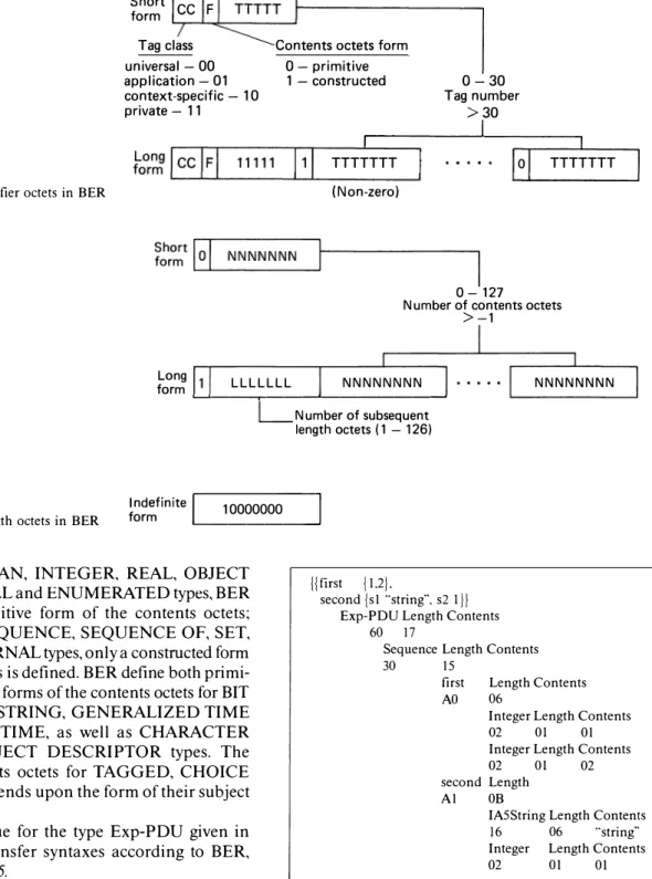
The identifier octets encode the value's tag and form. They take either the short form, comprising a single octet for types with tag numbers up to 30, or the long form, comprising two or more octets for types with tag numbers 31 and greater, as shown in Figure 3.
The length octets, which indicate how the final octet of the encoding is located, take one of three forms: short, long, or indefinite. The short form, comprising a single octet, is used to encode the number of contents octets, which is up to 127. The long form consists of two or more octets, where the first octet shows the number of succeeding length octets that encode the number of contents octets up to l1°08 - 1. The indefinite form,
using a single, fixed octet indicating the presence of end-of-contents-octets (two 'OO'H octets), may only be used for a constructed form of the contents octets (see
Figure4).
The contents octets take either primitive or constructed form. The primitive form consists of zero or more octets whose meaning depends on the type of the encoded value. The constructed form consists of the encodings of zero or more other values whose meaning depends on the type being encoded.
Performance of ASN.1 encoders/decoders: M Bilgic and B Sarikaya
Figure 3 Identifier octets in BER
Short CC F form Tag class universal -00 application -01 context-specific -10 private -11
Contents octets form 0 -primitive 1 -constructed TTTTTTT (Non-zero) 0-30 Tag number >30
I
0-127 TTTTTTTNumber of contents octets >-1 Long form
'---'---.---'---�
LLLLLLL NNNNNNNN NNNNNNNN 10000000 Number of subsequent length octets (1 -126)Figure 4 Length octets in BER
Indefinite
I
form ...._
_____
___.For the BOOLEAN, INTEGER, REAL, OBJECT IDENTIFIER, NULL and ENUMERATED types, BER define only a primitive form of the contents octets; whereas for the SEQUENCE, SEQUENCE OF, SET, SET OF and EXTERNAL types, only a constructed form of the contents octets is defined. BER define both primi tive and constructed forms of the contents octets for BIT STRING, OCTET STRING, GENERALIZED TIME and UNIVERSAL TIME, as well as CHARACTER STRING and OBJECT DESCRIPTOR types. The form of the contents octets for TAGGED, CHOICE and ANY types depends upon the form of their subject types.
An example value for the type Exp-POU given in
Figure 2, and its transfer syntaxes according to BER,
are given in Figure 5.
SOFTWARE IMPLEMENTATIONS
Several software tools such as compilers 7, libraries inside communication software packages8 and trans lators9 have been developed to support ASN.1. In this
section we discuss two of them.
CASNl
CASNl is an ASN.1-C compiler, along with an implementation of BER, called the ED library, which
jjfirst jU}.
second {sl ""string··. s2 1/} Exp-POU Length Contents
60 17
Sequence Length Contents 30 15
first Length Contents AO 06
Integer Length Contents
02 01 01
Integer Length Contents
02 OJ 02
second Length Al OB
IA5String Length Contents 16 06 ""string·· Integer Length Contents
02 OJ OJ
Figure 5 Value of Exp-POU and its transfer syntax
has been developed at the University of British Columbia 7. The approach of CASNI is the most direct approach to encoding/decoding data with no type information embedded. It provides the application a comprehensive set of procedures to encode/decode every elementary item in the abstract syntax. The primary design goal in this project is to obtain efficient encoder/decoders by eliminating the use of an inter mediate form, and by building a specialized memory management system.
Performance of ASN.1 encoders/decoders: M Bilgic and B Sarikaya
The ED library contains four classes of routines. Primitive class routines are the encoding/decoding routines for ASN.l types BOOLEAN, INTEGER, BIT STRING, OCTET STRING, NULL, OBJECT IDENTI FIER, UNIVERSAL TIME, GENERALIZED TIME and EXTERNAL. Constructor class routines are specific routines to encode/decode struct_beg and
struct_end. which enclave the encode/decode routines
for components of the constructed type. Utility class routines are used to encode/decode tags, end-of contents, manipulate the tags, move value from files into main memory, and serialize an IDX link list, whose structure is given in Figure 6, and generate a flat octet sequence. IDX structure is used to store the output of each encoding routine. This serialization step usually takes most of the total encoding time when long PD Us are processed. Memory class routines are used to
manage the ED library sub-memory system.
!SODE
The ISO Development Environment (ISODE) is a software package developed by the Wollongong Group and the Northrop Corporation for OSI-based applica tions 8. As part of its structure, the I SODE contains a set of ASN. l tools and libraries. The main design objective of this project is to provide BER encoding/decoding to different ASEs existing in the ISODE.
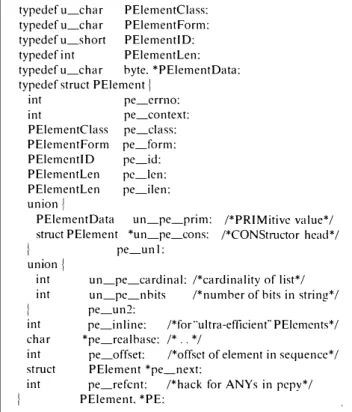
It has a library called 'libpsap' which implements present�tion layer abstract-syntax for the machine independent exchange of data structures. It uses two objects, presentation-elements (PE) (whose structure is shown in Figure 7) and presentation-streams (PS). PE is an internal form used to represent ASN. l objects in a machine-independent form. There are several library routines which convert a PE into machine-dependent types in the C lari°guage. PS is an object used to represent an 1/0 path of a PE, such as a communication port or a file pointer.
Encoding/decoding routines are produced by the
pepy program from the augmented ASN. l specifications,
which are produced by another program called posy from the original ASN. l specifications. The posy program also produces a set of C structures for the corresponding ASN. l types.
The output octet sequence of each encoding routine is stored in a PE whose structure is suitable to embed PDUs from different layers and/or ASEs. Similar to
typedef unsigned char byte: typedef struct !DX j
byte *buf: /*pointer to an octet string*/ long len: /*length of the octet string buf*/ struct !DX *next : /*pointer tonext !DX node*/
IDX. *ptrlDX:
Figure 6 C structure !DX definition
typedef u_char PElementClass: typedefu_char PElementForm: typedefu_short PElementID: typedef int PElementLen: typedefu_char byte. *PElementData: typedef struct PElemcnt j
int pe_crrno: int pe_context: PElementClass pe_class: PElementForm pe_form: PElemcntID pc_id: PElementLen pc_len: PElementLen pe_ilen: union
l
PElementData un_pe_prim: struct PE!ement *un_pe_cons:f pe_unl:
/*PRIMitivc value*/ /*CONStmctor head*/ union j
int un_pe_cardinal: /*cardinality of list*/ int
f
int char int struct intun_pe_nbits /*number of hits in string*/ pe_un:2:
pe_inline: /*for ··ultra-efficient"' PElcmcnts*/ *pe_rcalhase: /* .. */
pe_offset: /*offset of element in sequence*/ PE!ement *pe_next:
pe_refcnt: /*hack for ANYs in pcpy*/ PElement. *PE:
Figure 7 C structure PE definition
CASNI, PE needs to be serialized into a continuous octet string and this step usually takes most of the time for encoding long PDUs.
VASNl
The basic idea behind the design of a VLSI-based ASN.l (VASNI) encoder/decoder is to achieve fast encoding/decoding by mapping concurrent algorithms developed within the same project to a specialized hardware. Since an ASN. l encoder/decoder is expected to function in a heterogeneous environment (e.g. different abstract and/or transfer syntaxes, different types of host machines, etc.), it should be flexible enough to accommodate changes. Since VLSI is selected as the implementation medium, the design should be regular enough such that it can be constructed using a number of basic building blocks.
Model
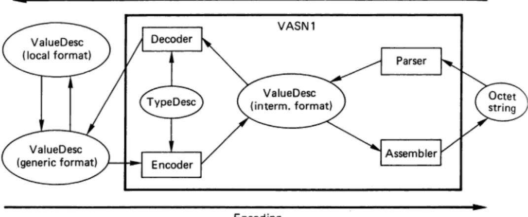
As shown in Figure 8. VASNI is composed of several modules. Parser and assembler modules perform the conversion between the BER encoded octet string and the Value Descriptions in an intermediate format. The decoder module takes these Value Descriptions and the static Type Descriptions for the current abstract syntax and generates the generic format Value Descrip tions. In this form, the incoming octet sequences a.re
Performance of ASN.1 encoders/decoders: M Bilgic and B Sarikaya
Figure 8 Conceptual model for ASN.l encoding/decoding
ValueDesc ( local format)
ValueDesc (generic format)
replaced with the values of corresponding types. The generation of the Value Descriptions in the desired local format, (e.g. C, Pascal data structures) is left as a user option, depending on the environment. The
encoding process is the dual of the decoding process. The static Type Descriptions for each abstract syntax are produced from their ASN. l definitions by a software tool developed from the CASNl compiler.
Architecture
VASNl is designed to be implemented with VLSI
technology. To reach a modular and simple design, different functional blocks are implemented on the same type of module. Basically, the parser and assembler pair and the encoder and decoder pair are implemented on two identical modules, as shown in
Figure 9. The two modules and an intermediate buffer
between them are connected through a local bus. The parser/assembler and encoder/decoder modules are also connected to the system bus to communicate with the master host, and to input from/output to the main memory.
To reach a regular, simple and efficient design, operating system functionalities are excluded from the execution units (EU) of the basic module. Instead, a processor is assigned with the task of distributing the load among the EUs. However, regularity is preserved, since both the central controller (CC) and EUs are implemented using the same RISC processor. There is
Local bus
i
t
t
Host memory Main Parser
Buffer Encoder
assembler decoder
i
i
System bus
Figure 9 Organization of basic modules
Decoding
VASN1
Encoding
no communication between the EUs, but the CC communicates with the EUs through the local module bus in terms of messages (see Figure 10). Another RISC called the interface controller (IC) is used to serve the execution units for memory read/write operations. The same module bus is used for communication between the EUs and the CC and IC.
The messages originated in the EUs are put into I/0 registers, and the destination processor is signalled via an interrupt to complete the transfer by reading the I/0 registers. Then the EU resumes its operation until a synchronization point comes in the program, in which case it simply polls the I/0 register for the incoming message from the source processor. The communication in this direction is initialized by either the CC or the IC, which writes to the I/0 registers of the destination EU. The CC and IC share the bus between them through an arbiter.
The RISC processor and other satellite units ( e.g. I/0 register, bus arbiters, local memory modules for RISCs) are developed using 1.2-micron CMOS technology. The RISC processor is a 16 bit machine whose instruction set covers 16 instructions. All the instructions
-System bus
-i
Local bus1
Processor -~ Processor Bus(cen. ctl.) --- arbiter --- (bus I
-...
interface) I I I I•
-
1
Module bus1
-1/0 reg. 1/0 reg. 1/0 reg. 1/0 reg.
t
t
Processor Processor Processor Processor
(exe. un. 1) (exe. un. 2)
-
(exe. un. 3) (exe. un. 4)Figure 10 Module with four EUs
Performance of ASN.1 encoders/decoders: M Bilgic and B Sarikaya
except those related to memory transfer take I cycle. The clock rate of the RISC is chosen to be 8 MHz (divided into four subcycles). All the instructions except store, load, jump, call and return are pipelined, increasing the effective clock speed to around 32 MHz. Each processor has local RAM and ROM of 2 Keach, as well as 16 registers. The local ROM is used as the instruction memory for each processor.
VASNl is designed with each module containing six RISCs running either parser/assembler or encoder/ decoder software packaged into a single chip. The two modules are connected to standard memory units, which constitute the last component of the VASNl system. The VASNI system is designed to be embedded into any host system 10.
VASN 1 software
The following sections briefly present the algorithms used in VASNI.
Parsing phase
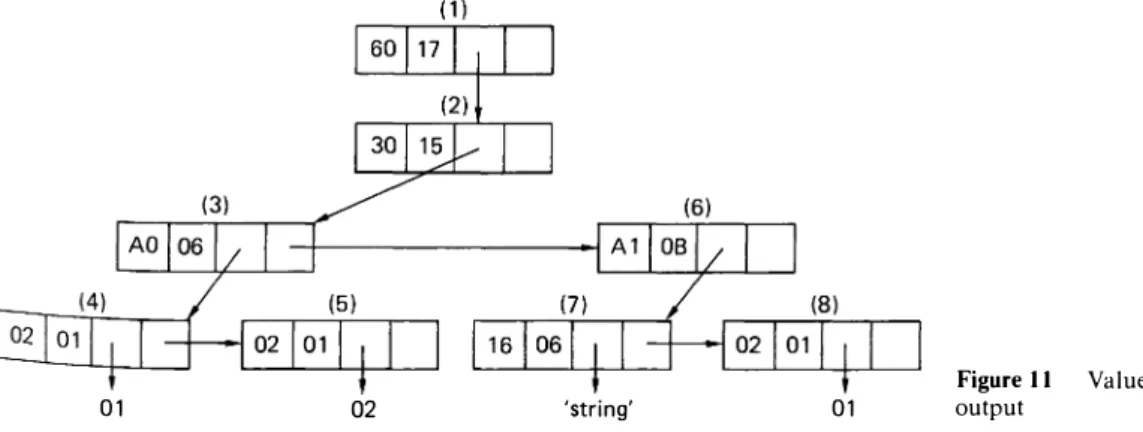
The most important characteristic of BER encoded strings is that they can be separated into or constructed from the identifier, length and contents octets inde pendently of the abstract syntax. In other words, a given BER encoded string w can be converted into a value tree
T,. whose intermediate nodes contain only the identifier
and length octets, whereas the leaf nodes also contain the contents octets for the primitive encoded types.
An example input to the parser is shown in Figure 5. The output of the parser is the value tree shown in
Figure I 1.
Now let us describe the possible degree of con currency in the conversion of a BER encoded string into its value tree. According to BER, a given string w can be written as w1w2 .. wn, where:
W; = ( �d;. len; if id; is_ constructed
� id;. !en;. cnt; otherwise
Then parsing of w becomes such that P(w) = P(wi)
P( w2) .. P(wn), whereP(w;)'s take place in the execution
01 02 'string'
units of the parsing/assembling module. Parsing is initiated by the host, which sends a request message to the central controller of the parsing/assembling module. The central controller initiates the execution unit-I to process the substring w1. For the given example,
execution unit-I performs the parsing of w1, w2 and w3;
and when it finishes P(w3), it sends the address of w6 to the central controller, since the length of
I
w4w5I
isobtained during P( w3). Then, execution unit-I resumes the parsing of w4 and w5, whereas execution unit-2, initiated by the central controller, performs the parsing of w6, w7 and w8. Parsing finishes when all the
execution units become idle again.
Decoding phase
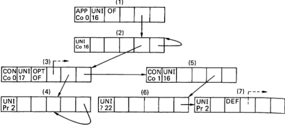
Decoding of BER-encoded ASN.1 values is performed while each node of the Value Descriptions is linked to a corresponding node of the Type Descriptions for the current abstract syntax. Type Descriptions are directly produced from the given ASN.l source text in a tree like format. The nodes of the Type Descriptions are 4-tuples <id, imp!. flags. extinf), where id constitutes the class, encoding form, and the tag number, imp! constitutes the id of its implicit type for IMPLICIT defined types,flags are set for OPTIONAL or DEFAULT components, and CHOICE, and repetitive types (e.g. SEQUENCE OF, SET OF), and extinfstores a pointer to an extra-information table that stores information such as default and enumerated values, or constraints due to subtyping. To better describe the structure of the resulting Type Descriptions, that of Exp-PDU given in
Figure 2 is shown in Figure I 2.
During the decoding operation, the value tree is traversed according to the structure of its Type Descriptions. For each node of the value tree, there must be a corresponding node in its Type Descriptions. ASN.l includes provisions such as: CHOICE, ANY, which necessitate decisions to select alternatives; OPTIONAL, DEFAULT, which necessitate decisions to omit or include such a component; and SEQUENCE OF and SET OF type constructs, which necessitate decisions to determine the end of a repeating type. Therefore, traversal of a value tree is realized by finding the matching node of its Type Descriptions for each
01 output Figure 11 Value tree of Exp-POU - parsing
Performance of ASN.1 encoders/decoders: M Bilgic and B Sarikaya
Figure 12 Type descriptions of Exp-PDU
CON UNI OPT
CoO 17 OF UNI Pr 2
node. This matching is performed by comparing the id parts of nodes of the value tree and Type Descriptions. The traversal starts with the root nodes of value tree Tv and Type Descriptions G1; and it results in another tree
T" whose nodes are produced from the fields of the matching nodes of the value tree and Type Descriptions. The resulting tree of the traversal on Tv given in
Figure I I is shown in Figure I 3. (To make the figure simpler, instead of their individual fields, node numbers for nodes of Tv and G1 are given.)
As can be seen from Figure 13, the nodes of T, for primitive types such as BOOLEAN, INTEGER OBJECT IDENTIFIER, etc., contain the decoded form of incoming octet strings, whereas the nodes for con structors such as SEQUENCE, SET, etc., have only fields of nodes of Tv and G1•
Now, let us describe the possible degree of con currency in the decoding process. Both Tv and G1, and
recursively Tv./s, G1Js, can be written as nv.root Tv. I Tv.2 .. Tv.p and nuoot G1.1 G1.2 .. Gr.q. Then decoding of Tv becomes such that D(Tv,G1) = D(nv.root,G1)D(Tv.1,G1)D(Tv.2,G1) .. D(Tv.p• G1 ), where D(Tv.;,G1 )'s take place in the execution units of the encoding/decoding module. Decoding is initiated by the central controller of the parser/ assembler module, which sends a request message to the central controller of the encoding/decoding module. The central controller initiates the execution unit- I to process the node nv.root· For the given example, decoding of nodes 1 to 3 of Tv in Figure 11 is performed by the execution unit- I. Once the decoding of nv.J is finished, nv.6 and n1.s of Figure 12 are sent to the central controller. Then execution unit- I resumes the decoding
Figure 13 Value tree T,. of Exp-PDU - decoding output 4 ( 1) APP UNI OF Co O 16 UNI Co 16 (7) r----DEF
of nv.4 and nv.s, whereas execution unit-2 initiated by the central controller performs the decoding of nv.6, nv.? and nv.8·
Encoding and assembling phases
The encoding operation is basically the inverse of decoding, where the inputs are T, and G1 and the output
becomes Tv.
Similar to the duality between decoding and encoding. there exists a duality between parsing and assembling in which the output flat octet sequence is generated from the value tree Tv. This step is the same as the serialization oflDX in CASNI, or the conversion of PE into PS in ISODE.
CC and IC software
CC units perform all the operating system function alities of the system such as distribution of the processing load for each phase of encoding/decoding among EUs, message-based communication between modules and with the host machine, as well as management of the two-directional pipeline. The CC software enables the processing of multiple PDUs at the same module by appending a PDU identifier to messages transferred to and from the EUs.
The maximum number of PD Us which can be active in a module is equal to the number of EUs, which is four for the current model. To balance the load of the module's EUs, the CC distributes the processing load of each active PDU in a different order.
IC units facilitate the memory transfer between EUs and the memory modules. They segment the
Performance of ASN.1 encoders/decoders: M Bilgic and B Sarikaya
memory into pages which are assigned to different PDUs in the pipeline. These PDUs are distinguished by their unique identifiers.
PERFORMANCE EVALUATION
The simplest approach to evaluate the performance of an ASN. l encoder/decoder is to use different types and sizes of value trees as data, and measure the time taken for encoding/decoding. The number of levels of the value tree and the number of leaves at a level can be used as parameters of the measurements. Such an approach is used by Nakawaji et al. 11 to evaluate the performance of a software-based ASN. l tool. However, a more realistic analysis can only be performed with real-time data.
To evaluate the performance of the encoders/ decoders introduced, the PDUs transferred during the use of the FTAM service of ISODE are used. These PDUs include FTAM PD Us, ACSE PD Us used during the connection establishment and release, as well as Presentation PDUs used to carry these APDUs.
FTAM is an application layer protocol for trans ferring, accessing and managing files between open systems. FTAM is connection-oriented with a series of embedded regimes: FTAM Association, file selection, file open and data transfer. Figure 14 shows the protocol stack formed during the FTAM association regime. In this figure, exchanged PDUs are given in parentheses under the used service primitives. Service primitives and PDUs written in italics are used during the association release, whereas the others are used during association establishment. In other regimes, the FTAM ASEs directly communicate with the underlying Presentation entity.
The performance of CASNl, ISODE and VASNl are measured on FTAM, ACSE and presentation PDUs generated during the use of the FTAM1 service from the ISO DE software distribution package (release
F�M �AM
-6.0). Two sets of measurements were made: on Sun 3/60 for ISODE and CASNI, and on Sun 4 Spare 2 for CASNI. The test routines use thegetitimer provided by the UNIX system to determine the processor time. All performance figures are the mean of 10 measurements; in each the encoding or decoding routine tested is repeated 1000 times.
The performance figures for VASNI are derived from the simulation of a structural model built using the VHSIC Hardware Design Language (VHDL)12. The model includes two modules, each of which is built using six RISCs as a CC, an IC and four EUs, as shown
in Figure 10. Other components such as queue, arbiter
and memory modules also constitute entities of the overall model. Programs of different RISCs used in different phases of encoding/decoding are loaded into processor ROMs as static data. A RAM module is initialized with type table information, whereas PDUs to be encoded/decoded are dynamically loaded into RAM using another RISC which models the host.
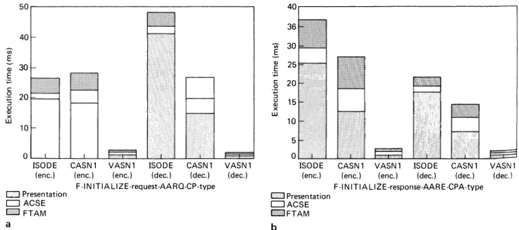
Measurements are divided into groups according to the regimes in which the corresponding PDUs are exchanged. The first group involves FTAM, ACSE and Presentation PD Us used during the FTAM association regime. During the connection establishment, F-INITIALIZE-request,AARQ and CP-type PD Us are sent from initiator to responder, which responds with F-INITIALIZE-response, AARE and CPA-type PDUs if it accepts the connection request. Values used for F-INITIALIZE-request and F-INITIALIZE-response are shown in Figure 15.
In Figure 16a,b, the total execution times for encoding/
decoding these PD Us are given in terms of individual encoding/decoding time figures for FTAM, ACSE and presentation PDUs. As can be seen, encoding/decoding of presentation PDUs takes much longer than for FTAM and ACSE PDUs, especially in the case of ISO DE, since they include conversion between the PE and the PS. We can also see that the performance of ISODE and CASNl (both measured on Sun 3/60 workstations) are comparable.
A-ASSRQ A-ASSCF A-ASS RP d A_ASSIN
IF-INITIALIZE-req) �IT""ni_ti_at--,or,...IF-INITIALIZE-req) IF-INITIALIZE-res) Respon er IF-INITIALIZE-req)
A-REL RO A_RELCF A_RELRP A-RELIN (F-TERM/NATE-req) (F-TERMINATE-res) (F-TERMINATE-res) (F-TERMINA TE-req)
,---"'---''--, ���� ACSE ACSE P_CQNRQ �IT""n _iti_at_or.---, P_CQNCF IA-AARQ) IA-AARE) P_RELRQ P-RELCF (A-RLRO) ,---"'---'--, (A-RLRO) Presentation S_CQNRQ Entity s_CQNCF ICP-type) �..---,... {CPA-type) S_R£LRQ
(ttdPPDU) (ttdPPDU) S_RELCF
P_CQNRP
IA-AARE) {A_AARQ) P_CQNIN
P_R£LRP P_REL!N /A-RLRE) �._____.� /A_RLRO) Presentation s_CQNRP Entity S_CQNIN {CPA-type) ���---' ICP-type) S_RELRE (ttdPPDU) Session Service S_RELIN (ttdPPDU)
Figure 14 Service primitives and exchanged PDUs during FTAM association
Performance of ASN.1 encoders/decoders: M Bilgic and B Sarikaya I I
I
I ftam-regime-pduI
f-initialize-requestI
l II
service-class
I
management-class. transfer-class. transfer-and-management-classf.
functional-unitsI
read. write. limited-file-management.enhanced-file-management. grouping[. attribute-groups i storage[.
fta m-qual ity-of-service no-recovery. contents-type-list j I.0.8571.5.3.
1.0.8571.5.1 . l.3.9999. l.5.9f. initiator-identity "bilgic".
filcstore-password jbinary "mypass l"f
ftam-regime-pdu
I
I
f-initialize-response
I
service-class
I
transfer-and-management-class f. functional-units jread. write. limited-file-management.enhanced-file-management. groupingf. attribute-groups jstoragef.
fta m-quality-of-service no-recovery. contents-type-list j I .0.8571.5.3.
1.0.8571.5.1. 1.3.9999.1.5.91 I
Figure 15 Examples of POU values
In the following benchmark tests (see Figures 17 and
18) we compare CASNl with VASNl. CASNl measure
ments were conducted on a Sun4 Spare 2 workstation, and VASNl performance figures were obtained from its VHDL model. These benchmark tests were
con-U) E Q) 30 E :;::; .2 20 Q)
!SODE CASN1 VASN1 !SODE CASN1 VASN1 (enc.) (enc.) (enc.) (dee.) (dee.) (dee.) D Presentation
D ACSE EZll FTAM a
F-IN ITIA LIZE-request-AARO-CP-type
ducted to measure the speed-up arising from concurrent POU processing and parallelism in VASNl.
The first group of measurements are conducted for the FT AM disconnection phase. To perform the dis connection, the initiator sends F-TERMINATE-request, RLRQ and ttdPPDU to the responder, which replies with F-TERMINATE-response, RLRE and ttdPPDU.
Figure 17 depicts the execution time for encoding/
decoding the F-TERMINATE-request, RLRQ and ttdPPDU. The results for reply PDUs are identical.
Figure 17a shows encoding times of 1, 2 and 4 POU
sets (F-TERMINATE-request, RLRQ and ttdPPDU),
and Figure 17b shows corresponding decoding times.
For CASNl , execution times for multiple POU sets are obtained from those of a single POU set by simple addition. Since VASNl modules can process multiple PDUs concurrently, the overall execution times for multiple POU sets show the exploitation of pipeline.
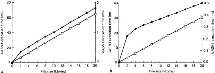
The other group of measurements are conducted in a data transfer regime. The ISODE FTAM service supports unstructured text, unstructured binary and filedirectory files. During the measurement of encoding/ decoding for bulk data transfer, the unstructured text file option is used. The FTAM initiator for bulk data transfer-write and the responder for bulk data transfer read separate the file into pieces, and then transfer them using the presentation service. Figures 18a.b show the performance ofCASNl and VASNl for the transfer of unstructured text files whose size ranges from 2000-20000 bytes for encoding and decoding, respectively.
For encoding 2000 bytes CASNl takes 6.91 ms, and VASNl 0.365 ms, a speed-up of 18.9. For encoding 20,000 bytes, while CASNl takes 64.52 ms, VASNl finishes the same work in 1.7 ms, increasing the speed up to 37.95. The performance ofVASNl is far superior to that of CASNl for decoding, since no data copying
40 36 -;;, 30 E a, 25 E ·.;::; C: 20 ·.;::; 15 a, UJ 10 5 0
!SODE CASN1 VASN1 !SODE CASN1 VASN1 (enc.) (enc.) (enc.) (dee.) (dee.) (dee.)
F-1 N ITIA LIZE-response-AAR E-CPA-type c:J Presentation
DACSE EZllFTAM
b
Figure 16 Encoding/decoding time for connection establishment PDUs. (a) Encoding: (b) decoding
Performance of ASN.1 encoders/decoders: M Bilgic and B Sarikaya 3.5 3 2.5 Q) E ·.;:::; 2 C ·.;:::; 1.5 :, Q) UJ 0.5 0 0VASN1 a ff)] CASN1
Number of sets of PDUs
2.5 2 .;;-E Q) 1.5 E ·;:; C 0 ·.;:::; Q) X UJ 0.5 1 0VASN1 b 1EllilcAsN·1 2 4 Number of sets of PD Us Figure 17 Encoding/decoding time for connection release PDUs. (a) Encoding: (h) decoding
80 2 40 0.5 .;;-E 60 Q) E ·.;:::; 0 ·;:; :, 40 Q) V, E E .;;- .;;-0.4 E Q) Q) 30 Q) E E E ·.;:::; ·.;:::; ·.;:::; C C 0.3 C 0 0 0 ·.;:::; :, ·.;:::; :, 20 ·;:; :, u u u Q) X Q) X Q) 0.2 X Q) Q) Q) z 20 <( z z z en en 10 (/) <( > <( u 0.1 <( > 0 0.0 2 4 6 8 10 12 14 16 18 0 2 4 6 8 10 12 14 16 18 20
a File size (kbytes) b File size (kbytes)
Figure 18 CASNI and VASNI encoding/decoding times for hulk data transfer. (a) Encoding: (h) decoding. e: YASNI: D: CASNI
takes place during either the parsing or the decoding itself. As can be seen from Figure 18, VASNl finishes decoding 2000 bytes in 0.224 ms and CASNl takes 3.26 ms, therefore VASNl is 14.55 times faster than CASN I. V ASN 1 decodes 20,000 bytes in 0.5005 ms and CASNl decodes in 30.47 ms, a speed-up of 60.88. This dramatic increase in speed-up for decoding is a result of two factors: VASNl performs no data copying, and its pipe is fully utilized.
CONCLUSION
In this paper, the OSI data representation standard ASN. l, along with the standard encoding rules set BER, are discussed. Two different software systems used to generate A�N. l encoder/decoder routines, as well as a multiprocessor architecture for ASN.l encoding/decoding, are discussed. We have presented the performance results for three different ASN.1 encoder/decoders on PDUs transferred during the service of FTAM ASE of an ISODE package. The following conclusions can be drawn:
• The performance of VASNI is always superior to that of the software-based approaches. VASNl becomes especially attractive when PDUs from FTAM, ACSE and presentation are embedded and a number of FTAM PDUs are sent as a group. • The data copying amounts to a large portion of
encoding/decoding of bulk data PD Us. The advantage ofusing pointers instead of copying the data itself in VASNl becomes more apparent in the decoding. • Due to its connection-oriented nature, FTAM
necessitates a considerable number of PD Us besides the bulk data PD Us. Particularly when only a single file transfer is done for each association, the total encoding/decoding time of these PDUs becomes much larger than that of bulk data PDUs.
Although ASN.1 encoding/decoding contributes to a fair portion of the total execution time, the performance of other functional blocks of the protocol is also the major factor in determining the protocors performance. It should also he noted that the implementation strategy is another important factor. The use of an encoder/decoder parallel to the host machine, which
Performance of ASN.1 encoders/decoders: M Bilgic and B Sarikaya
includes the other protocol functionalities, is another dimension of concurrency, and in turn may be another source of further performance improvement providing an efficient interface.
Future study will include investigation of the effects of the ASN.1 encoding/decoding on overall protocol performance. This is especially interesting when parallel bulk transfers or parallel associations take place between two FTAM ASEs which will provide VASNl to use its pipeline and to exploit the encoder/ decoder, host parallelism.
The benchmarks reported in this paper were con ducted for the file transfer application. It will be interesting to conduct similar benchmark tests for other OSI applications like e-mail, directory services, etc.
REFERENCES
Strayer, WT and Weaver, A C "Performance measurement of data transfer services in MAP". IEEE Network. Vol 2 No 3 (May 1988) pp 75-81
2 Chesson, G 'XTP/PE overview·. Proc. 13th Co1if' 011 Local
Computer Networks. Minneapolis. MN (October 1988) pp 292-296
3 Clark, D D et al. 'An analysis of TCP processing overhead'.
IEEE Commun .. Vol 27 No 6 (June 1989) pp 23-29
4 Gunningberg, Pet al. 'Application protocols and performance benchmarks'. IEEE Commun.. Vol 27 No 6 (June 1989) pp 30-36
5 CCITT Recommendation X.208. Specification o/Ahsrracr Svmax
Norarion One (ASN.I). Geneva. Switzerland (1987)
6 CCITT Recommendation X.209. Specification a/Basic Encodin?,
Rules for Ahsrracr Symax Notation One (ASN.f). Geneva. Switzerland (1987)
7 Neufeld, G W and Yang, Y The design and implementation of an ASN.1-C compiler'./£££ Trans. Softw. Eng .. Vol 16 No IO (October 1990) pp 1209-1220
8 ISODE. The ISO Developmrnt E11vironn1<.'11T: U1-er Manual. Wollongong Group. Palo Alto. CA
9 Brady, F, Boshier, AG, Pitt, D and Szcygiel, BM ·one20ne - A tool for translating ASN.l to ACT ONE'. Proc. FORTE'90. Madrid. Spain (November 1990)
IO Bilgic, M Concurrenr Protocol Dara Unir Encoding/Decoding:
Algorithms. Architecrures and Perfonnance Evaluarion. PhD thesis. Concordia University. Canada (June 1992)
11 Nakakawaji, T, Katsuyama, K, Miyaushi, N and Mi:imno, T 'Development and evaluation of APRICOT (Tools for Abstract Syntax Notation One)'. Proc. 2nd Im. Symposium on Inreroperahle
Information Sysrems. Tokyo. Japan (1988)
12 Wu, W, Bilgic, M and Sarikaya, B 'VHDL modelling and synthesis of an ASNI encoder/decoder·. CCVLSI 90. Ottawa. Ontario (October 1990) pp 1.5.1-1.5.8