CONCEPTUAL DESIGN OF AN X-FEL FACILITY USING CLIC X-BAND
ACCELERATING STRUCTURE
A. Aksoy
∗, Ö. Yavaş, Institute of Accelerator Technologies, Ankara, Turkey
D. Schulte, A. Latina, W. Wuensch, I. Syratchev, A. Grudiev, S. Stapnes CERN, Geneva, Switzerland
Z. Nergiz, Nigde University Physics Department, Nigde, Turkey
M. Doğan, Dogus University, Istanbul, Turkey
G. D’Auria, S. Di Mitri, C. Serpico, Elettra, Trieste, Italy
M. Boland, J. McKinlay, Synchrotron Light Source Australia, Clayton, Australia
J. Clarke, D. Angal-Kalinin, STFC, Daresbury Laboratory Cockcroft Institute, Daresbury, UK
R. Ruber, T. Ekelof, V. Ziemann, Uppsala University, Uppsala, Sweden
Q. GU, W. Fang, Shangai Institute of Applied Physics, Shanghai, China
E. Gazis, A. Charitonidis, National Technical University of Athens, Greece
Abstract
Within last decade a linear accelerating structure with an average loaded gradient of 100 MV/m at 12 GHz has been demonstrated in the CLIC study. Recently, it has been pro-posed to use the CLIC structure to drive an FEL linac. In contrast to CLIC the linac would be powered by klystrons not by a drive beam. The main advantage of this proposal is achieving the required energies in a very short distance, thus the facility would be rather compact. In this study, we present the conceptual design parameters of a facility which could generate laser photon pulses covering the range of 1-75 Angstrom. Shorter wavelengths could also be reached with slightly increasing the energy.
INTRODUCTION
X-band accelerator development has gained improve-ment within last ten years, motivated by the need for gradient accelerators for the future linear colliders in high-energy physics research [1]. Design of accelerator cells [2], manufacturing [3], and characterization technique [4] have been developed. Due to limited RF power source avail-ability for X-band frequencies, the accelerating principle at X-band frequencies were based on two beam accelerating (TBA) scheme. Simply the TBA scheme can be described as following; The RF power is generated by a high current electron beam (drive beam) running parallel to the x-band accelerator. This drive beam is decelerated in special power extraction structures and the generated RF power is trans-ferred to the x-band accelerator. In other words the drive beam power extraction structures acts as any active RF com-ponents (i.e. klystrons) as it is at Compact Linear Collider (CLIC) project [5]. The development of power sources for x-band structures [6] gives opportunity this technology to be used as traditional accelerators especially in FEL designs.
MACHINE DESCRIPTION
The proposed facility is a 6 GeV linac, consisting of an S-Band injector and high-gradient X-band main
accelera-∗[email protected]
tor which can deliver a high-repetition rate low-emittance beam, one or several undulator sections and photon beam lines with a user facility. The proposed layout is given with Fig. 1. Expected facility length is about 550 m and basic parameters of facility is given in Table 1.
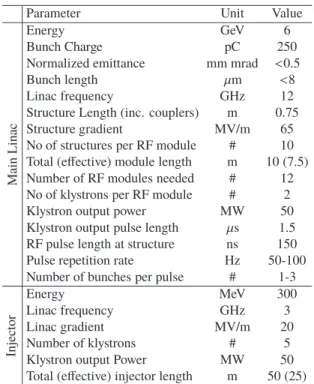
Table 1: Basic Parameters of an X-FEL Facility Based on X-Band linac
Parameter Unit Value
Mai n L inac Energy GeV 6 Bunch Charge pC 250
Normalized emittance mm mrad <0.5
Bunch length μm <8
Linac frequency GHz 12
Structure Length (inc. couplers) m 0.75 Structure gradient MV/m 65 No of structures per RF module # 10 Total (effective) module length m 10 (7.5) Number of RF modules needed # 12 No of klystrons per RF module # 2 Klystron output power MW 50 Klystron output pulse length μs 1.5 RF pulse length at structure ns 150 Pulse repetition rate Hz 50-100 Number of bunches per pulse # 1-3
In jecto r Energy MeV 300 Linac frequency GHz 3 Linac gradient MV/m 20 Number of klystrons # 5 Klystron output Power MW 50 Total (effective) injector length m 50 (25)
Injector
The injector is proposed to be similar to the injector at SwissFEL [7] . It is based on S-band RF gun operating at about 100 MV/m gradient and standard S-band structures operating at about 20 MV/ gradient. However if the beam pulse repetition rate is required to increase up to 500 Hz one should also design the S-band structures of injector for such repetition.
THPRO025 Proceedings of IPAC2014, Dresden, Germany
ISBN 978-3-95450-132-8 2914 Copyright © 2014 CC-BY -3.0 and by the respecti v e authors
02 Synchrotron Light Sources and FELs A06 Free Electron Lasers
Figure 1: Layout of proposed facility.
Main Accelerator
X-band accelerating structures developed for CLIC project [8] are planned to be used in main accelerating sec-tion. In order to define structure parameters such as gradi-ent, structure length, aperture etc., we initially have checked the effect of single bunch wake field along the main linac. If the beam is injected with an offset, e.g. from beam jitter, the transverse wake fields in the linac will induce an
addi-tional oscillation of the centroid of the bunch, which is 90◦
out of phase with the initial oscillation [9]. We require that
the ratio AA
0 of this induced oscillation to the original (in
normalised coordinates) remains small AA
0 << 1.
Figure 2 shows the curves of maximum amplifications of
max[Ax
Ax0] = 0.1 and 0.4 versus gradient of two different
CLIC structure (CLIC-502 [8], CLIC-G [10]). As it can
be seen on the figure in order to get max[Ax
Ax0] = 0.4 the
gradient of CLIC-G structure must be more than 110 MV/m while the gradient above 35 MV/m is acceptable for CLIC-502 type of structure. Both structure do not allow to get
max[Ax
Ax0]= 0.1 amplification.
Figure 2: Amplification curves of a single bunch versus
gra-dient anda/λ of structures. a/λ line above curves is
accept-able.
Cost estimation has been done using the structure database of CLIC taking into account wake field effect, gra-dient, length, input power of structures, also considered cost of module consisting the pulse compressor. The summary of cost estimation is given with Table 2.
Pulse compressor and RF module layout: Using the results given in Table 2, 10 structures will be installed on one RF module and fed by one RF station which is essen-tially is combination two klystrons. Schematic view of the module and power combination/distribution system is given with Fig. 3.
Two klystron that each has power of 50 MW and pulse
length of 1.5μs will be driven by two individual modulator.
The RF pulses will be combined with hybrids combiners. Single RF pulse that has 100 MW power and 1.5μs length
Table 2: Summary of Basic Parameters of Cost Optimiza-tion
Parameter CLIC-502 Optimum Structures per RF unit 12 16 10 Klystrons per RF unit 2 2 2 Structure length (m) 0.23 0.23 0.75
a/λ 0.145 0.145 0.125
Operating gradient (MV/m) 77 67.5 65 Energy gain per RF unit (MeV) 213 248 488
RF units needed 27 23 12
Total klystrons 54 46 24
Linac active length (m) 74 84 88 Cost estimate (a.u.) 76.2 71.5 51.7
Figure 3: Schematic view of proposed RF unit (module).
will be compressed to 150 ns by SLED-II delay lines [11]. After compression expected RF power is 468 MW. The com-pressed power will be distributed by an RF network to each structure evenly which means each structure will be fed by 46.8 MW power yielding 68.8 MV/m gradient.
SIMULATIONS
Preliminary simulations has been performed for the in-jector, main accelerating section and FEL generation.
Injector: Similar to LCLS [12] a 1.5 cell photo cath-ode RF gun operating 100 MV/m gradient at 3 GHz is pro-posed for the electron source. The cathode of the gun is assumed to deliver 250 pC bunch charge and 9 ps full width half maximum bunch length. Travelling wave accelerating structures that are operating with 20 MV/m gradient at 3 GHz are fallowed the RF gun similar to SwissFEL. Astra code [13] has been used for simulations and optimization injector section. The beam size and emittance along the in-jector is given with Fig. 4. As it can be seen the projected
normalized emittanceεxis below 0.5 mm.mrad.
Proceedings of IPAC2014, Dresden, Germany THPRO025
02 Synchrotron Light Sources and FELs A06 Free Electron Lasers
ISBN 978-3-95450-132-8 2915 Copyright © 2014 CC-BY -3.0 and by the respecti v e authors
Figure 4: Horizontal emittance and beam size through the injector.
Figure 5: Beam energy, and Twiss functions along the linac.
Main accelerating section: The injector is followed by an X-Band structure as a chirp linearizer in order to perform better bunch compression. A bunch compressor is located after the linearizer structure afterward two stage main ac-celerating section separated with bunch compressor is pro-posed for the main accelerating section (see Fig.1). FODO type of lattice is proposed for beam transport and Elegant code [14] has been used for tracking.
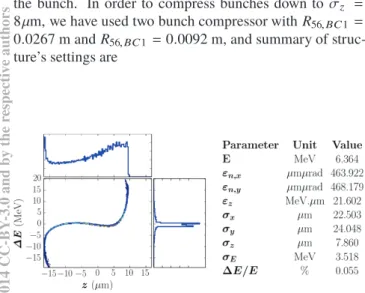
Figures 5 and 6 show the beam energy and Twiss func-tions along the linac and final longitudinal phase space of
the bunch. In order to compress bunches down to σz =
8μm, we have used two bunch compressor with R56,BC1 =
0.0267 m and R56,BC1= 0.0092 m, and summary of
struc-ture’s settings are
Figure 6: Longitudinal phase space and beam parameters of bunch at the end of linac.
Name of section No. of struc. G (MV/m) φRF(deg)
Gun S-band 1 100 26
Injector S-band 4 16 20
Injector X-band 1 62.2 151.5
Linac1 X-band 40 65 20
Linac2 X-band 90 65 -15
After such compression RMS peak current isI ≈ 9 kA and
RMS energy spread isσE/E ≈ 0.06%.
Lasing Section: We have also performed simulations for the lasing section using GENESIS [15] code. We have used planar type of undulators located on FODO type of lattice. We assumed each undulator have about 4.2 m length, 15 mm period length and 1 undulator strength. Using the longitudinal bunch distribution given with Fig. 6 we have found that the power of laser at 0.9 Å resonant wavelength saturates at around 75 m and power reaches to several GWs which is typical number for X-FELs.
CONCLUSION
Applications of X-band technology in linacs is rapidly ex-panding due to its great potential already shown and the pos-sibility to operate it at gradients up to 100 MV/m. This will also benefit the interest for very compact high energy linacs for hard X-ray FELs. A committee consist of several insti-tutions which are interested X-FEL has been studying on usage of CLIC X-Band structure for driving an FEL facility in order to write a common conceptual design report (CDR) for such an X-FEL facility. It is planned that the CDR will be completed by the end of 2014 and several projects are going to be started in next years.
In this paper we focused on feasibility of usage of CLIC X-Band structures driving an FEL facility. We described preliminary simulations. It is shown that the bunches can be
compressed down toσz= 8μm and the radiation below 1 Å
can be produced in SASE mode. However energy options of 3 GeV and 12 GeV will be studied as well as the tolerance requirements of such machine. High repetition rate up to 500 Hz, seeding FEL generation and tapered type undulator options will also be studied in future.
REFERENCES
[1] J. W. Wang et al., "Accelerator Structures R&D for Linear Colliders", PAC99, New York, USA (1999).
[2] J.W. Wang et al., "Fabrication Technologies of the high gra-dient accelerator structures at 100 MV/m range", IPAC 2010, Kyoto, Japan.
[3] A. Grudiev, W. Wuensch, "Design of the CLIC main linac accelerating structure for CLIC Conceptual Design Report", LINAC 10, Tsukuba, Japan, (2010).
[4] A. Degiovanni et. al., "High-Gradient Test Results From a CLIC Prototype Accelerating Structure: TD26CC", IPAC’14, Dresden, June 2014, these proceedings.
[5] M. Aicheler, et.al. , "A Multi-TeV linear collider based on CLIC technology: CLIC conceptual design report", CERN, Geneva (2012).
THPRO025 Proceedings of IPAC2014, Dresden, Germany
ISBN 978-3-95450-132-8 2916 Copyright © 2014 CC-BY -3.0 and by the respecti v e authors
02 Synchrotron Light Sources and FELs A06 Free Electron Lasers
[6] J. Kovermann et al., "Commissioning of the first klystron-based x-band power Source at CERN", IPAC2012, New Or-leans, Louisiana, USA (2012).
[7] R. Ganter, “SwissFEL Conceptual Design Report” ,PSI Bericht 10-04 (2012).
[8] A. Grudiev and D. Schulte, “The Accelerating Structure for A 500 GeV CLIC”, LINACâĂŹ10, Tsukuba, September 2010. [9] A. Aksoy, et al., “Beam dynamics simulation for the Compact
Linear Collider drive-beam accelerator”, Phys. Rev. ST Accel. Beams, v:14, i:8, p:84402, (2011).
[10] J. Shi, et al. “Tuning of CLIC Accelerating Structure Proto-types at CERN”, LINAC2010, Tsukuba, Japan, (2010). [11] C. Nantista, et al., “High-Power RF Pulse Compression with
SLED-II at SLAC”, SLAC-PUB 6145 (1993) EPAC’96 [12] C.Limborg, et al., “RF Design of the LCLS Gun”,
LCLS-TN-05-3, 2006.
[13] K. Floettmann, “ASTRA User Manual”, (2011). [14] M. Borland, “User’s Manual for Elegant”, 2013 [15] S. ReicheM. Borland, “Genesis User’s Manual”, 2004.
.
.Proceedings of IPAC2014, Dresden, Germany THPRO025
02 Synchrotron Light Sources and FELs A06 Free Electron Lasers
ISBN 978-3-95450-132-8 2917 Copyright © 2014 CC-BY -3.0 and by the respecti v e authors