1Abstract—In power electronic applications, especially high power and medium voltage, multilevel inverters (MLIs) have been commonly used. MLIs ensure high quality load voltage and lower Total Harmonic Distortion (THD) than traditional inverter. In this paper, a multilevel inverter structure with reduced number of power switches is proposed. The proposed multilevel inverter is lower costed than conventional MLI. Also, a Genetic Algorithm (GA) based Selective Harmonic Elimination (SHE) technique has been used for the first time in the proposed MLI structure with reduced number of switches. The proposed GA based SHE technique computes the optimum switching angles by solving nonlinear harmonic equations of multilevel inverter. Both Isochronous switching (IS) and SHE techniques have been applied to proposed MLI to demonstrate the effectiveness of the GA based SHE technique. Simulation and experimental results for 7, 11 and 13-level have been obtained. Results of 11-level inverter is analysed and given in detail. Results have clearly proved that desired order harmonics in proposed MLI topology can be eliminated by using GA based SHE technique and lower THD on the load voltage has been provided.
Index Terms—Genetic algorithm; Multilevel inverter; Reduced number of switches; Selective harmonic elimination; Total harmonic distortion.
I. INTRODUCTION
Multilevel inverter has been an alternative DC/AC power conversion device instead of traditional two-level inverter in high power and medium voltage applications. The voltage stress on semiconductor switches increases with rising desired power and voltage. Since, semiconductor power switches qualified enough to withstand medium voltage levels can’t be produced with available technology, usage of MLI has become more popular in medium voltage [1], [2].
The first type of multilevel inverters was cascaded H-bridge multilevel inverter and presented in 1975. Then, diode clamped multilevel inverter (DCMLI) and capacitor clamped multilevel inverter (CCMLI) topology were developed, respectively [3], [4]. DCMLI structure has
Manuscript received 14 December, 2018; accepted 4 February, 2019. This research was funded by the Scientific Research Project Coordinating Office of Selçuk University (SUBAP).
unbalanced voltage problem so CCMLI structure was developed in order to eliminate the unbalanced voltage problem. Unfortunately, these structures need extra clamped diodes and clamped capacitors the number of which rise exponentially with rising level. Using of extra diodes and capacitors make the structure of multilevel inverter complicated and the system cost increases. But, cascaded H-bridge topology doesn’t require clamped capacitor or diodes and have the series connection of H-bridge modules with same structure. Therefore, the cascaded H-bridge topology becomes more attractive especially in high voltage level applications [1], [5], [6].
There have been several switching strategies can be applied to MLI structures. One of these is Isochronous Switching (IS) getting switching angles analytically to obtain equal voltage step. However, this technique doesn’t allow controlling of the desired harmonic order, total harmonic distortion (THD) and modulation index. Another technique is Selective Harmonic Elimination (SHE). SHE is one of the outstanding techniques that provides to control modulation index and to eliminate desired harmonic order. SHE technique produces the switching angles in order not to generate some harmonics especially low order harmonics by solving nonlinear equations derived from Fourier expansion of load voltage [6]–[9]. These equations vary according to number of harmonics desired to eliminate. SHE technique offers to control amplitude of output voltage by solving the equation simultaneously [10]. That is, SHE technique requires different solution that changes based on each modulation index and harmonics’ order desired to eliminate. The usual methods such as Symmetric Polynomials and Groebner Bases Theory solve SHE equations analytically or iteratively [11], [12]. But, these methods are inconvenient to implement because these methods require initial value and divergence problem are probably to come into existence [1], [14]. SHE equations can be adapted to artificial intelligence approaches and many studies conducted in [10], [13]–[15] have used different optimization algorithm. Particle Swarm Optimization (PSO) and Genetic Algorithm (GA) have been used and compared with each other in [13]. Another approach in [14] has used Colonial Competitive Algorithm
GA Based Selective Harmonic Elimination for
Multilevel Inverter with Reduced Number of
Switches: An Experimental Study
Enes Bektas
1, Hulusi Karaca
2 1Department of Electrical and Electronics Engineering, Engineering Faculty, Cankiri Karatekin
University,
Cankiri, Turkey
2
Department of Electrical and Electronics Engineering, Technology Faculty, Selcuk University,
Konya, Turkey
to solve harmonic equations and to minimize low order harmonics. In [15], adaptation of SHE equations to Neural Network has been studied.
Multilevel inverters have important advantage such as low distortion in input current, working at low switching frequency, good electromagnetic compatibility, lower voltage stress on power switches and lower switching loses when compared to traditional two level inverter [1], [2], [16]. The most important characteristic of MLI is that load voltage waveform resembles the sinusoidal form and THD in the output decreases by rising level. However, necessity of power device in the hardware increases, unfortunately, system cost increases. To overcome this problem, many researches have been done about the structure of multilevel inverter with reduced number of switches [17]–[28]. But, these studies have focused on only reducing of power switches’ number in MLI hardware. Besides reducing of switches’ number in MLI structure, it is also important that the load voltage must be qualified by eliminating some low order harmonics. In addition, using of low pass filters is obligation to generate pure sinusoidal voltage with non-harmonic contents. So, capacitor rate in the power filter needed in output side and system cost can be reduced.
In this work, multilevel inverter with reduced number of switches has been proposed and realized experimentally. Both Isochronous Switching technique and Selective Harmonic Elimination technique have been applied to the proposed multilevel inverter. The outstanding difference of this work from the studies in [17]–[28] is that this paper can eliminate desired order harmonics in load voltage of multilevel inverter structure with reduced number of switches. In order to eliminate the desired order harmonics, GA based SHE technique has been applied. SHE technique is based on calculation of switching angles accurately. For this reason, switching angles with optimal solution have been obtained by GA software without utilizing of GA&Optimization Toolbox. Thus, THD values of each level are decreased in the load voltage. The compact output filter is enough, thanks to improved THD values. Experimental and simulation results of IS and SHE techniques have been compared with each other. It can be proved from the results that GA based SHE technique can be applied to proposed MLI topology effectively.
II. PROPOSED MULTILEVEL INVERTER WITH REDUCED NUMBER OF SWITCHES
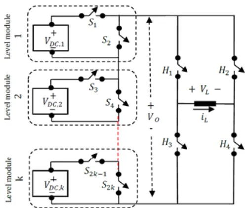
The proposed multilevel inverter structure is given in Fig. 1 and includes cascaded Half-bridge modules and H-bridge inverter at the load side. H-H-bridge inverter is used as polarity changer. Each level module has isolated DC sources. The number of DC sources changes based on desired load voltage level. Each level module has same structure as shown in Fig. 1.
In order to get high level and high voltage, number of level modules can be easily increased by connecting level module in series. In Fig. 2, the symmetric stepped output voltage of cascaded level modules and the load voltage have been given. As known symmetric multilevel inverters need equal DC source however asymmetric multilevel inverter has unequal DC source.
Fig. 1. Proposed multilevel inverter structure.
The symmetric stepped output voltage of cascaded level modules and load voltage can be formulated as:
, o V kVDC (1) , L V kVDC (2)
where k is the number of level modules and Vo is the output voltage of cascaded modules applied to H-bridge inverter. k also represents the number of isolated DC sources and VL is the AC load voltage. The level number of load voltage can be calculated for symmetric multilevel inverter as in (3). And switches’ number is formulized by (4):
2 1,
Nlevel k (3)
3 2 4.
NswitchesNlevel k (4)
Fig. 2. Load voltage and output voltage of cascaded modules.
Cascaded H-bridge and proposed multilevel inverter’s structure doesn’t require extra clamped capacitor and diodes as in DCMLI and CCMLI. And so, proposed and H-bridge topology make the inverter size is smaller [5], [6] as compared with others. While structure of cascaded H-bridge multilevel inverter needs 4k switches to get stepped output voltage, the number of switches is 2k + 4 in proposed multilevel inverter [1], [2].
III. ISOCHRONOUS SWITCHING TECHNIQUE
There have been several switching techniques can be applied to multilevel inverter. Based on the generalized stepped-voltage illustrated in Fig. 2, switching angles can be derived by using (5). This switching technique is called as Isochronous Switching, since each switching time is divided equally
/ (2 1),
n k
n
(5)
where αn are switching angles as radian. Isochronous switching can generate load voltage at demanded frequency. In order to get 50 Hz output voltage, 0.01 second corresponds half wave period.
IV. GABASED SELECTIVE HARMONIC ELIMINATION Nonlinear harmonic equations required to obtain optimal switching angles can be stated by Fourier expansion of load voltage. GA based SHE technique aims to calculate switching angles which provide desired modulation index and elimination of desired low order harmonics. The load voltage that includes all harmonic components has been defined as in (6) [1], [2] 1 2 ( ) 1,3,.. 4 ( ) [cos( ) cos( ) ... cos( )]sin( ). DC L odd n k kV V t n n n n t (6)
The harmonic components of load voltage occur at fundamental frequency and are multiples of fundamental frequency. Even-harmonic components have not existed because of the symmetrical load voltage shown in Fig. 2. Therefore, (6) can be used for calculation of odd-harmonics components. The first odd harmonic component is the fundamental waveform, V1
1 1 2
1
4
( ) [cos( ) cos( ) ... cos( ) cos( )]sin( ).
DC k k kV V t t
(7)SHE technique enables to control modulation index of fundamental waveform. And, modulation index is defined as following
. 1 ( DC)
M V kV (8)
Nonlinear SHE equations derived to eliminate desired harmonic orders and to control modulation index can be defined as given in (9). The generalized mathematical statement of SHE equations consists of k harmonic equations for (2k + 1)-level inverter. First of these harmonic equations is defined to adjust the amplitude of fundamental waveform. Therefore, it is possible to eliminate k-1 harmonic component with SHE technique [1], [7]. The nonlinear SHE equations can be adapted to elimination of some harmonic orders. So as to solve nonlinear SHE equations and compute switching angles, there have been conventional methods such as Newthon-Raphson, Symmetric Polynomials and Groebner Bases Theory. These methods calculate the switching angles iteratively and analytically. However, these methods may not give the optimum switching angles. Only one specific solution can be got by conventional methods. Also, these methods require initial values and may cause to the divergence problems
1 2 1
1 2 1
cos( ) cos( ) ... cos( ) cos( ) ,
4 cos(3 ) cos(3 ) ... cos(3 ) cos(3 ) 0,
k k k k Mk 1 1 cos((2 3) ) ... cos((2 3) ) 0, cos((2 1) ) ... cos((2 1) ) 0. k k k k k k (9)
Fortunately, artificial intelligence approaches have multiple solutions for any optimization problem. In addition, nonlinear SHE equations can be defined as an optimization problem. GA solving optimization problems is a type of artificial intelligence approach and can be adapted to elimination of desired harmonic orders. For this reason, GA is more feasible than conventional methods. In this paper, nonlinear SHE equations of 7, 11, 13-level load voltage have been solved by using GA. GA defines constraints function and uses optimization operators such as, fitness function, mutation etc. Solving of optimization problems and adapting of GA to nonlinear SHE equations have been presented in Section IV-A.
A. Genetic Algorithm
Genetic Algorithm is an artificial intelligence approach that can be used to solve any optimization problem. By using any artificial approach or analytical method it is not possible to make harmonics equal to zero. However, all calculation methods make the value of harmonic components near-zero. Therefore, in order to calculate switching angles eliminating desired order harmonics by means of GA, eliminated harmonic components must be defined as constraints. In addition, nonlinear SHE equations resemble nonlinear constrained optimization problems having objective function and constraint function [1], [2]. The general formulation of constraint optimization problems is given in following 1 1 2 3 2 1 1 2 , ( ), , ,..., , 0, , , 0 ... / 2, g g g Minimize y F x h h h h Constraints x x x (10)
where h is the harmonic component desired to eliminate, g is the number of DC sources or switching angles and x with consecutive indexes are the switching angles of nonlinear SHE equations [29], [30].
GA starts with generation of chromosomes that constitute starting population. Chromosomes including the genes are defined for each switching angle. The genes can be generated by using real coded, binary or grey coded. In this paper, the real coded GA has been used. In addition, genes are produced randomly according to limits of switching angles between 0 and π/2 given in equation set (10). Chromosomes look like in GA software calculating switching angles of SHE equations
1 _ (0.03, 0.255,...,1.411), (0.147, 0.295,...,1.376). pop size Chromosome Chromosome (11)
The size of population varies with the type of optimization problems and must be selected carefully. If the starting population size is excessive, the Algorithm works slowly. In addition, with low population size, deviation may
occur.
After generating of starting population, selection occurs. Selection is the process determining which chromosome is more feasible for the Algorithm. There have been many types of selecting operator such as pairing based on cost, roulette wheel and tournament. In tournament selection, the pairs of chromosomes are chosen randomly. Penalty function determines whether chromosomes would be produced over again as to range of constraint functions. This range is defined between 0 and 0.01 in this study. Penalty function is given as , 1 2 ( ) 1 ( ) ( ) k [ ( ) ]z odd z P x F x r h x (12)
where P(x) is the penalty function, F(x) is the fitness function, r is 500, g is the number of switching angles, h(x) is the constraints in that harmonics desired to eliminate. In penalty function, r is the specific parameter changing according to type of optimization problem and can be specified by comparing the performance of the GA with different value of r.
Tournament selection has three sections:
If constraint function of pairs is not in desired range, chromosome having less penalty function is selected for new population,
If penalty function of one chromosome in the pairs is equal to zero and another is not, this chromosome is selected in for population,
If constraint function of pairs is in desired range, chromosome having less penalty function is selected for new population [1], [2].
With three sections of tournament function, starting population is generated again. Therefore, chromosomes which are more feasible for harmonic elimination have been chosen for the algorithm.
After the selection, crossover operator works. There have been several crossover operators such as flat, uniform and discrete crossover [31]. In this paper, arithmetical crossover technique has been used. Arithmetical crossover technique chooses the pairs of chromosomes randomly. In addition, the random vector A is generated between 0 and 1 for mutual genes of all chromosome pairs. If A is smaller than crossover rate, mutual genes are included crossover process as to (13) and new genes are created for new chromosomes:
_1 _1 _ 2
_ 2 _ 2 _1
(1 ) ,
(1 ) ,
pair pair pair
pair pair pair
NewGene p Gene pGene
NewGene p Gene pGene
(13)
where p is the parameter of crossover equation and has been defined as 0.2. To increase variety of chromosomes, crossover rate has been chosen approximate to 1.
After crossover, mutation occurs. There have been many types of mutation operator such as bit flip, boundary, non-uniform and creep. In this paper, the non-uniform mutation has been used and mutation rate (M) is defined as 0.1. Uniform mutation starts with generation of random mutation vector (R) whose elements, corresponding to genes, are between 0 and 1 for each chromosome. Gene is reproduced randomly
within constraints of genes if the element of R is less than M. These constraints are different for each gene as seen in (10).
After mutation, the GA calculates the fitness value according to fitness function (FF). Evaluation of fitness value for each chromosome is the most important point. Because the best chromosome is specified by considering this and stored in order to compare with best chromosome in the next iteration. For this reason, the FF must be defined carefully so as to choose best chromosome making the sum of harmonics minimum [1], [2]. The FF used in this paper has been given in following
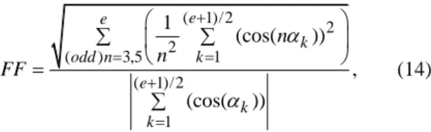
( 1)/2 2 2 ( ) 3,5 1 ( 1)/2 1 1 (cos( )) , (cos( )) e e k odd n k e k k n n FF (14)
where “e” is the maximum order of harmonics desired to eliminate. Also “e” can be stated as 2k – 1. Finally, GA calculates fitness values of each chromosome at the end of each iteration and choses the best chromosome by comparing next iteration. In the last iteration, the best chromosomes are chosen and switching angles are obtained as radians.
B. Calculation of Switching Angles and Modulation Indexes for SHE
SHE technique used in this paper has aimed to achieve the same modulation indexes in IS. Finally, switching angles for load voltage at desired modulation index have been calculated by GA software. Calculated switching angles for all level between 5 and 13 can be seen in Fig. 3. In 5-level inverter, 3rd harmonic order has been eliminated. In 13-level
inverter, 3rd, 5th, 7th, 9th and 11th harmonic orders have been
eliminated.
Fig. 3. The switching angles calculated by GA based SHE technique. In Table I, the modulation indexes calculated in all level between 5 and 13 by using (7) and (8) have been given for Isochronous Switching and SHE. In addition, Table I includes modulation indexes obtained by GA based SHE technique. It is apparent that the modulation indexes of IS technique have been accomplished by GA based SHE technique with little deviation.
TABLEI.MODULATIONINDEXESINISOCHRONOUSSWITCHING TECHNIQUE. Level 5 7 9 11 13 Modulation-IS 0.87 0.855 0.85 0.8395 0.835 Modulation-SHE 0.87 0.85 0.86 0.839 0.83 V. RESULTS
In this paper, Isochronous Switching technique and GA based selective harmonic elimination technique have been applied to 7, 11 and 13-level inverter experimentally. Results of 11-level inverter have been given in detail. The DC voltage of each level module is 12 V. Simulations have been developed in MATLAB/Simulink.
Simulation and experimental results have been compared with each other to demonstrate that desired harmonic orders can be eliminated by achieving aimed modulation indexes. Experimental results are coherent with simulation results. The nonlinear SHE equations have been solved by GA software coded in MATLAB.
In this paper, three types of THD have been calculated. First is the general total harmonic distortion called as THD. Harmonic components until 20th have been taken into
consideration. Second is the THDe that represents the sum of
harmonics until the maximum harmonic order that is eliminated. Third is WTHD, Weight Total Harmonic Distortion. THD, THDe and WTHD can be calculated as in
(15), (16) and (17) respectively. For THD and WTHD the upper limit is infinite. However, THDe is calculated until
eliminated harmonics: 2 2 2 3 5 7 1 ... , V V V THD V (15) 2 2 2 3 5 2 1 1 ... , k e V V V THD V (16) 2 2 2 2 2 2 3 3 5 5 7 7 1 ... , V V V WTHD V (17)
where k is the number of level modules or the number of DC sources. “e” is the maximum order of harmonics desired to eliminate. Also “e” can be stated as 2k-1. The objective of the study is to eliminate the desired consecutive odd order harmonic components. Thus, THDe is derived from the THD
and the Fitness Function is associated with THDe directly. A. Simulation Results
In Fig. 4, 11-level inverter load voltages have been given for IS and SHE. It is apparent that load voltage’s maximum rate is 60 V because of five level modules in 11-level inverter. However, switching angles are different from each other.
THD, THDe and WTHD values of SHE technique are
lower than IS technique. THDe values calculated until
maximum harmonic order desired to eliminate are 20.74 %, 17.66 % and 16.96 % in IS technique. Fortunately, these values are 0.25 %, 0.56 % and 2.03 % in 7, 11, 13-level inverter respectively in SHE technique. And similar reduction has been observed in WTHD values. While output level rises from 7 to 13, the THD value decreases to 8.22 %
from 17.58 % for SHE technique. In case of using low pass filter, the output voltage with non-harmonic component can be obtained. The size of low pass filter can be reduced by applying SHE technique to proposed multilevel inverter because of eliminating of low order harmonics.
Fig. 4. Load voltages of IS and SHE of 11-level inverter.
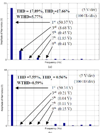
The all harmonic components in the load voltage of IS and SHE have been illustrated in Fig. 5.
(a)
(b)
Fig. 5. Harmonic analyses result for 11-level inverter: a) IS; b) SHE. By using SHE technique, it is aimed to obtain the same amplitude of load voltage in IS and to eliminate 3rd, 5th, 7th
and 9th harmonic orders. It has been achieved 0.839
modulation index by GA based SHE while modulation index of IS is 0.84. The peak value of fundamental component of load voltage is (0.8395) × (60) = 50.37 V for IS and (0.839) × (60) = 50.34 V produced by GA based SHE technique. These close values have proved that the harmonic analysis has been done under the similar conditions. When Fig. 5(a) and Fig. 5(b) are analysed, it can be concluded that the 3rd, 5th, 7th and 9th harmonic orders of SHE are almost
harmonic orders of IS respectively. In addition, general THD is reduced to 7.55 % from 17.89 % and THDe is
reduced to 0.56 % from 17.66 % by using SHE instead of IS. 0.56 % THDe value is almost zero, because THDe is
((V32 + V52 + V72 + V92)1/2)/V1 for 11-level inverter. In addition, WTHD value decreases to 0.59 % from 5.77 % thanks to the eliminated harmonics. These results have verified the effectiveness of proposed elimination method. B. Experimental Implementing of Proposed Multilevel Inverter
In this paper, selective harmonic elimination in multilevel inverter with reduced number of switches has been executed. GW-Instek GDS-1052 U oscilloscope has been used for measurements.
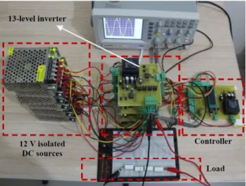
Experimental prototype of proposed multilevel inverter has been given in Fig. 6. Switching signals have been generated with PIC 18F4520.
Fig. 6. Experimental prototype of proposed multilevel inverter. 1) Harmonic Analyses of Experimental Results
The harmonic analyses of each level have been executed by processing of datum transferred from the oscilloscope. The harmonic analysis processes of experimental results have been started by taking of each data for IS and SHE in 7, 11, 13-level inverter.
Each measurement has been processed with MATLAB&Simulink blocks and workspace tool of MATLAB as seen in Fig. 7. In Fig. 7(a), data string dimension of which is 4000 × 1 have been formed in MATLAB and datum taken from the oscilloscope have been loaded to data string. Time string has included the time data between 0 s and 0.04 s. The tout string is the Simulink
sub-string composed from MATLAB.
Finally, datum of the load voltage obtained from the oscilloscope have been transferred to Simulink&Powergui tool. The harmonic analyses have been implemented with Powergui block that enables to configure FFT analysis tool, simulation Parameters etc.
2) Experimental Results
In Fig. 8, experimental load voltages in 11-level inverter have been presented for IS and SHE. As stated in before, 11-level inverter has five voltage steps and the amplitude of load voltage at fundamental frequency is 60 V for each switching technique. When compared Fig. 8(a) and
Fig. 8(b), it can be concluded that the fifth step is narrower than IS. Because, the calculated fifth switching angle (α5) is very close to π/2.
(a)
(b)
Fig. 7. Experimental harmonic analysis: a) MATLAB workspace tool; b) Simulink blocks.
It can be deduced by comparing Fig. 8(a) and Fig. 8(b) that the desired harmonic orders are obtained nearby zero.
(a)
(b)
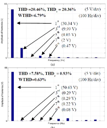
Fig. 8. Experimental load voltages for 11-level inverter: a) IS; b) SHE. Obtained experimental THD values for load voltages of 11-level inverter have been given in Fig. 9. While the first harmonic in IS technique is 50.34 V, SHE technique has generated 50.63 V load voltage and the eliminated harmonic components lower than 0.29 V. The third order harmonic is decreased to 0.29 V from 9.99 V, the fifth order harmonic is changed to 0.29 V from 0.03 V, seventh order harmonic is reduced to 0.22 V from 2 V, ninth order harmonic is declined to 0.08 V from 0.47 V. When decreasing of eliminated harmonic components and THDe is taken into
account, the deviation in 5th harmonic order is insignificant. The general THD values have been reduced to 17.55 % from 24.15 % for 7-level, to 7.58 % from 20.46 % for 11-level, to 8.08 % from 16.39 % for 13-level inverter by using GA based SHE technique.
(a)
(b)
Fig. 9. Experimental results in 11-level inverter: a) IS; b) SHE.
The THDe values have been diminished to 3.34 % from
21.26 % for 7-level, to 0.93 % from 20.36 % for 11-level, to 2.24 % from 16.32 % for 13-level by applying SHE technique to multilevel inverter with reduced number of switches. WTHD is step down to 2.53 % from 7.14 % for 7-level, to 0.63 % from 6.79 % for 11-7-level, 0.86 % from 5.30 % for 13-level. Obtained general THD, THDe and
WTHD values of SHE technique are too much lower than IS technique. These remarkable reductions in THD, THDe and
WTHD values demonstrate the efficiency of proposed SHE technique in multilevel inverter with reduced number of switches.
VI. CONCLUSIONS
In this paper, simulation and experimental studies of Isochronous Switching (IS) and Selective Harmonic Elimination technique (SHE) have been implemented to multilevel inverter with reduced number of switches. The proposed multilevel inverter structure has more compact design and has lower construction cost when compared to conventional multilevel inverter. By applying SHE technique to proposed multilevel inverter structure, it has been obtained the same modulation indexes in IS at all level between 5 and 13. Nonlinear SHE equations have been solved by Genetic Algorithm (GA) software coded in MATLAB. Results of 7, 11 and 13-level inverters controlled with both IS and SHE techniques have been obtained, 11-level inverter have been given in detail. Simulation and experimental results have clearly proved that IS and SHE techniques can be applied to proposed multilevel inverter structure. In addition, the presented results demonstrate that proposed GA based SHE technique can dramatically reduce desired consecutive odd number harmonic orders and gives better results in terms of THD, THDe and WTHD than the
IS technique.
REFERENCES
[1] H. Karaca, E. Bektas, “GA based selective harmonic elimination for multilevel inverter with reduced number of switches”, in Proc. World Congress on Engineering and Computer Science (WCECS 2015), San Francisco, USA, 2015, pp. 204–209.
[2] H. Karaca, E. Bektas, “Selective harmonic elimination using genetic algorithm for multilevel inverter with reduced number of power switches”, Engineering Letters, vol. 24, no. 2, pp. 138–143, 2016. [3] R. H. Baker, L. H. Bannister, “Electric Power Converter”, US Patent,
3867643, Feb. 1975.
[4] R. H. Baker, “Bridge Converter Circuits”, US Patent, 4270163, May. 1981.
[5] J. Rodriguez, J. S. Lai, F. Z. Peng, “Multilevel inverters: survey of topologies, controls, and applications”, IEEE Trans. Industrial Electronics, vol. 49, no. 4, pp. 724–738, 2002. DOI: 10.1109/TIE.2002.801052.
[6] E. Bektas, H. Karaca, “Harmonic minimization technique for multilevel inverter using cascaded H-bridge modules”, in Proc. (UNITEC 2015), Gabrovo, Bulgaria, 2015, pp. 139–143.
[7] L. M. Tolbert, J. N. Chiasson, Z. Du, K. J. McKenzie, “Elimination of harmonics in a multilevel converter with nonequal DC sources”, IEEE Trans. Industry Applications, vol. 41, no. 1, pp. 75–82, 2005. DOI: 10.1109/TIA.2004.841162.
[8] K. El-Naggar, T. M. Abdelhamid, “Selective harmonic elimination of new family of multilevel inverters using genetic algorithms”, Energy Conversion and Management, vol. 49, no. 1, pp. 89–95, 2008. DOI: 10.1016/j.enconman.2007.05.014.
[9] W. Fei, X. Du, B. Wu, “A generalized half-wave symmetry SHE-PWM formulation for multilevel voltage inverters”, IEEE Transactions on Industrial Electronics, vol. 57, no. 9, pp. 3030–3038, 2010. DOI: 10.1109/TIE.2009.2037647.
[10] J. R. Wells, X. Geng, P. L. Chapman, P. L. Krein, B. M. Nee, “Modulation-based harmonic elimination”, IEEE Trans. Pow. Electron., vol. 22, no. 1, pp. 336–340, 2007. DOI: 10.1109/TPEL.2006.888910.
[11] K. Yang, Q. Zhang, R. Yuan, W. Yu, J. Yuan and J. Wang, “Selective harmonic elimination with groebner bases and symmetric polynomials,” IEEE Trans. Power Electronics, vol. 31, no. 4, pp. 2742–2752, 2016. DOI: 10.1109/TPEL.2006.888910.
[12] J. N. Chiasson, L. M. Tolbert, K. J. McKenzie, Z. Du, “A unified approach to solving the harmonic elimination equations in multilevel converters”, IEEE Trans. Power Electronics, vol. 19, no. 2, pp. 478– 490, 2004. DOI: 10.1109/TPEL.2003.823198.
[13] S. Debnanth, R. N. Ray, “Harmonic elimination in multilevel inverter using GA and PSO: a comparison”, IEEE Students’ Conf. Electrical, Electronics and Computer Science, Bhopal, India, 2012, pp. 1–5. DOI: 10.1109/SCEECS.2012.6184789.
[14] M. H. Etesami, N. Farokhnia, S. H. Fathi, “Colonial competitive algorithm development toward harmonic minimization in multilevel inverters”, IEEE Trans. Industrial Informatics, vol. 11, no. 2, pp. 459–466, 2015. DOI: 10.1109/TII.2015.2402615.
[15] O. Bouhali, F. Bouaziz, N. Rizoug, A. Talha, “Solving harmonics elimination equations in multi-level inverters by using neural networks”, International Journal of Information and Engineering, vol. 3, no. 2, pp. 191–195, 2013. DOI:10.7763/IJIEE.2013.V3.296. [16] E. Babaei, S. H. Hosseini, “New cascaded multilevel inverter
topology with minimum number of switches”, Energy Conversion and Management, vol. 50, no. 11, pp. 2761–2767, 2009. DOI: 10.1016/j.enconman.2009.06.032.
[17] S. Camur, B. Arifoglu, E. Beser, E. K. Beser, “A novel topology for single-phase five-level inverter”, in Proc. 5th Int. Conf. (WSEAS/IASME 2015), Tenerife, Spain, 2015, pp. 314–319. [18] S. J. Park, F. S. Kang, M. H. Lee, C. U. Kim, “A new single-phase
five-level inverter employing a deadbeat control scheme”, IEEE Trans. Pow. Electron., vol. 18, no. 3, pp. 831–843, 2016. DOI: 10.1109/TPEL.2003.810837.
[19] G. Ceglia, V. Guzman, C. Sanches, F. Ibanez, J. Walter, M. Gimenez, “A new simplied multilevel inverter topology for DC-AC conversion”, IEEE Trans. Power Electronics, vol. 21, no. 5, pp. 1311–1319, 2006. DOI: 10.1109/TPEL.2006.880303.
[20] J. S. Choi, F. S. Kang, “Optimum structures of proposed new cascaded multilevel inverter with reduced number of components”, IEEE Trans. Ind. Electron., vol. 62, no. 6, pp. 3448–3459, 2015. [21] W.-K. Choi, F. Kang, “H-bridge based multilevel inverter using PWM
switching function”, in 31st Int. Telecommunications Energy Conf. (INTELEC 2009), Incheon, South Korea, 2009, pp. 1–5. DOI: 10.1109/INTLEC.2009.5351886.
switches and gate driver”, in 18th Iranian Conf. Electrical Engineering, Isfahan, Iran, 2010, pp. 784–789. DOI: 10.1109/IRANIANCEE.2010.5506968.
[23] H. Karaca, “A novel topology for multilevel inverter with reduced number of switches”, in Proc. World Congress on Engineering and Computer Science (WCECS 2013), San Francisco, USA, 2013, pp. 350–354.
[24] A. Farakhor, R. R. Ahrabi, H. Ardi, S. N. Ravadanegh, “Symmetric and asymmetric transformer based cascaded multilevel inverter with minimum number of components”, IET. Pow. Electron., vol. 8, no. 6, pp. 1052–1060, 2015. DOI: 10.1049/iet-pel.2014.0378.
[25] E. Babaei, S. Laali, “Optimum structures of proposed new cascaded multilevel inverter with reduced number of components”, IEEE Trans. Ind. Electron., vol. 62, no. 11, pp. 6887–6895, 2015. DOI: 10.1109/TIE.2015.2437330.
[26] K. K. Gupta, A. Ranjan, P. Bhatnagar, L. K. Sahu, S. Jain, “Multilevel inverter topologies with reduced device count: a review”, IEEE Trans. Power Electronics, vol. 31, no. 1, pp. 135–150, 2016. DOI: 10.1109/TPEL.2015.2405012.
[27] M. R. J. Oskuee, M. Karimi, S. N. Radanegh, G. B. Gharehpetian,
“An innovative scheme of symmetric multilevel voltage source inverter with lower number of circuit devices”, IEEE Trans. Ind. Electron., vol. 62, no. 11, pp. 6965–6973, 2015. DOI: 10.1109/TIE.2015.2438059.
[28] E. Babaei, S. Laali, Z. Bayat, “A single-phase cascaded multilevel inverter based on a new basic unit with reduced number of power switches”, IEEE Trans. Ind. Electron., vol. 62, no. 2, pp. 922–929, 2015. DOI: 10.1109/TIE.2014.2336601.
[29] T. Sag, M. Cunkas, “Multiobjective genetic estimation to induction motor parameters”, in Proc. Int. Aegean Conf. Electrical Machines and Power Electronics (ACEMP 2007), Bodrum, Turkey, 2007, pp. 628–631. DOI: 10.1109/ACEMP.2007.4510580.
[30] H. L. Liu, Y. P. Wang, “Solving constrained optimization problem by a specific-design multiobjective genetic algorithm”, in Proc. Fifth Int. Conf. Computational Intelligence and Multimedia Applications. (ICCIMA 2003), Xi'an, China, 2003, pp. 200–205. DOI: 10.1109/ICCIMA.2003.1238125.
[31] J. M. Mendes, “A comparative study of crossover operators for genetic algorithms to solve job shop scheduling problem”, WSEAS Trans. Computers, vol. 12, no. 4, pp. 164–173, 2013.