Miniaturized Fiber-Optic Transmission System for MRI
Signals
Omer Gokalp Memis,
1Yigitcan Eryaman,
1Orhan Aytur,
1and Ergin Atalar
1,2*
Conventional MRI instruments transmit received MRI signals through electrical cables. Although this design has proved to be effective over the years, we report a fiber-optic system that addresses the needs of recent developments in MRI technol-ogy. One of these technologies is phased array coils with a high number of elements, where total size of interconnections is a primary problem, and other problem is internal MRI coils, where there is a need for improvements in safety. The Miniature Fiber-Optic Transmission (FOT) System was developed to address these issues. The system consists of a receiver coil with active detuning, a low-noise preamplifier, and a laser diode connected to a photodetector with fiber-optic cabling. The overall noise figure of the system is lower than 1 dB. Total power consump-tion is 50 mW, and the device is switchable with another fiber-optic line, which can also control active detuning. A prototype device was tested in a GE 1.5 Tesla MRI scanner, and several images were acquired with a signal to noise ratio similar to coaxial cabling. We believe that this design will reduce the cabling problems of arrays and enable placement of internal coils into body cavities with no safety hazard to the patient, such as electrical shock or burns. Magn Reson Med 59: 165–173, 2008.© 2007 Wiley-Liss, Inc.
Key words: MRI; optical data transmission; MRI cabling; MRI RF coils
The primary motivation for this work was to construct an optical system capable of transmitting MRI signals with the highest possible signal-to-noise ratio (SNR). Such a device would make placement of a miniaturized internal (endoluminal) MRI coil possible with no safety risk to the patient. Another potential application for such a small-sized fiber-optic transmission system is the minimization of cabling problems in phased array coils with a high number of elements.
Internal MRI coils have been developed for many years. There are different sizes for several applications: intravas-cular (1,2), transesophageal (3), endourethral (4), and en-dorectal coils (5,6). The main reason for the interest in these devices is their ability to probe into the body further than external coils, yielding better SNR in the regions of interest.
Patient safety in MRI is defined by international stan-dards and is of the utmost importance. Although
interven-tional prototypes have been available for some time, the potential risks they pose to the patient have limited their widespread use and prevented their clinical use. Several researchers have worked to better analyze and estimate the actual risk, which primarily originates from radio fre-quency (RF) heating. RF heating stems from the interac-tions of the electromagnetic field with the metallic parts of the interventional device. Given the proximity of the in-terventional device to local tissue, the potential hazards from this kind of heating should not be underestimated. Recently, it has been reported that the tips of the wires are the regions where the highest heating occurs, although the amount of heating is a complex function of orientation and length factors (7–9). Theoretical models involving the spe-cific absorption rate (SAR) and the bioheat transfer equa-tion have been used (10) to better estimate the heating process.
Theoretical and experimental work on the heating around coaxial cables shows that the heating can be low-ered by limiting the size of coaxial sections and using chokes to interconnect these sections (11). Although this process does decrease the heating, it has also been shown that the chokes created new resonant fields with concen-trated electric fields. Recently, Weiss et al. have proposed using transformers between the coaxial cable sections and have developed a safer coaxial transmission line (12). However, these safe coaxial cable designs are still being investigated for clinical use.
The idea of using fiber optics rather than coaxial cables in MRI is a solution for this RF heating problem. Because the fiber itself forms a nonconductive path, it does not create excessive heat around its tips and does not have resonant sections where fields become concentrated. Thus, with regard to interventional device safety, using fiber-optic cables for connections would be less risky.
In fact, the idea of using fiber optics has already been proposed as a safer alternative in a different context: MR-guided interventional operations. During MR-MR-guided inter-ventional operations, tracking and localization of catheters and devices is crucial for success, for which passive and active methods are used. Briefly, passive methods use the artifacts generated from the interventional device, but have the disadvantages of relatively low spatial resolution and reduced speed compared with active methods (13). On the other hand, active methods involve tuned RF coils and, thus, require dedicated detuning mechanisms, usually in the form of leads and cables, which suffer from the RF heating problem. One solution that combines the benefits of active tracking with the safety of passive methods is a wireless detuning system by Wong et al. (14). Their work suggested using a fiber pigtailed photoresistor to lower the Q of the system and detune the coil when necessary, thus eliminating the need for electrical connections.
1Bilkent University, Department of Electrical and Electronics Engineering,
Ankara, Turkey.
2Johns Hopkins University, Departments of Radiology, BME and ECE,
Balti-more, Maryland.
Contract grant sponsor: NIH; Contract grant number: RO1RR15396. *Correspondence to: Ergin Atalar, Department of Electrical and Electronics Engineering, Bilkent University, 06800 Ankara, Turkey. E-mail: [email protected]
Received 14 March 2006; revised 30 September 2007; accepted 1 October 2007.
DOI 10.1002/mrm.21462
Published online in Wiley InterScience (www.interscience.wiley.com).
In addition to the safety factor, there is another area that may benefit from fiber-optic cabling, and that is parallel imaging. Similar to the rapid growth of interventional methods in MRI, multiple channel imaging has been an-other rapidly developing area. Recently, several research-ers presented papresearch-ers describing a 32-channel head coil (15), a 48-channel body/spine coil (16), and even a 96-channel MRI system (17), which indicate the advent of prospective MRI systems with more than 32 channels, which are now commercially available.
The fusion of fiber-optic technologies with these new, extreme multiple number of channels could result in a more reliable MRI scanner. Using fibers can eliminate some of the drawbacks of the current systems, such as the size of the bundle of coaxial cables or the safety issues with this bundle. A recent proposal featured an optical interconnect for multiple channel MRI systems (18), which is similar to what we proposed at ESMRMB’03 (19) and have been developing since that time. Although the main idea in these papers is the same, the technologies used by the investigators are different. Koste et al. used a fiber-optic modulator, whereas we have chosen a low-noise laser diode instead to couple the MRI signals to a laser. Both technologies offer the benefits of fibers: First, they do not contain coaxial cables; therefore, the risk of electrical shock or RF burns is nonexistent. Second, they are immune to the electrical interference that coaxial ca-bles experience, that is, the noise contributed by nearby electronics (mainly from switching). Fiber-optic cables are also free of any unbalanced currents or potential common ground problems. Last but not least, the use of fibers in a 96-channel MRI system will yield significant size reduc-tions in the interconnect region between the scanner hard-ware and the controller/receiver hardhard-ware.
MATERIALS AND METHODS
Naturally, the use of fiber-optic technologies in MRI would require the addition of new steps and circuitry to the basic operation scheme. However, care must be taken while designing such circuitry, as MRI compatibility is an ex-tremely important issue.
There were some points we considered throughout the design stage. Although some limitations are inherent to the magnetic resonance technology itself, there are other lim-itations associated with currently available commercial products and safety.
First, the main and most important limitation is the prohibition of some materials in MRI. Ferromagnetic
ma-terials, which have a large and positive susceptibility to an external magnetic field (20), exhibit a strong attraction to magnetic fields. Because MRI heavily depends on the fun-damental properties of nuclear spin under a strong mag-netic field, ferromagmag-netic materials in MRI pose serious hazards to the patient, operator, and scanner, primarily due to the strong force ferromagnetic materials undergo in the superconductive magnet. In addition to the force ex-perienced, highly magnetic materials also create addi-tional problems: the disturbance of the magnetic field in-side the MRI magnet, which leads to artifacts and image quality degradation, and the functional failure of the com-ponents, which are sensitive to external magnetic fields such as inductors and optical isolators.
Second, the noise factor and SNR are other limitations in MRI. The MRI signals, when received by the detection coil, are weak in nature. Therefore, it is essential that the noise contribution while transporting and processing the signals is kept to a minimum level, and ultra–low-noise pream-plifiers (ULNAs) with sufficient gain should be placed close to the coil.
Third, although not a strict requirement, small size is a great advantage, in terms of patient comfort in interven-tional imaging, and less volume and size for the receiver array in parallel imaging.
Fourth, a constraint similar to size is power. The design should consume the least power possible, to conserve battery capacity, reduce heating, and reduce the total power consumption in the parallel imaging array.
The fiber-optic prototype was designed based on these requirements and recommendations. It consists of the fol-lowing sections, each of which is either modified or com-pletely new compared with the current designs (see Fig. 1): coil, together with matching and detuning circuitry; trans-mitter: preamplifiers, laser diode, and matching circuitry, power and control circuitry; and receiver and external control circuitry.
The Coil
The coil is the starting point where electromagnetic echoes of the RF excitation pulse are received and are converted to low-power electrical MRI signals. The nature of these signals is narrowband in the very high frequency (VHF) band (30 –300 MHz). This eliminates any need for broad-band designs, and allows the use of simple L-match tech-niques.
In our design and experiments, a home-made endorectal coil was used, together with appropriate matching and
FIG. 1. Block diagram of the fi-ber-optic transmission system: The coil with detuning circuitry, ultra–low-noise preamplifier and laser diode with appropriate matching connected to the re-ceiver. The power is supplied by a battery through the power and control circuitry.
passive or active detuning circuits, depending on the ex-periment.
The endorectal coil was designed as a cylindrical sub-strate stabilized on a rectangular base. The cylinder had a diameter of 23 mm, a length of 143 mm, and was made of white plastic. The base, which held the matching and detuning circuitry with the connector, was 98 mm (L)⫻ 30 mm (W)⫻ 5 mm (D).
The coil consisted of a solid copper wire of 1 mm diam-eter, which was placed on the surface of the cylindrical plastic, with parallel sides of 136 mm in the longitudinal direction of the cylinder, and perpendicular sides passing through the entire diameter (23 mm) in the axial direction. The entire cylinder—including the coil—was then covered with a heat-shrink tube to ensure safety and isolation from the environment.
The coil was tuned for operation at 63.85 MHz using nonmagnetic chip capacitors by series-shunt configura-tion. The exact values of these capacitors are determined experimentally by a vector network analyzer (HP/Agilent 3753D). In addition to the matching circuit, there is a second element that is responsible for detuning. Among the two possible detuning schemes, active detuning was preferred over passive detuning, whenever possible. Ac-tive detuning was implemented using a transmission line to transform the low-impedance of active PIN diodes to the resonant inductance value (21). A wire, 23 mm in length, was placed between the shunt capacitors and the PIN diode(s), which acted as a transmission line. Note that, as the coil was matched to 50 ⍀ with the capacitors, the transmission line did not alter the impedance value seen by the preamplifiers.
The coil was designed to work as an active or passive detuning device, just by adding or removing a single PIN diode. This was required for comparison purposes: in con-ventional operation (coaxial cables), the system used ac-tive detuning, whereas the fiber-optic system experi-mented with the passive or active methods. Thus, the resulting images obtained from the MRI receiver were comparable.
When the coil was used with the optical transmission system and active detuning, an additional piece was placed between the coil and transmitter: This piece was responsible for injecting current to the coil (for detuning) and consisted of a phototransistor (by Industrial Fiber Optics Inc., Tempe, AZ) connected between a power sup-ply and the signal path.
A final point regards the use of balanced-to-unbalanced converters (baluns). Although these converters must be used to prevent unbalanced currents in conventional coil designs, fiber-optic cables, which are nonconductive in nature, do not suffer from unbalanced current problems. Thus, baluns are not required for fiber-optic designs. Transmitter
After the weak echoes are captured by the coil, the signals require some basic processing before they can be con-verted into optical signals. The portion of the prototype responsible for preprocessing and optical conversion is the transmitter; and it consists of preamplifiers, followed by the laser diode with corresponding bias and matching circuitry.
Preamplifier
The MRI signals at the receiving coil are extremely low power and will have been already affected by the noise contribution from the resistive coil before arriving at the preamplifier. The primary reason to use preamplifiers be-fore any optical conversion is to preserve the SNR at the output of the coil as much as possible. To this end, ULNA must be used in the initial stages to boost the signal, preserving SNR in the later stages of device deployment. A measure of SNR degradation, the noise figure, is defined as:
NF⫽ 10log
冉
SNRin SNRout冊
.
An ULNA incorporates a noise figure lower than 1 dB, which means that the output SNR should be at least 0.8 times the input SNR. In our design, we used Infineon BFP420, which is a high fTtransistor with very low noise
properties, has well-documented parameters and wide commercial availability. BFP420 was biased properly, and it was loaded such that it experiences a predefined reflec-tion with lowest noise (22).
Although transistors with high fTprovide a rather high
gain for the VHF band, their maximum stable gain is usu-ally lower to prevent oscillations. Thus, resistive loading was used for interstage stability.
For the DC biasing and RF coupling of transistors, in-ductors and capacitors were used frequently. Inin-ductors, acting as RF chokes (RFCs), were selected as the highest nonmagnetic value available, 820 nH, and were mostly used as pairs. Similarly, capacitors of 1 nF were chosen for AC coupling purposes and 100 nF for stabilization (pre-vention of undesired feedback and fluctuations). Addition-ally, for each decoupling capacitor of 100 nF, an additional 1 nF was placed in parallel. This configuration increases the decoupling efficiency, especially at high frequencies.
Laser Diode Circuitry
The laser diode circuitry is the component responsible for the conversion of MR signals from the electrical to the optical state. The circuitry is placed just after the pream-plifiers in the RF signal path of the fiber-optic MRI probe. The reason this circuit is preceded by preamplifiers is purely noise performance. The electrical-optical-electrical (E-O-E) conversion process, part of which is the laser di-ode circuitry, is inherently associated with a loss in the transmitted power. When combined with the higher noise levels introduced in this section (i.e., intensity and shot noise), this attenuation can lead to disastrous results: mas-sive SNR degradation or even the disappearance of signal beneath the noise. Adding preamplifiers prevents this problem, provided that the gain is sufficient enough to move the signal away from the noise floor even after atten-uation.
The laser diode circuitry consists of an L-match section, a bias-tee, and the laser diode itself (see Fig. 2). The L-match is responsible for the L-matching of the low imped-ance laser diode to the high impedimped-ance output of the preamplifier. The bias-tee combines the RF signal with the
appropriate DC current injection required to bias the laser. Finally, the laser diode is at the core of the electrical-to-optical conversion process, also holding the micro-lens to couple the generated optical energy to the fiber.
The laser was custom-made by Applied Optoelectronics Inc. and housed in a coaxial package (C5). It was a multi-quantum-well distributed feedback laser designed for an-alog modulation in cable TV return path applications and was fitted with an SC connector with angular physical contact (APC) polish.
The central wavelength of the laser is 1.55m, with an optical power of 2 mW at an operating current of 30 mA. The threshold current is 12–13 mA, depending on the particular sample, and the responsivity is around 0.12– 0.13 W/A. A measure of its noise characteristics, the rela-tive intensity noise (RIN), range from ⫺153 dB/Hz to ⫺155 dB/Hz, both of which are very low values. RIN is the measure of noise that arises from optical effects in the laser diode (23), defined as:
RIN⫽ 10log
冉
具Popt2 典
Popt
冊
,
where具Popt2 典 is the mean square optical intensity
fluctua-tion in a 1 Hz bandwidth at a specified frequency, and Popt
is the average optical power.
In low-noise lasers, reflections must be avoided as much as possible, as they increase the noise level. One way to reduce reflections is to use an APC connector with angled reflections. Another common way is to use optical isola-tors that are not MRI compatible because that rely on the Faraday effect to work, which is magnetic field-dependent (24).
Although the laser was custom-built based on our spec-ifications, modification of the lasers was eventually re-quired. Removal of the optical isolator and realignment of
the fiber were done in our optic labs using an XY-transla-tion stage (New Focus, San Jose, CA), a Z-translaXY-transla-tion stage (NewPort, Irvine, CA), a rotational stage (NewPort), and dual-fiber alignment stages (NewPort). The power mea-surement during realignment was achieved using a hand-held power meter from New Focus. A metal epoxy was used for the fixation of fiber and diode modules.
Power and Control Circuitry
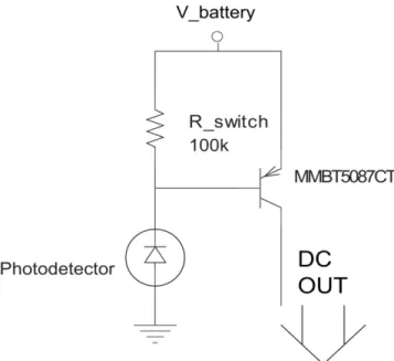
The power and control circuitry is responsible for supply-ing power to the rest of the transmitter and switchsupply-ing it when necessary. This section is designed so as not to contain any RF power and is not a part of the signal path. This circuit includes another fiber-optic line (control fiber) connected to a photodetector diode (PD). A photo-detector diode is a device that acts similar to an optically controlled current source.
The photodiode is connected to a PNP transistor in a Darlington configuration (see Fig. 3). When an external source activates the photodiode, it acts as a current source and conducts a known amount of current, which generates a voltage greater than the base-emitter on the voltage (VBE(on)) of the PNP transistor. Dictated by Kirchhoff’s laws,
the current flowing through the resistance Rswitch⫽ 100 k⍀
is only part of the current conducted by the diode, the rest of which becomes the base current of the transistor. This base current is adjusted to be sufficient enough to put the transistor into saturation, providing⬃2.9 V to the rest of the device, including the amplifiers and the laser diode.
The photodiode was manufactured by Industrial Fiber Optics Inc. (Tempe, AZ) and is a high-speed, low-cost photodetector in a plastic housing. It is sensitive to a wavelength range from 400 nm to 1100 nm, with a peak responsivity of 0.4A/W around 880 nm. It is connected to a light emitting diode (LED) operating at 870 nm and
FIG. 3. Power circuitry: Drawing sufficient current from the photo-detector makes PNP transistor go into saturation; giving 2.9 V to the rest of the circuit.
FIG. 2. Schematics of the laser diode and relevant circuitry: The power matching circuit is followed by a bias-tee in the middle of which is the laser diode.
matching the peak responsivity. The connection is through a 1000m multimode fiber.
The PNP transistor in the Darlington configuration was a Fairchild MMBT5087CT. This transistor is a general-pur-pose amplifier with a minimum DC gain (hFE) of 250. Its
high gain and low collector– emitter saturation voltage (VCE(sat): maximum 0.3 V, measured 0.1 V) made it an
excellent transistor for switching the transmitter on and off.
Complete Schematics of the Transmitter
Although each component of this method was defined, there was more than one way to combine these compo-nents. Thus, there were two different schematics for the transmitter: high-current and low-current designs; and, as in all designs, there was a tradeoff.
The reason low current was preferable to the high cur-rent was primarily in how the power would be supplied. Battery-supplied power has always had limits that were not explicitly stated in the datasheet, one of which is the internal resistance. The internal resistance of a cell is the physical limit on the maximum current it can supply. Therefore, even though a battery is rated 25 mAh, it might not produce 20 mA at all. This was a very solid reason to
design circuitries to work with low-current and high-volt-age ratings.
The problems with using high-voltage/low-current de-signs were the increased risk of oscillations due to the extra feedback and the increased switching time. High-voltage designs usually fed the biasing current through more than one active device on the signal path, that is, a transistor, and a laser diode. Moreover, these designs used RFC to route the RF signal correctly. However, RFC are not perfect, and pass a very small part of the RF power, which would result in feedback that may result in oscillations in such a high-gain system. RFC are also inductor-based com-ponents: Combining the slowness of RFC with the elec-tron-hole pair generation and recombination processes in semiconductors, the switching time of the transmitter dra-matically increased. Considering the tradeoff between the two different design approaches, we decided to proceed with the low-current design that had the higher voltage rating (3 V) required (see Fig. 4).
Receiver and External Control Circuitry
The receiver and external control circuitry are the compo-nents connected to the MRI scanner. This forms a rather small section with simple circuits with their own power
FIG. 4. Overall schematics for 3 V design: The same current biases both the laser and the preampli-fier.
supply. The optical fiber constitutes the receiver’s only connection to the transmitter and coil.
Receiver
The MRI signals, after being coupled to the optical beam in the fiber, are then transmitted to the receiver. The main responsibility of the receiver is to convert optical signals back to electricity, and it uses a special photodetector.
An analysis of the laser beam that falls on the PD reveals that the envelope of the beam consists of two components, the one generated by MRI signals and the one generated by the DC biasing current of the laser diode. The current that the photodetector generates is actually the sum of these components converted. As the demodulation of the optical carrier is performed internally by the photodetector, the only circuitry needed is a bias-tee to separate these two components (see Fig. 5).
The photodetector used in this component was a high-speed diode by JDS Uniphase (West Tranton, NJ). This photodiode is a 100-m diameter InGaAs photodetector in a plastic housing with an SC receptacle. It has a peak responsivity (minimum⌫PD⫽ 0.7A/W, measured ⌫PD⫽ 0.8
A/W) at 1550 nm, matching the wavelength of the laser. The photodetector has a 2 GHz bandwidth.
Together with the laser, the E-O-E conversion system showed an attenuation of 19.6 dB.
External Control Circuitry
The external control circuitry is the complement of the power and control circuitry of the transmitter. The first component consists of a fiber pigtailed LED (100 Mbps IR LED; Industrial Fiber Optics, Inc.) and corresponding bi-asing resistors. The LED was selected to mate perfectly with the 1000-m fiber.
The second component uses the same LED on the signal path. This strategy accomplishes two goals: It allows the coil to be recognized by the scanner with its diode char-acteristics, and it signals the time interval during which the coil should be turned off. During testing, it was noted that the combination of this LED and the phototransistor in the coil would yield a current gain of approximately 1, transferring the injected current (⬃10–20 mA) from the scanner to the coil optically.
Noise Calculations
Because the most important aspect of this design is to preserve the SNR as much as possible, the different types of noise encountered should be identified and the noise power should be estimated. The three different kinds of noise to be accounted for and dealt with are thermal noise,
shot noise, and laser intensity noise. Thermal noise is
created by ohmic resistances, shot noise is created by the quantum nature of current carriers (electrons), and laser intensity noise is created by the laser diode of the trans-mitter.
Knowing the sources of noise, together with the compo-nents of the prototype and their corresponding parameters, noise calculations of the overall design could be per-formed. First, the noise power per Hertz had to be calcu-lated, PLIN,laser⫽ 10RIN/10ILD2RL ⫽ 3.56 ⫻ 10⫺15mW/Hz, PShot,laser⫽ 2eRLILD ⫽ 2.40 ⫻ 10⫺16mW/Hz, PShot,PD⫽ 2eRLIPD ⫽ 6.40 ⫻ 10⫺18mW/Hz,
where ILDis the DC bias current of the laser diode, IPDis the
DC current on the photodetector, and RLis the load
resis-tance (50 ⍀). Using these powers, the noise level of the preamplifier was designed to be:
NFpreamp⫽ 0.88dB.
The gain of each section, assuming perfect match among components,
Apreamp⫽ 50dB,
ALD⫺PD⫽ ⌫LD2⌫PD2 ⫽ ⫺ 19.6dB
was also important in the calculation of the overall noise figure.
It is important to note that the noise of the first preamp dominates the noise level of the overall system. The for-mula for the final noise factor of cascaded stages is:
Ftotal⫽ F1⫹ F2⫺ 1 A1 ⫹ F3⫺ 1 A1A2 ⫹ F4⫺ 1 A1A2A3⫹ . . .
and Ftotal is primarily affected by F1, given that the first
stage amplification (A1) is large enough. Combining the
calculated values, we obtained
Ftotal⫽ 1.23,
which demonstrated that the noise figure of the system FIG. 5. Schematics of the receiver: The photodetector converts
optical energy into electrical signals. The bias-tee separates DC component of the signal from radiofrequency component.
NFtotal⫽ 0.92dB,
was lower than the targeted limit of 1 dB.
RESULTS
The experimental results we have obtained can be divided into two categories: offline measurements and online mea-surements. Offline measurements correspond to the exper-iments using laboratory equipment away from the MRI scanner, whereas online measurements refer to the data acquired in the MRI chamber. Note that, because only the high-voltage/low-current design was built into a proto-type, all measurements and experimental results were gathered by this 3 V design.
Offline Measurements
One important measurement was the insertion gain, S21, which tested the signal path, including the amplifiers and E-O-E conversion. The instrument used for measurement was an HP/Agilent 8753D Vector Network Analyzer. In addition, before any data acquisition took place, full two-port calibration had been performed for accuracy in the frequency range of 63 MHz to 65 MHz. The power range was adjusted to ⫺65 to ⫺50 dBm, with an active port power of⫺60 dBm. This port power was an optimal value, because since higher levels saturated the device and lower levels increased the uncertainty (noise) in the measure-ment. The resulting transmission data were viewed on a rectangular plot of S21 (dB) versus frequency. This mea-surement showed an overall gain of 33 dB, suggesting an amplifier gain of 52.6 dB.
To measure the noise figure, an HP/Agilent 8970 Noise Figure Meter with an HP/Agilent 346B Noise Source was used. Using a noise figure meter, the noise figure was recorded as 0.88 dB, NF ⫽ 0.88 dB, with the amplifier connected to the original laser. Later, when the laser was modified and corresponding noise levels increased, new measurements were required. They yielded similar results, indicating the gain in the preamplifiers was sufficient to boost the signals away from the higher noise levels, NF⫽ 0.91 dB.
Because the transmission system was composed of a nonlinear E-O-E conversion circuitry, the linear range of the device was evaluated. An Agilent Spectrum Analyzer was used to perform third-order intercept (IP3) measure-ments. The overall system showed an output IP3 of ⫺12.5 dBm, which corresponds to an input IP3 of IIP3 ⫽ ⫺45 dBm. Combining the noise floor and IIP3, one can calculate spurious free dynamic range (SFDR), which is defined as two-thirds the difference between input third-order intercept and noise floor (25). The noise floor is the noise power per Hertz on a 50 ⍀ resistor, and it is 4*; kB*T⫹ NF ⫽ ⫺168 dBm/Hz ⫹ 1 dB. Corresponding SFDR
in 1 Hz bandwidth is 2/3*(IIP3⫺ Noise floor) ⫽ 81.3 dB. For a 500 Hz bandwidth, the SFDR is 63.3 dB.
Online Measurements
Online experiments were performed in the MRI chamber using actual medical equipment. The MR device used
throughout the experiments was a 1.5 Tesla device, man-ufactured by General Electric. In each experiment, there were at least two different measurements: one with the coil connected to a coaxial cable using active detuning, and the other with the fiber-optic system using passive detuning (Fig. 6).
One point that should be noted is that, whenever the fiber-optic system was used for interconnection, an attenu-FIG. 6. Images from the experiments with similar signal-to-noise ratio. a: Coaxial. b: Fiber optic: attenuation ⫽ 30 dB. Identical imaging parameters were used. Prescan tuning variables including transmit gain and operating frequency were kept constant.
ator had been placed between the receiver and internal amplifier of the MR scanner. This was a precaution to avoid saturation or harm to the sensitive preamplifier of the MRI instrument.
The imaging parameters were set to the following val-ues: matrix⫽ 256 ⫻ 256, TR ⫽ 10,000 ms, TE ⫽ 15.4 ms, field-of-view (FOV)⫽ 16 cm ⫻ 16 cm, number of slices ⫽ 7, and slice thickness⫽ 3.5 mm. A home-made, single-turn, endorectal coil was used (136 mm long, 23 mm wide). Active decoupling was achieved by a PIN diode.
The object to be scanned was a phantom that consisted of a plastic bucket filled with water, 30 cm deep, with the coil inside a cylindrical gap in the middle of the bucket.
In obtaining the images, the procedure was to connect the coil with a coaxial cable and obtain a three-dimen-sional volumetric image from which the imaging parame-ters, including FOV and number of slices, were adjusted. Then, an image was acquired using the same setup, after which the coaxial was replaced with the fiber-optic system and active tuning was converted to passive. Later, a series of measurements were performed, during which the level of attenuation was decreased step-by-step to acquire the best image.
From the images, SNR values were calculated by taking the average signal values from the same region and sam-pling noise from the farther regions. As the pictures sug-gest, the signal and noise levels are elevated in the FOT system (due to the inherent gain) but the SNRs of the images are at the same level, indicating conservation of the received MRI signals.
DISCUSSION AND CONCLUSIONS
During this project, a fiber-optic MRI probe has been pro-posed, designed, and developed. The aim of this work was to extend interventional imaging and parallel imaging techniques; both of which have promising futures, but suffer from the limitations of current technologies.
The prototype incorporates a fiber-optic path to connect the coil to an MRI scanner, through which the received MRI signals are transmitted. Moreover, the probe is de-signed to be an ultra–low-noise system with minimal SNR degradation, which ensures the signals’ integrity. Finally, the power consumption is low enough to be operated for several hours with a battery as small as the device.
The device was tested in a 1.5T GE MRI scanner. Several images have been acquired that have SNR values compa-rable to images obtained by coaxial cables. The images also showed the erroneous components of the device and have led to modifications in the prototype to achieve better images.
The first problem was in the laser itself. The optical isolator inside malfunctioned, resulting in image degrada-tion. It has been reported that optical isolators are mag-netic, and thus their use in MRI may result in both func-tional and physical problems. Funcfunc-tionally, a significant reduction in SNR is very possible; the misalignment of the isolator due to the strong external magnetic field may block the optical path physically. Therefore, the isolator had to be removed, even though this led to increased laser intensity noise.
Another problem that the preliminary images suggest was insufficient passive decoupling. First, passive decou-pling alone resulted in a loss of uniformity of the main B0
field. This effect showed itself as overly bright or dim spots in the images when compared with the ones obtained with coaxial cables. A consequence of this failure was the in-creased amount of RF power fed to the sensitive pream-plifier, worsening its low noise characteristics over time, and eventually burning the preamplifier.
The solution to the collapse of passive detuning was to use active detuning. However, this required a dedicated control mechanism with precise timing. Fortunately, MRI scanners are equipped with this circuitry and this timing can be transmitted optically to the coil by means of an extra fiber. Using active decoupling solved the problems due to passive decoupling, and increased the lifetime of the device considerably.
With regard to the nonlinearity of the transmission sys-tem, the system performance was acceptable for the imag-ing protocol that we have used in performance testimag-ing. As dynamic range measurements have indicated, measured SFDR of the fiber-optic transmission system will be enough for some moderate dynamic range (50 dB) se-quences; however, it might also be inadequate for very demanding high dynamic range signals, especially 3D se-quences might require approximately 100 dB of dynamic range (26,27). Compression might arise with high input signals and it might cause image artifacts if they are not corrected (28). Previous studies have suggested adding circuits to compress the signal before analog/digital con-version (29) with the aim of reducing quantization noise in high signal producing sequences such as three-dimen-sional sequences. In this technique, the compression is corrected digitally with nonlinear mapping and the re-quired linearity is restored. Alternatively, parallel image acquisition can be used to increase dynamic range (30). Although we have not implemented it, similar techniques may be adapted to our system and the unwanted nonlin-earity of the optical circuit can be prevented or corrected. There are some possible enhancements to the prototype that could greatly increase the benefits. For parallel imag-ing, the addition of frequency division multiplexing of different channels is a possible improvement. This may eliminate the need for a dedicated laser and fiber-optic line for each channel, decreasing the size, power consumption, and cost significantly. Although there are possible prob-lems with this configuration, such as the intermodulation caused by nonlinearity, they can be avoided with the op-timization of channels per laser and sophisticated design techniques.
The most beneficial improvement for interventional im-aging would be a reduction in size. Integrated circuit so-lutions with embedded laser diodes are possible, which would decrease the size substantially— even to the small size required for intravascular applications. Furthermore, photovoltaic power converters can be used to supply power externally with a laser rather than using a bulky battery, and making the prototype virtually microscopic. Another enhancement would be to lower power consump-tion. Reduction of power consumption not only means smaller battery sizes, but may also enable the use of
smaller power generation devices, such as piezoelectric material that can convert mechanical energy to electricity. In concert with the development of more sophisticated MRI technologies, it is obvious that more sophisticated MRI scanners and probes will be designed and imple-mented. Our prototype was designed to address this emerging need, and the proof-of-principle tests have been conducted successfully. Although there are problems that should be solved before commercialization, we believe that this design and prototype is a very strong candidate to address the needs of interventional MRI.
REFERENCES
1. Ocali O, Atalar E. Intravascular magnetic resonance imaging using a loopless catheter antenna. Magn Reson Med 1997;37:112–118. 2. Martin AJ, McLoughlin RF, Chu KC, Barberi EA, Rutt BK. An
expand-able intravenous RF coil for arterial wall imaging. J Magn Reson Imag-ing 1998;8:226 –234.
3. Shunk KA, Lima JA, Heldman AW, Atalar E. Transesophageal magnetic resonance imaging. Magn Reson Med 1999;41:722–726.
4. Quick HH, Serfaty J-M, Pannu HK, Genadry R, Yeung CJ, Atalar E. Endourethral MRI. Magn Reson Med 2001;45:138 –146.
5. Schnall MD, Lenkinski RE, Pollack HM, Imai Y, Kressel HY. Prostate: MR imaging with an endorectal surface coil. Radiology 1989;172:570 – 574.
6. Susil RC, Krieger A, Derbyshire JA, Tanacs A, Whitcomb LL, Fichtinger G, Atalar E. System for MR image-guided prostate interventions: canine study. Radiology 2003;228:886 – 894.
7. Konings M, Bartels LW, Smits HF, Bakker CJ. Heating around intravas-cular guidewires by resonating RF waves. J Magn Reson Imaging 2000; 12:79 – 85.
8. Nitz WR, Oppelt A, Renz W, Manke C, Lenhart M, Link J. On the heating of linear conductive structures as guide wires and catheters in interventional MRI. J Magn Reson Imaging 2001;13:105–114. 9. Armenean C, Perrin E, Armenean M, Beuf O, Pilleul F, Saint-Jalmes H.
RF-induced temperature elevation along metallic wires in clinical mag-netic resonance imaging: influence of diameter and length. Magn Reson Med 2004;52:1200 –1206.
10. Yeung CJ, Susil RC, Atalar E. RF safety of wires in interventional MRI: using a safety index. Magn Reson Med 2002;47:187–193.
11. Ladd ME, Quick HH. Reduction of resonant RF heating in intravascular catheters using coaxial cables. Magn Reson Med 2000;43:615– 619. 12. Weiss S, Vernickel P, Schaeffter T, Schulz V, Gleich B. A safe
trans-mission line for interventional devices. Proceedings of the 5th Inter-ventional MRI Symposium. Available at: http://www.uni-leipzig.de/ radiol/start/archiv/5thinterventional/Abstracts.htm, 2004.
13. Wacker FK, Reither K, Branding G, Wendt M, Wolf K-J. Magnetic resonance-guided vascular catheterization: feasibility using a passive tracking technique at 0.2 tesla in a pig model. J Magn Reson Imaging 1999;10:841– 844.
14. Wong EY, Zhang Q, Duerk JL, Lewin JS, Wendt M. An optical system for wireless detuning of parallel resonant circuits. Magn Reson Med 2000;12:632– 638.
15. Wiggins GC, Triantafyllou C, Potthast A, Reykowski A, Nittka M, Wald LL. A 32 channel receive-only phased array coil for 3t with novel geodesic tiling geometry. Proceedings of the International Society of Magnetic Resonance in Medicine 13th Scientific Meeting (ISMRM’05), 2005.
16. Matschl V, Reykowsky A, Jahns K, Hergt M, Fischer H. 48 channel body/spine matrix coils for 3 tesla. Proceedings of the International Society of Magnetic Resonance in Medicine 13th Scientific Meeting (ISMRM’05), 2005.
17. Wiggins GC, Potthast A, Triantafyllou C, Lin F, Benner T, Wiggins CJ, Wald L. A 96-channel MRI system with 23- and 90-channel phase array head coils at 1.5 tesla. Proceedings of the International Society of Magnetic Resonance in Medicine 13th Scientific Meeting (ISMRM’05), 2005.
18. Koste GP, Neilsen MC, Tolliver TR, Frey RL, Watkins R. Optical MR receive coil array interconnect. Proceedings of the International Society of Magnetic Resonance in Medicine 13th Scientific Meeting (ISMRM’05), 2005.
19. Memis OG, Aytur O, Atalar E. Optical transmission of MRI signals: a safe alternative for internal MRI probes. Proceedings of the European Society of Magnetic Resonance in Medicine and Biology 20th Scientific Meeting (ESMRMB’03), 2003.
20. Cheng DK. Field and wave electromagnetics. USA: Addison-Wesley Publishing Company, 1992.
21. Edelstein WA, Hardy CJ, Muller OM. Electronic decoupling of surface-coil receivers for NMR imaging and spectroscopy. J Magn Reson 1985; 67:156 –161.
22. Gonzales G. Microwave transistor amplifiers: analysis and design. Up-per Saddle River, StateNJ: Prentice Hall, 1997.
23. Agilent Technologies. Lightwave signal analyzers measure relative in-tensity noise: product note 71400-1. Santa Clara, StateCA: Agilent Technologies, 2000.
24. Saleh BEA, Teich MC. Fundamentals of photonics. New York: Wiley, 1991.
25. Chang K. RF and microwave wireless systems. New York: Wiley, 2000. 26. Elliott MA, Insko EK, Greenman RL, Leigh JS. Improved resolution and signal-to-noise ratio in MRI via enhanced signal digitization. J Magn Reson 1998;130:300 –304.
27. Behin R, Bishop J, Henkelman RM. Dynamic range requirements for MRI. Concepts in magnetic resonance Part B: Magn Reson Eng 2005; 26B:28 –35.
28. Lufkin RB, Sharpless T, Flannigan B, Hanafee W. Dynamic-range com-pression in surface-coil MRI. AJR Am J Roentgenol 1986;147:379 –382. 29. Kose K, Endoh K, Inouye T. Nonlinear amplitude compression in magnetic resonance imaging: quantization noise reduction and data memory saving. IEEE Aerospace and Electronic Systems Magazine 1990;5:27–30.
30. Otake Y, Kose K, Haishi T. A solution to the dynamic range problem in MRI using a parallel image acquisition. Concepts in Magnetic Reso-nance Part B: Magn Reson Eng 2006;29B:161–167.