Method to enlarge the hologram viewing window
using a mirror module
Hoonjong Kang Bilkent University
Department of Electrical and Electronics Engineering
Bilkent Ankara, 06800 Turkey
and
Nihon University
Department of Electronics and Computer Science 7-24-1 Narashinodai Funabashi-shi, Chiba 2748501 Japan E-mail: [email protected] Naoyuki Ohmura Takeshi Yamaguchi Hiroshi Yoshikawa Nihon University
Department of Electronics and Computer Science 7-24-1 Narashinodai Funabashi-shi, Chiba 2748501 Japan Seung-Cheol Kim Eun-Soo Kim Kwangwoon University
Department of Electronic Engineering 3D Display Research Center
447-1 Wolgye-Dong, Nowon-Gu Seoul 139-701
Korea
Abstract. A liquid crystal panel for a video projector is often used for holographic television. However, its pixel size and pixel number are not enough for practical holographic 3-D display. Therefore, a multipanel configuration is generally used to increase the viewing window and dis-played image size, and many spatial light modulators should be used in them. We propose a novel method to increase the viewing window of a holographic display system. The proposed method, which is imple-mented by using a mirror module and 4-f lens set, is to reconfigure the beam shape reflected by a spatial light modulator. The equipment is applied to a holographic display system, which has only a single spatial light modulator; a hologram could be displayed in a wider viewing win-dow by the equipment than that of the conventional method. By the proposed method, the resolution of the reconfigured spatial light modu-lator has double resolution in the horizontal direction. Inversely, the ver-tical resolution is decreased. Even if the verver-tical resolution is decreased, a viewer could get 3-D effect because humans get more 3-D information in the horizontal direction. We have experimented using a liquid crystal on silicon共LcOS兲, whose resolution is 4096⫻2160 pixels. The reconfig-ured resolution by the mirror module is 8192⫻1080 pixels. From the experiments, the horizontal viewing window is almost two times wider than that without the mirror module. As a result, the hologram can be observed binocularly. © 2009 Society of Photo-Optical Instrumentation Engineers. 关DOI: 10.1117/1.3180869兴
Subject terms: viewing window; Fresnel hologram; holographic display; mirror module; 4-f lens system.
Paper 080974R received Dec. 16, 2008; revised manuscript received May 14, 2009; accepted for publication May 22, 2009; published online Jul. 30, 2009. This paper is a revision of a paper presented at the SPIE conference on Practical Holography XXII: Materials and Applications, January 2008, San Jose, California. The paper presented there appears共unrefereed兲 in SPIE Proceedings Vol. 6912.
1 Introduction
The real-time holographic video display system 共Holo-Video兲 developed at MIT1
can display tens of holographic images in a second. The Holo-Video uses an acousto-optic modulator 共AOM兲 or liquid crystal display 共LCD兲 as the spatial light modulator共SLM兲. The AOM method was pro-posed by Professor Benton’s group at MIT Media Laboratory.1This method sacrifices the vertical parallax to realize high-speed computation. In order to make the propagating fringes in the crystal appear stationary, it needs to use mechanical scanning. On the other hand, the optical system with an LCD does not require such mechanical scanning.2How to increase the hologram viewing window is one of the major issues in the research field of holo-graphic television, because the viewing window is usually dependent on the SLM. There are several ways to solve this problem using multichannels of LCD or AOM.3,4Recently, a method to increase the horizontal viewing window using a single SLM has been reported.5–7
In this paper, we propose a novel method to increase the
viewing window of a holographic display system. The pro-posed method, which is implemented by using a mirror module and 4-f lens set, is to reconfigure the beam shape reflected by a spatial light modulator. The equipment is applied to a holographic display system, which has only a single spatial light modulator; a hologram could be dis-played in a wider viewing window by the equipment than that of the conventional method. By the proposed method, the resolution of the reconfigured spatial light modulator has double resolution in the horizontal direction. Inversely, the vertical resolution is decreased. Even if the vertical res-olution is decreased, a viewer could get 3-D effect because humans get more 3-D information in the horizontal direc-tion. We have experimented using a liquid crystal on silicon 共LCoS兲, whose resolution is 4096⫻2160 pixels. The re-configured resolution by the mirror module is 8192 ⫻1080 pixels. From the experiment, the horizontal view-ing window is almost two times wider than that of the conventional method without the mirror module. As a re-sult, the hologram can be observed binocularly.
This paper is organized as follows: Section 2 discusses the Fresnel hologram. The proposed method and the de-signed equipment are discussed in Sec. 3. The analyzed
data as to the proposed method are described in Sec. 4. The system configuration of the proposed method and its results are presented in Sec. 5. Last, we conclude this paper in Sec. 6.
2 Computer-Generated Fresnel Hologram
In this section, we describe some theory to calculate the Fresnel hologram in order to apply it to the proposed wide holographic display system. First, a rigorous calculation method is described, based on an exact optical model. The object to be recorded is approximated as a collection of self-illuminated points and located at certain point in a sys-tem of Cartesian coordinates. The calculation geometry of the hologram is shown in Fig.1. The hologram is located on the x-y plane. The location of the p’th point of a 3-D object is specified as共xp, yp, zp兲. Each point has real-valued
amplitude apand relative phasep. The complex amplitude
O共,兲 on the hologram is determined from the superposi-tion of the object wavefronts by
O共,兲 =
兺
p=1 N ap rp exp关j共krp+p兲兴, 共1兲where N is the number of object points. The wave number k is defined as k = 2/, where is the free-space wave-length of the light. Note that the factor exp共jt兲 is not included explicitly. The oblique distance rp between the
p’th object point and the point 共,兲 on the hologram is defined as
rp=关共− xp兲2+共− yp兲2+ zp
2兴1/2. 共2兲
If the reference beam is collimated, the complex ampli-tude of the reference beam R共,兲 is represented as R共,兲 = aRexp关− jk共sin+sin兲兴, 共3兲
where aR is real-valued amplitude,is the incident angle
of the reference beam on theaxis, and is the incident angle of the reference beam on theaxis. The total com-plex amplitude on the hologram plane is the interference of
the object beam and the reference beam, represented as O共,兲+R共,兲. The total intensity pattern,
IFH共,兲 = 兩O + R兩2=兩O兩2+兩R兩2+ 2 Re兵OR*其, 共4兲
is a real physical light distribution on the hologram, where Re兵OR*其 is the real part of the complex number OR*, and R*is the complex conjugate of R. The first term represents the object’s self-interference, and the second term is the reference beam intensity. The third term is the interference of the object beam and the reference beam and contains the holographic information.
3 Beam Reconfiguration
3.1 Beam Reconfiguration Using Mirror Module
Recently, high-resolution LCDs with wide aspect ratios have become available. These LCDs can display even more information than previous LCDs. And their pixel pitch is also decreasing rapidly. In order to display a hologram, they are usually utilized as the SLM. However, their pixel pitch is not yet enough for practical holographic display.
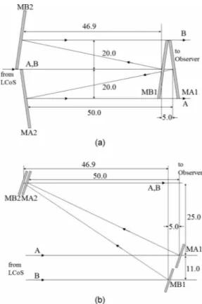
In order to increase the viewing window, the beam re-configuration method was applied by the proposed mirror module. The mirror module could reconfigure the diffracted beam shape by the SLM. The schematic of the mirror mod-ule is shown in Fig.2, and a photograph is shown in Fig.3. This module consists of four mirrors, of which two mirrors are held in the upper side, and the others are held in the lower side. The diffracted light on the LCoS is reflected on the lower mirrors, MA1 and MB1, and reflected again on the upper mirrors, MA2 and MB2. In more detail, the lower
Object point ) , , (xp yp zp ξ η
z
O p r ) 0 , , ( ηξ Reference beam ξ θ η θ HologramFig. 1 Model to calculate the Fresnel hologram.
Fig. 2 Schematic of the mirror module to reconfigure the SLM:共a兲
mirrors operate to divide the resolution in vertical direction, and the upper mirrors operate to rearrange the divided SLM in the horizontal direction to reconfigure the wide SLM in the horizontal direction. For example, the lower mirror MA1 reflected the diffraction light to the upper mirror MA2. On the other hand, MB1 reflected the diffraction light to MB2. Using the mirror module, the resolution of the reconfigured SLM has double resolution in the horizon-tal direction. Inversely, the vertical resolution is decreased. 3.2 Pixel Reconfiguration
The shape of the reconfigured SLM is different from that of the real SLM. Therefore, the computer-generated hologram 共CGH兲 should be generated as to the reconfigured SLM. Then, the generated hologram should be rearranged to match the real SLM. Its conceptual diagram is shown in Fig.4. At first, the resolution of the used SLM is divided into small vertical segments, and then these are rearranged in the horizontal. The digital hologram for the wide holo-graphic display system is generated on the redefined reso-lution.. According to this method, it could be made the wide and high resolution SLM in horizontal. Although the resolution is decreased in the vertical direction, the ob-server can get a 3-D effect from the hologram, because humans get more 3-D information in the horizontal direc-tion.
4 Benefit of Hologram Viewing Window
In this section, we consider the efficiencies of the hologram viewing window and diffraction according to the proposed method. In addition, the method was compared with the conventional method, which uses only one SLM.
4.1 Diffraction Angle
An LCoS is utilized to display the hologram as an SLM. The maximum diffraction angle of the hologram depends on the pixel pitch of the SLM used. The relation between the output angle, out, and the illumination angle, ill, is
shown in Fig.5, and is determined by8
2p= sinout− sinill, 共5兲
where is wavelength of the laser, and p is pixel pitch of the LCoS. The maximum diffraction angle max is
ex-pressed as
max=out−ill, 共6兲
and ifill= 0,
max=out= sin−1
2p. 共7兲
4.2 Conventional Method
As an LCoS is utilized as the SLM in the holographic dis-play system, the hologram viewing window can be ex-pressed as
Vh= Wh+ 2D tand, 共8兲
Vv= Wv+ 2D tand, 共9兲
where Vh and Vv are the horizontal and vertical viewing
window sizes, respectively; Whand Wvare the LCoS sizes
in the horizontal and vertical, respectively; D is the dis-tance from the LCoS to viewpoint, anddis the diffraction
angle of the LCoS. For example, if the pixel pitch is 9.5m and the wavelength is 633 nm, the maximum dif-fraction angledis 1.90 deg. Accordingly, the viewing
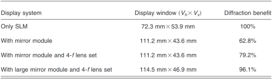
win-dow at 500 mm from the LCoS, whose resolution is 4096 ⫻2160 pixels, is about 72 mm⫻54 mm. This viewing window size will be used as the basis of comparison as to the benefit. The simulation environment is shown Table1.
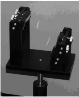
Fig. 3 Photograph of part of the novel optical system.
Fig. 4 Optimizing pixel configuration.
4.3 With Mirror Module
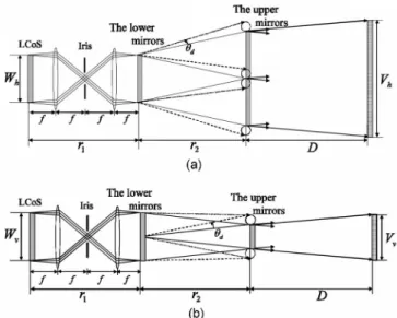
The schematic of the SLM reconfiguration method using only the proposed mirror module is shown in Fig.6. This figure shows how the diffracted light on the SLM is passed by the mirror module and its diffraction characteristics. In this analysis, the distance, r1and r2, between the SLM and mirrors is 50 mm, and the viewing distance is 500 mm from upper mirrors to observer. Therefore, it was assumed that the mirror size is the same as the segment size, which is the SLM divided logically in vertical direction.
First, the diffracted light on the SLM, whose size is 38.9 mm⫻20.5 mm, is reflected by the lower mirrors. The size of the diffraction window on the lower mirrors is 42.3 mm⫻23.9 mm. However, since the mirror size is smaller than that of the diffraction window, only the part whose size is the same as the SLM is reflected by the lower mirrors. Then, its diffraction benefit is 79.2%.
Second, the light reflected by the lower mirrors is re-flected again by the upper mirrors. The diffraction window on the upper mirrors is also 42.3 mm⫻23.9 mm, because the light propagates to its diffracted direction. The diffrac-tion benefit as to the upper mirrors is 79.2%. Accordingly, the total diffraction benefit is 62.8%, and the hologram dis-play window to the observer is 111.2 mm⫻43.6 mm, an increase of 124.6%. The display window is increased 1.5
times in the horizontal direction and decreased 0.8 times in the vertical direction. Although the total display window is increased, this method is not suitable to be observed, be-cause the total diffraction benefit is not enough.
4.4 With Mirror Module and 4-f Lens System
If the SLM and the mirror module are just used in the display system to reconfigure the diffracted light on the SLM, this method could not have satisfactory diffraction benefit, as mentioned in the previous section. Therefore, a 4-f lens system is involved to improve the diffraction ben-efit of the proposed method. The schematic as to the mirror module with the 4-f lens set is shown in Fig. 7. The 4-f lens set is placed between the LCoS and the lower mirrors. The diffracted light on the SLM is passed through the two lenses, the 4-f lens set, and they are imaged on the lower mirrors. This means that the SLM is moved at the position of the lower mirrors, and the incident light on each segment on the SLM is diffracted and propagated for each upper mirror. Accordingly, the diffraction benefit could be in-creased because the loss of diffracted light on the mirrors occurs only on the upper mirrors. The display window by means of this method is 111.2 mm⫻43.6 mm. Although this size is the same with the previous method, the diffrac-tion benefit, 79.2%, is increased as result.
A mirror, whose size is larger than the divided segment size of the SLM, can be utilized in the mirror module to cover the whole diffracted light on the SLM. Then, the loss of the diffracted light occurs only on the adjoining part of the upper mirrors. Therefore, the diffraction benefit could be increased up to 96.1%. Its display window is also 111.2 mm⫻43.6 mm. The display window and diffraction benefit according to each method are shown in Table2. As show in Table2, these could be achieved to display a ho-logram in a wide observable window using a large mirror module and 4-f lens set.
Table 1 Simulation environment.
SLM resolution 4096⫻2160 pixels Resolution of reconfigured SLM 8192⫻1080 pixels
SLM pixel pitch 9.5m
Light wavelength 633 nm
Viewing distance 500 mm
Fig. 6 Diffracted light on the LCoS and reflected light on the mirror
corresponding to the using only mirror model:共a兲 top view, 共b兲 side view.
Fig. 7 Diffracted light on the LCoS and reflected light on the mirror
corresponding to the using mirror model and 4-f lens system:共a兲 top view,共b兲 side view.
4.5 Noise and Interval Effect Due to the Folding Mirror
4.5.1 Noise on reconstruction
In this manuscript, the basic idea is partition of a fringe pattern on SLM optically and reconfiguration of the seg-mented fringe pattern on a display plane to achieve a wide holographic display. However, the reconstructed image from the reformed fringe pattern by the SLM reconfigura-tion method with only mirror module has some noise. This noise is caused by the mismatched diffracted light, which is reflected on the opposite mirror. As shown in Fig.6, some parts of the diffracted light on the lower side and upper side on the SLM are propagated to the opposite mirror in the lower mirror set. In addition, some parts of the reflected light on the lower mirror set are propagated to the opposite mirror in the upper mirror set. Therefore, some diffracted light corresponding to the left side on the display plane is propagated to the right side on the display plane, and some diffracted light corresponding to the right side is propa-gated to the left side. This mismatched light makes noise on the display plane. This noise is the overlapped reconstruc-tion, which consists of the expected reconstruction and re-flected reconstruction from the opposite mirror. This noise can be removed by the 4-f lens system. A fringe pattern on the SLM is imaged on the lower mirror set by means of the 4-f lens system. Therefore, the diffracted light from each fringe pattern corresponding to the left side and right side on the display plane is propagated to the accurate direction without any overlapping light. As shown in Fig. 7, the fringe pattern is imaged on the lower mirror set. Even if some part of the reflected light by the lower mirror set is propagated to the opposite mirror in the upper mirror set, as
shown in Fig.7共a兲, this reflected light is propagated to out-side the available viewing zone. Therefore, the noise, the overlapped image with the left side image and right side image, does not occur in the viewing zone.
4.5.2 Interval in mirror set
The mirror module is used in the proposed method. As mentioned earlier, the mirror module consists of four mir-rors, two mirrors for the lower mirror set and the other two mirrors for the upper mirror set. In each mirror set, two mirrors are separated and have a narrow interval due to the folding mirror. This interval may cause fringe loss. If this method is utilized for a 2-D image display, image loss will cause a serious problem. However, in the case of the holo-gram, diffracted light from a whole fringe pattern makes a single reconstruction on a space. On the other hand, the contribution corresponding to a single point is from the whole fringe area. Therefore, even if some information is lost by the interval in the mirror set, the reconstruction does not get any distortion or noise.
5 Experiment and Result
In this experiment, an LCoS is used to display the holo-gram. A cube, shown in Fig.8, is employed as the model to generate the hologram because it is easy to notice the view-ing direction. The generated hologram, calculated by Eq.
共1兲to Eq.共4兲, is displayed three ways: using only the SLM, with the mirror module, and with the large mirror module
Table 3 Characteristics of the optical holographic display system.
LCoS Resolution 4096⫻2160 pixels Pixel pitch 9.5m Refresh rate 62.5 Hz
Grayscale level 8 bits
Optical setup Wavelength 633 nm Focal length of lens set 300 mm Laser power 25 mW Viewing distance 500 mm
Fig. 8 Perspective image.
Table 2 Characteristics of the optical holographic display system.
Display system Display window共Vh⫻Vv兲 Diffraction benefit
Only SLM 72.3 mm⫻53.9 mm 100%
With mirror module 111.2 mm⫻43.6 mm 62.8%
With mirror module and 4-f lens set 111.2 mm⫻43.6 mm 79.2% With large mirror module and 4-f lens set 114.5 mm⫻46.9 mm 96.1%
including the 4-f lens set. The characteristics of the display system are described in Table3. The schematic of the op-tical holographic display system with the mirror module and 4-f lens set is shown in Fig.9. In Fig.9, the laser beam is expanded by the spatial filter to match to the shape of the
LCoS. Then, the beam is collimated with the lens, L3. The beam is reflected by the half-silvered mirror and illuminates the LCoS. The incident beam is diffracted on the LCoS and imaged on the lower mirrors of the mirror module through the 4-f lens set. Last, the reconfigured beam by means of the mirror module forms a reconstructed image in the air.
Using the mirror module, the measured width of the viewing window in the SLM reconfiguration method with 4-f lens system is 110 mm, almost the same as the theoret-ical value of 111.2 mm. Even if the 4-f lens system is not utilized, this method also has the same viewing window width of 110 mm. However, as mentioned in Sec. 4.5, some noise occurs on the display plane. Therefore, by means of the mirror module and the 4-f lens system, a wide viewing window without noise caused by the mismatched diffracted light could be achieved.
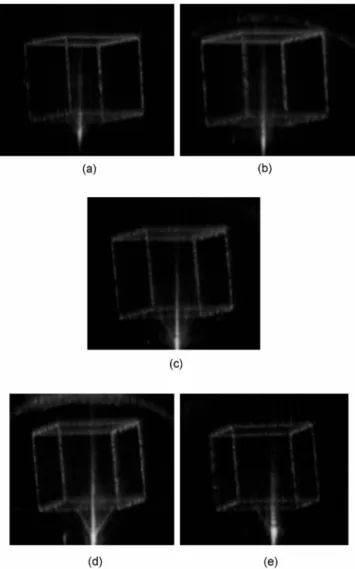
The reconstructed images by the optical system with the mirror module and 4-f lens set are shown in Fig. 10. In addition, the performance of the designed method is shown in Table 4. In Fig. 10, one can notice that the proposed method gives a clear reconstructed image in a wide viewing zone. In addition, if the viewpoint is moved from center to the right side or left side, the observer could recognize the motion parallax. Consequently, through the proposed method, an observer could see the displayed holographic image in the wide viewing window and be able to get 3-D effects in the displayed holographic image.
6 Conclusion
In this paper, we presented a novel holographic display method to enlarge the viewing window of a hologram viewing zone. A beam reconfiguration method by means of a mirror module has been designed. Additionally, an optical holographic display system was built with the mirror mod-ule, and the reconstructed images displayed in wide view-ing window were shown. As a result, the designed method showed that a digital hologram can be displayed in a wide viewing window whose size is 114.5 mm⫻46.9 mm. Acknowledgments
This research was supported by the Ministry of Knowledge Economy共MKE兲 of Korea under the Information Technol-ogy Research Center共ITRC兲. Support Program supervised by the Institute of Information Technology Assessment 共IITA兲; IITA-2008-C1090-0801-0018.
Table 4 Performance of the proposed method.
Reconfigured resolution 8192⫻1080 pixels Diffraction benefit 96.1%
Display window共Vh⫻Vv兲 114.5 mm⫻46.9 mm Diffraction angle 1.90 deg
Mirror size 43 mm⫻14 mm
Viewing distance 500 mm
Fig. 10 Reconstructed images by the optical system with the mirror
module and 4-f lens set:共a兲 −50 mm from center, 共b兲 −25 mm from center,共c兲 0 mm from center, 共d兲 25 mm from center, and 共e兲 50 mm from center. M L3 L1 Iris L2 HM LCoS Laser Spatial Filter Mirror Module f f f f M L3 L1 Iris L2 HM LCoS Laser Spatial Filter Mirror Module f f f f
Fig. 9 Schematic of the holographic display system for beam
References
1. P. St. Hilaire, S. A. Benton, M. Lucente, M. L. Jepsen, J. Kollin, H. Yoshikawa, and J. Underkoffler, “Electronic display system for com-putational holography,” in Practical Holography IV, S. A. Benton, Ed.,Proc. SPIE1212, 174–182共1990兲.
2. F. Mok, J. Diep, H. Liu, and D. Psaltis, “Real-time computer gener-ated hologram by means of liquid-crystal television spatial light modulator,”Opt. Lett.11共11兲, 748–750 共1986兲.
3. P. St. Hilaire, S. A. Benton, M. Lucente, J. D. Sutter, and W. J. Plesniak, “Advances in holographic video,” in Practical Holography VII,Proc. SPIE1914, 188–196共1993兲.
4. K. Maeno, N. Fukaya, O. Nishikawa, K. Sato, and T. Honda, “Electro-holographic display using 15M pixels LCD,” in Practical Holography IX, S. A. Benton, Ed.,Proc. SPIE2652, 15–22共1996兲.
5. Y. Hayashi and Y. Takaki, “Horizontal resolution enhanced hologram to increase horizontal viewing angle,” in Practical Holography XXII, Proc. SPIE6912, 69120I共2008兲.
6. N. Ohmura, H. Kang, T. Yamaguchi, and H. Yoshikawa, “A method to increase the hologram viewing angle by the beam reconfiguration,” in Practical Holography XXII,Proc. SPIE6912, 69120O共2008兲.
7. J. Hahn, H. Kim, Y. Lim, G. Park, and B. Lee, “Wide viewing angle dynamic holographic stereogram with a curved array of spatial light modulators,”Opt. Express16共16兲, 12372–12386 共2008兲.
8. E. Hecht, Optics, Wesley Longman, New York共2002兲.
Hoonjong Kang graduated from
Kwang-woon University with a bachelor of engi-neering degree in 1998. He joined the 3D Korea company in 2000, received a master of engineering degree from Kwangwoon University in 2001, and joined the govern-ment institute ETRI in 2002. He received a doctor of engineering degree from Nihon University in 2008 and joined the European FP7 Real3D project in 2008. His research interests include computer-generated holo-grams, electroholography, 3-D display, and signal processing of ste-reoscopic images.
Naoyuki Omura received BS and MS
de-grees in electrical engineering from Nihon University in 2006 and 2008, respectively. His current research interests are in the ar-eas of electroholography and computer-generated holograms.
Takeshi Yamaguchi received BS and MS
degrees in electronic engineering from Ni-hon University in 2004 and 2006, respec-tively. Since 2006, he has been on the fac-ulty at Nihon University. His current research interests are in electroholography and computer-generated holograms.
Hiroshi Yoshikawa received a BS degree,
an MS degree, and a PhD from Nihon Uni-versity, all in electrical engineering, in 1981, 1983, and 1985, respectively. He joined the faculty at Nihon University in 1985, where he currently holds the position of professor of electronics and computer science. From 1988 to 1990, he was a research affiliate of MIT Media Laboratory. His current research interests are in electroholography, computer-generated holograms, display ho-lography, and computer graphics.
Seung-Cheol Kim received his BS degree
from Kwangwoon University, Seoul, Korea, in 2002 and his MS and PhD degrees in electronic engineering from the Graduate School of Kwangwoon University in 2004 and 2007, respectively. Since 2007, he has been a research professor at the 3D Display Research Center of Kwangwoon University. His research interests include 3-D imaging and display, holography, and optical infor-mation processing.
Eun-Soo Kim joined the faculty of
Kwang-woon University in 1981, where he is pres-ently a professor at the Department of Elec-tronic Engineering. He was a visiting professor in the Department of Electrical Engineering, CalTech. In 2000, his research laboratory was honored as a National Re-search Laboratory by the Ministry of Sci-ence and Technology of Korea, and his 3DRC共3D Display Research Center兲 was also honored as an outstanding ITRC 共Infor-mation Technology Research Center兲 by the Ministry of Communi-cation and Information of Korea in 2003. He is currently the acting president of the 3D Fusion Industry Consortium and the president-elect of the Korean Information and Communications Society. He established the International Workshop on 3D Information Technol-ogy in 2004, and he co-organized the International 3D Fair in col-laboration with the 3D Consortium of Japan in 2006. His research interests include 3-D imaging and displays, 3-D fusion technologies, and their applications.