296 OPTICS LETTERS / Vol. 18, No. 4 / February 15, 1993
Multistage optical interconnection architectures with the
least possible growth of system size
Haldun M. Ozaktas
Department of Electrical Engineering, Bilkent University, 06533 Bilkent, Ankara, Turkey
David Mendlovic
Faculty of Engineering, Tel-Aviv University, 69978 Tel-Aviv, Israel
Received September 22, 1992
Multistage interconnection architectures can provide an arbitrary pattern of one-to-one connections between N input and N output channels. We show that bitonic multistage architectures, such as the Banyan architecture, result in the fundamentally least possible growth of system size with increasing N.
In this Letter we are concerned with optical intercon-nection architectures that can provide an arbitrary pattern of one-to-one connections between N input channels and N output channels. We assume that the input and output channels are arrayed in a regu-lar Cartesian manner at the input and output planes, respectively. It is desirable to pack the channels as densely as possible and also to make the distance between the input and output planes as small as possible. This is important not only because of the desirability of a compact system but also because of the need to reduce the latency between the inputs
and outputs. We require that our interconnection architecture have the flexibility of being able to be customized such that any arbitrary one-to-one con-nection pattern between N input and N output chan-nels can be realized. There are N! such patterns. For special connection patterns exhibiting some form of locality or regularity, smaller system sizes than to be derived in this Letter may be possible.'
From a fundamental viewpoint, a cross-sectional area of -A2 is needed per independent spatial channel for diffraction-limited systems,2 so that the cross-sectional area of the system should be at least
NA2, implying a transverse linear extent of -N"12A (A
is the wavelength of light). Indeed, a conventional space invariant imaging system with an f-number f- - 1 can handle -N pixels in this cross-sectional area. However, such systems cannot be used to implement an arbitrary pattern of connections. If we could arbitrarily manufacture waveguides of effec-tive cross-sectional area -A2 in a three-dimensional (3-D) block of material then we could clearly wire up
any given pattern of connections. '2 According to 3-D
very-large-scale integrated complexity theory, which is also applicable to waveguides, the linear extent of such a system could approach the fundamental limit -N"/2A.3 Unfortunately, the realization of such a system is currently hypothetical.
Arbitrary connection patterns are possible with the general class of multifacet architectures.4-'0 However, this class of architecture results in both transverse and axial linear extents of -NA, which
is much larger than the fundamental limit oc N"2A."2 Although such systems may be useful for smaller values of N, they are clearly not desirable for larger values of N."
It is possible to realize an arbitrary pattern of con-nections within a cube of linear extent only approxi-mately an order of magnitude greater than the fun-damental limit by using the architecture described in Ref. 12; however the manufacture of this system may pose certain practical difficulties that make it unattractive. Also, this architecture provides con-nections between a set of processors arrayed in a 3-D grid, whereas in some applications it is desired to provide connections between two-dimensional (2-D) input and output planes.
Multistage interconnections networks seem to offer the best solution.10"1-'3 Such systems employ
oclog2 N stages. Each stage consists of a global yet regular pattern of connections, with only a small degree of space variance,'0 so that the transverse linear extent is close to -N"/2A. The stages are cascaded by an array of exchange-bypass modules. Such modules may be passive couplers
for a fixed interconnection network (which may
be realized by modifying the holographic telescope array described in Ref. 14), or they may be active switches for a dynamic network. We concentrate on fixed networks, remembering that the extension to dynamic networks is straightforward if suitable switches are available.
In the following we show that certain types of mul-tistage architecture are superior to others, since they result in the fundamentally least possible growth rate of system size as a function of N, as opposed to others, which result in a system size that is worse than the fundamental limit by a factor depending on N.
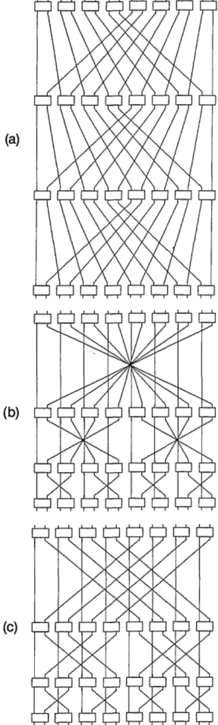
Several alternative topologies and optical imple-mentations have been suggested for multistage in-terconnection networks.""-5 '8 Figure 1 shows the perfect shuffle, crossover, and Banyan networks. All three are topologically equivalent, as can be shown by appropriately rearranging the nodes in the intermedi-ate stages.'9 Two Banyan networks, pasted back to 0146-9592/93/040296-03$5.00/0 © 1993 Optical Society of America
February 15, 1993 / Vol. 18, No. 4 / OPTICS LETTERS
(a)
(b)
(c)X
Fig. 1. (a) Perfect shuffle, (b) crossover, and (c) Banyan networks with 16 inputs and outputs; (c) is drawn such that the slopes of the slanted connections are equal.
back, allow an arbitrary permutation to be realized by appropriately setting the exchange-bypass modules.3 In our context, this means that any arbitrary pat-tern of one-to-one connections can be implemented. It is important to note that the number of input channels N that can be permuted is half the number of inputs N' of the Banyan shown in Fig. 1, which can permute N = 8 channels although it has N' = 16 inputs. Thus every other input of the Banyan is not connected to anything. Because all three networks are equivalent, the same is possible with the perfect shuffle or crossover, a fact that has been exploited.'5' 20 In passing, we also note that by using a greater number of stages, the perfect shuffle shown in the figure can also be used to permute 16 input channels.
The perfect shuffle has received the most attention in the optical community. Each stage of the perfect shuffle being identical, the resulting system linear ex-tent is mclog2 N times the axial extent of a single stage. Thus, the size and latency of a perfect-shuffle-based multistage system are worse than the fundamental limit by a factor that increases with N. This may not be important for telecommunications systems in which the throughput is the relevant parameter and latency is not an important consideration. However, in computing systems, minimization of latency (signal delay) may be of importance as it is directly related to the performance of the system.
The Banyan, crossover, and other bitonic networks have the property that the axial extent of each suc-cessive stage is half that of the previous one, so that the total length of the system is proportional to 1 + 1/2 + 1/4 + ... =2, representing a consider-able improvement over the logarithmic factor for the perfect-shuffle-based system.
It is possible to implement the one-dimensional (1-D) Banyan shown in Fig. 1 in three dimensions, however, the 2-D Banyan, which is a straightforward extension of the 1-D Banyan, is more natural for a 3-D implementation. The connection pattern can be deduced by analogy with the 1-D case.
Optical implementations of the Banyan have been suggested."6 Figure 2 shows an implementation based on the general partially space-variant system studied in Ref. 10. This may not be the most practical implementation but is most suited for the purpose of this Letter because of its conceptual simplicity, which permits easy derivation of the resulting transverse and axial linear extent. What is shown in Fig. 2 is essentially a 4f system, which has been compacted so that it is only 2f long. Connections must be made in nine different directions in the 2-D Banyan network [as opposed to three different directions in Fig. 1(c)], so that the filter (Fourier) plane must be split into a 3 X 3 array of nine facets. In other words, the degree of space variances of the system is nine. All connections made in the same direction can use the same facet in the filter plane. Filter selection is made through selection prisms in the input plane. In Ref. 10, where this architecture is extensively discussed, it is shown that if the pupil is split into M facets, the number of connections possible is SW/M, where SW denotes the space-bandwidth product.
KJ
f
LX/{U
f
Fig. 2. Side view of the general partially space-variant system used to derive the transverse and axial extent of the optical implementation of the Banyan network. The system looks the same from the top.
298 OPTICS LETTERS / Vol. 18, No. 4 / February 15, 1993 Remember that in order to handle N input channels, the 1-D Banyan network required N' =
2N connections per stage. In direct analogy, the 2-D Banyan will require N' = 4N connections per stage. If we assume that the system is diffraction limited, its space-bandwidth product is given by SW = L,2/(f"A)2, where L4 is the transverse linear extent of the system. Thus with M = 9 facets, N' = SW/9, and L4 is given by
L4 = SW'I2f#A = 3NY1/2f#A = 6f#N1/2A (1)
Referring to Figs. 1 and 2, it can be seen that the diameters and focal lengths of the lenses needed for each consecutive stage are half those of the previous stage, since each consecutive stage need handle only a fourth of the number of pixels that was handled by the previous stage. Thus, since 1 + 1/2 + ... =2, the total axial extent La of the multistage system is only twice that of the length of the first stage, which is given by 2f = 2f #Lt. Thus
La = 2 X 2f = 24f#NlI 2A. (2) For an f# - 1 system, we see that L4 is 6 times worse, and La is 24 times worse, than the fundamental limit
(which could be achieved, for instance, if we could
manufacture the hypothetical waveguides discussed above and route them with 100% efficiency).
In conclusion, it is desirable to be able to imple-ment an arbitrary pattern of connections and make efficient use of the space-bandwidth product of the system at the same time. Multistage networks make this possible, with only a small space-bandwidth product inefficiency. The price that must be paid is that oclog2N stages are necessary. However, as we have shown, multistage networks based on bitonic patterns, such as the Banyan and crossover (as op-posed to the perfect shuffle), result in an axial linear extent that does not have a logarithmic dependence on N. We have shown that the transverse and axial extents of such a system are worse than the fun-damental minimum by -6 and -24, respectively, independent of N. Thus the fundamental limit can be achieved in terms of growth rate.
It may be pointed out that the constant factor of 24 is rather large, which is true. However, if a nonbitonic network were used, such as the perfect shuffle, the axial linear extent would be proportional to the logarithmic factor log2 N. Noting that, for
instance for N = (1024)2, we have log2N = 20, it is clear that use of a bitonic network is preferable in comparison.
Although we do not expect that they can be brought close to unity, it may be possible to improve the constants further.
Part of this research was done while the authors were visiting the University of Erlangen-N-Urnberg, Erlangen, Germany. The authors thank Adolf W. Lohmann for discussions and suggestions. David Mendlovic acknowledges a MINERVA fellowship, and Haldun M. Ozaktas acknowledges an Alexander von Humboldt Foundation fellowship.
References
1. H. M. Ozaktas, Y. Amitai, and J. W. Goodman, Opt.
Commun. 82, 225 (1991).
2. H. M. Ozaktas and J. W. Goodman, J. Opt. Soc. Am. A
7, 2100 (1990).
3. A. L. Rosenberg, J. Comput. Mach. 30, 397 (1983). 4. S. K. Case, P. R. Haugen, and 0. J. L0berge, Appl.
Opt. 20, 2670 (1981).
5. R. K. Kostuk, J. W. Goodman, and L. Hesselink, Appl. Opt. 24, 2851 (1985).
6. R. Kostuk, J. W. Goodman, and L. Hesselink, Appl. Opt. 26, 3947 (1987).
7. M. R. Feldman, C. C. Guest, T. J. Drabik, and S. C.
Esener, Appl. Opt. 28, 3820 (1989).
8. M. R. Feldman and C. C. Guest Appl. Opt. 28, 3134
(1989).
9. G. E. Lohman and A. W. Lohmann, Opt. Eng. 27, 893
(1988).
10. G. E. Lohman and K.-H. Brenner, Optik 89, 123
(1992).
11. D. Mendlovic and H. M. Ozaktas, "Optical coordinate transformation methods and optical interconnection architectures-analogy and comparison," submitted to Appl. Opt.
12. H. M. Ozaktas, Y. Amitai, and J. W. Goodman, Opt.
Commun. 85, 1 (1991).
13. A. W. Lohmann, Appl. Opt. 25, 1543 (1986).
14. A. W. Lohmann and F. Sauer, Appl. Opt. 27, 3003
(1988).
15. J. Jahns and M. J. Murdocca, Appl. Opt. 27, 3155
(1988).
16. J. Jahns, Opt. Commun. 76, 321 (1990).
17. A. W. Lohmann, W. Stork, and G. Stucke, Appl. Opt.
25, 1530 (1986).
18. K.-H. Brenner and A. Huang, Appl. Opt. 27, 135
(1988).
19. N. Streibl, K.-H. Brenner, A. Huang, J. Jahns,
J. Jewell, A. W. Lohmann, D. A. B. Miller, M.
Murdocca, M. E. Prise, and T. Sizer, Proc. IEEE 77,
1954 (1989).
20. D. S. Wise, in VLSI Systems and Computations, H. T. Kung, B. Sproull, and G. Steele, eds. (Computer Science Press, Rockville, Md., 1981), pp. 186-195.