Journal of Instrumentation
OPEN ACCESS
The CMS Phase-1 pixel detector upgrade
To cite this article: W. Adam et al 2021 JINST 16 P020272021 JINST 16 P02027
Published by IOP Publishing for Sissa Medialab
Received: July 23, 2020 Accepted: December 22, 2020 Published: February 22, 2021
The CMS Phase-1 pixel detector upgrade
The Tracker Group of the CMS collaboration
E-mail: [email protected]
Abstract: The CMS detector at the CERN LHC features a silicon pixel detector as its innermost subdetector. The original CMS pixel detector has been replaced with an upgraded pixel system (CMS Phase-1 pixel detector) in the extended year-end technical stop of the LHC in 2016/2017. The upgraded CMS pixel detector is designed to cope with the higher instantaneous luminosities that have been achieved by the LHC after the upgrades to the accelerator during the first long shutdown in 2013–2014. Compared to the original pixel detector, the upgraded detector has a better tracking performance and lower mass with four barrel layers and three endcap disks on each side to provide hit coverage up to an absolute value of pseudorapidity of 2.5. This paper describes the design and construction of the CMS Phase-1 pixel detector as well as its performance from commissioning to early operation in collision data-taking.
Keywords: Instrumentation for particle accelerators and storage rings - high energy (linear accel-erators, synchrotrons); Particle tracking detectors; Detector design and construction technologies and materials; Detector alignment and calibration methods (lasers, sources, particle-beams)
In memory of Gino Bolla, the physicist, the friend. ∗ 25 September 1968. † 4 September 2016.
2021 JINST 16 P02027
Contents
1 Introduction 1
2 Design of the CMS Phase-1 pixel detector 2
3 Silicon sensor modules 6
3.1 Sensors 7
3.2 Readout chip 9
3.3 Token bit manager 13
3.4 BPIX module construction 15
3.5 FPIX module construction 17
3.6 Module qualification and grading 17
4 Mechanics 24
4.1 BPIX mechanics 24
4.2 FPIX mechanics 29
5 Readout architecture and data acquisition system 32
6 Power system 35
6.1 DC-DC converters 36
6.2 Low voltage power distribution 37
6.3 Cables and power supplies 39
6.4 Issues with DC-DC converters during 2017 operation 40
7 Cooling 40
7.1 Cooling concept 41
7.2 Cooling requirements 41
7.3 Cooling system 42
7.4 Detector thermal mockup 43
7.5 Cooling system performance and operation 43
8 Pilot system 44
9 Integration, testing, and installation 45
9.1 Integration of the BPIX detector 45
9.2 Integration of the FPIX detector 48
2021 JINST 16 P02027
10 Detector calibration 53
10.1 Adjustment of programming phase 54
10.2 Adjustment of POH laser bias current 54
10.3 TBM delay adjustment 55
10.4 Threshold adjustment and noise measurement 55
10.5 Pixel pulse height calibration 56
11 Operation and performance 57
11.1 Detector working fraction 57
11.2 Detector time and space alignment with first collisions 58
11.3 SEU recovery mechanisms during operation 59
11.4 Detector response and performance monitoring 59
11.4.1 Charge measurement 59
11.4.2 Lorentz angle 60
11.4.3 Detector hit efficiency 61
11.4.4 Position resolution 62
12 Summary 63
13 Glossary of special terms and acronyms 64
The Tracker Group of the CMS collaboration 70
1 Introduction
The CMS experiment [1] at the CERN Large Hadron Collider (LHC) includes a silicon pixel detector
as the innermost part of the tracking system. The pixel detector provides 3-dimensional space points in the region closest to the interaction point that allow for high-precision, charged-particle tracking
and for vertex reconstruction [2,3]. The pixel detector is located in a particularly harsh radiation
environment characterized by a high track density. The original pixel detector [1] consisted of three
barrel layers at radii of 44, 73, and 102 mm and two endcap disks on each end at distances of 345 and 465 mm from the interaction point. It was designed for a maximum instantaneous luminosity of
1 × 1034 cm−2s−1and a maximum average pileup (number of inelastic interactions per bunch
cross-ing) of 25 in LHC operation with 25 ns bunch spacing. With the upgrade of the accelerators during the first long shutdown (LS1, 2013–2014), these parameters have been exceeded and the luminosity and pileup have more than doubled compared to the design values. In order to maintain efficient and robust tracking at CMS under these conditions, the original pixel detector has been replaced by a
new system, referred to as the CMS Phase-1 pixel detector [4]. The installation of the CMS Phase-1
pixel detector took place during the extended year-end technical stop of the LHC in 2016/2017.1
1The LHC year-end technical stop in 2016/2017 was extended by two months and lasted from December 2016 to April 2017.
2021 JINST 16 P02027
The CMS Phase-1 pixel detector constitutes an evolutionary upgrade, keeping the well-tested key features of the original detector and improving the performance toward higher rate capability, improved radiation tolerance, and more robust tracking. It is expected to deliver high-quality data until the end of LHC Run 3 (currently expected for 2024), after which the whole CMS tracker
detector will be replaced in preparation of the High-Luminosity LHC [5].
In this paper, the design and construction of the CMS Phase-1 pixel detector are described and its performance from commissioning to early operation in collision data-taking is presented. Issues experienced during the first data-taking period are discussed and improvements and modifications that have been implemented during the 2017/2018 LHC year-end technical stop, or will be imple-mented during the second long shutdown (LS2, 2019–2021), are explained. The outline of the paper is as follows. The overall system aspects, main design parameters, and performance goals are
described in section2. The design, assembly, and qualification of the detector modules is discussed
in section3. Sections4,5,6, and7discuss the detector mechanics, readout electronics and data
acquisition system, as well as the power system and cooling. In section8the commissioning of a
pilot system is reviewed and in section9the integration, testing, and installation of the final detector
system is described. Results from detector calibration and operations are discussed in section10
and11. A summary and conclusions are presented in section12. A glossary of special terms and
acronyms is given in section13.
2 Design of the CMS Phase-1 pixel detector
The layout of the CMS Phase-1 pixel detector is optimized to have four-hit coverage over the
pseudorapidity range |𝜂| < 2.5,2improved pattern recognition and track reconstruction, and added
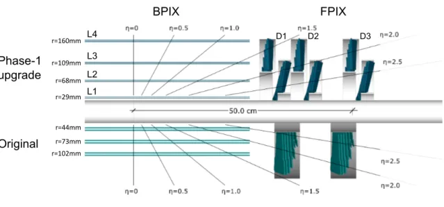
redundancy to cope with hit losses. During LS1, a new beam pipe with a smaller radius of 23 mm, compared to a radius of 30 mm of the original beam pipe, was installed in CMS. This allowed for placement of the innermost layer of the CMS Phase-1 pixel detector closer to the interaction point compared to the original pixel detector. The CMS Phase-1 pixel detector consists of four concentric barrel layers (L1-L4) at radii of 29, 68, 109, and 160 mm, and three disks (D1-D3) on each end at distances of 291, 396, and 516 mm from the center of the detector. The layout of the CMS Phase-1
pixel detector is compared to the one of the original pixel detector in figure1. The total silicon
area of the CMS Phase-1 pixel detector is 1.9 m2, while the total silicon area of the original pixel
detector was 1.1 m2.
The CMS Phase-1 pixel detector is built from 1856 segmented silicon sensor modules, where 1184 modules are used in the barrel pixel detector (BPIX) and 672 modules are used for the forward disks (FPIX). Each module consists of a sensor with 160 × 416 pixels connected to 16 readout chips (ROCs). In total there are 124 million readout channels. The design of the detector modules is
discussed in more detail in section3.
The main dimensional parameters of the CMS Phase-1 pixel detector are reviewed in table1.
The BPIX and FPIX detectors are independent components, both mechanically and electrically. The
BPIX detector consists of two half-barrels (figure2) with a total length of 540 mm, each divided
2CMS uses a right-handed coordinate system. The 𝑥-axis points to the center of the LHC ring, the 𝑦-axis points up vertically and the 𝑧-axis points along the beam direction. The azimuthal angle 𝜙 is measured in the 𝑥𝑦-plane and the radial coordinate is denoted by 𝑟. The polar angle 𝜃 is defined in the 𝑟 𝑧-plane and the pseudorapidity is 𝜂 = − ln tan(𝜃
2021 JINST 16 P02027
into four layers (called half-shells). Similarly the FPIX detector is assembled from twelve half-disks (six half-disks on each side) with a radial coverage from 45 to 161 mm. The half-disks are further divided into inner and outer half-rings supporting 22 and 34 modules, respectively. The division of the detector into mechanically independent halves makes it possible to install the pixel detector inside the CMS detector with the beam pipe in place. This scheme allowed the CMS Phase-1 pixel detector to be installed within the limited period of time during the 2016/2017 LHC extended year-end technical stop. Furthermore, it permits access to the detector for maintenance work and refurbishment also during the short periods of regular LHC year-end technical stops.
Table 1. Summary of average r, 𝑧 positions and number of modules for the four BPIX layers and the six FPIX rings.
BPIX
Layer Radius [ mm ] 𝑧position [ mm ] Number of modules
L1 29 −270 to +270 96
L2 68 −270 to +270 224
L3 109 −270 to +270 352
L4 160 −270 to +270 512
FPIX
Disk Radius [ mm ] 𝑧position [ mm ] Number of modules
D1 inner ring 45–110 ±338 88 D1 outer ring 96–161 ±309 136 D2 inner ring 45–110 ±413 88 D2 outer ring 96–161 ±384 136 D3 inner ring 45–110 ±508 88 D3 outer ring 96–161 ±479 136
The BPIX and FPIX detectors are each supplied by four service half-cylinders that hold the readout and control circuits and guide the power lines and cooling tubes of the detector, as shown in
figure2. The BPIX detector is divided into two mechanically independent halves, both composed of
one half detector and two service half-cylinders. The FPIX detector is divided into four mechanically independent quadrants, each formed by three half-disks installed in a service half-cylinder.
The CMS Phase-1 pixel detector is required to fit into the same mechanical envelope as the original system and to partly reuse existing services. This has put strong constraints on the design of the new system. In particular, higher bandwidth electronics are needed to transmit the increased data volume from the CMS Phase-1 pixel detector through the existing optical fibers to the data acquisition (DAQ) system. Since the CMS Phase-1 pixel detector has 1.9 times more channels than the original pixel detector, the power consumption increases accordingly. The CMS Phase-1 pixel detector uses DC-DC power converters to supply the necessary current to the modules while reusing the existing cables from the power supply racks to the tracker detector patch panel inside the CMS
2021 JINST 16 P02027
Phase-1 upgrade Original BPIX FPIX D1 D2 D3 L1 L2 L3 L4 r=29mm r=68mm r=109mm r=160mm r=102mm r=73mm r=44mmFigure 1. Layout of the CMS Phase-1 pixel detector compared to the original detector layout, in longitudinal view.
Figure 2. Drawing of the Phase-1 BPIX and FPIX detectors together with the service half-cylinders that hold the readout and control circuits as well as power and cooling lines.
magnet bore. Sections5and6give more information about the readout and power systems of the
CMS Phase-1 pixel detector.
In order to optimize the tracking and vertexing resolution, it is crucial to minimize the material used in the detector. Despite the additional sensor layers, the material budget of the CMS Phase-1 pixel detector in the central region is almost unchanged compared to the original detector, while
2021 JINST 16 P02027
2 − −1 0 1 2 η 0 0.1 0.2 0.3 0.4 0.5 0.6 0.7 0.8 0x/X Phase-1 pixel detector
Support Sensitive Cables Cooling Electronics Air
Original pixel detector
CMS Simulation 2 − −1 0 1 2 η 0 0.05 0.1 0.15 0.2 0.25 0 λ
x/ Phase-1 pixel detector
Support Sensitive Cables Cooling Electronics Air
Original pixel detector
CMS Simulation
Figure 3. Material budget in units of (left) radiation lengths, 𝑋0, and (right) hadronic interaction lengths,
𝜆0, as a function of pseudorapidity, 𝜂, as obtained from simulation. The material budget of the original pixel detector is compared to the CMS Phase-1 pixel detector within the tracking acceptance. The material budget of the CMS Phase-1 pixel detector is split into the contributions of the different categories. The peaks in the distribution in the forward region reflect the disk structure. The largest values for radiation length and hadronic interaction length lie outside the tracking acceptance at around |𝜂| = 3.5 and amount to 1.9 x/X0
and 0.36 x/𝜆0, respectively.
it is significantly reduced in the forward region at |𝜂| > 1. This is achieved by using advanced carbon-fiber materials for the mechanical structure and adopting the use of a lower mass, two-phase
CO2cooling system. Furthermore, the electronic boards on the service half-cylinders are placed
in higher pseudorapidity regions, outside of the tracking acceptance. Figure3shows the material
budget of the CMS Phase-1 pixel detector compared to the original pixel detector within the tracking acceptance in terms of radiation lengths and hadronic interaction lengths. The material budget is
obtained from GEANT4-based simulation models [6] of the CMS pixel detectors.
With the innermost layer placed at a radius of 29 mm from the beam, the modules in this
region have to withstand very high radiation doses and hit rates, as shown in table2. A hadron
fluence of 3.6 × 10¹⁵neq/cm2(fluence measured in units of 1 MeV neutron equivalents) is expected
to be accumulated in the innermost layer after collecting an integrated luminosity of 500 fb−1. This
fluence is about twice as high as the operational limits of the proposed system, as defined by the
charge collection efficiency of the sensor [4]. Therefore, the innermost BPIX layer will be replaced
during LS2. The fluence in the second layer of the BPIX detector is about four times less, and hence the outer BPIX layers will stay operational during the entire period. The same is true for the modules in the FPIX detector.
The expected hit rates in the outer BPIX layers and the FPIX detector are two to three times
higher compared to the original detector and increase to almost 600 MHz/cm2 for BPIX L1. The
ability of the CMS Phase-1 pixel detector to cope with these hit rates is achieved by the design of
new ROCs, as discussed in section3.2. Because of these improvements, the CMS Phase-1 pixel
detector has the same, or even better, performance compared to the original detector at twice the
2021 JINST 16 P02027
Table 2. Expected hit rate, fluence, and radiation dose for the BPIX layers and FPIX rings [7]. The hit rate cor-responds to an instantaneous luminosity of 2.0 × 1034 cm−2s−1[4]. The fluence and radiation dose are shown for integrated luminosities of 300 fb−1for BPIX L1 and 500 fb−1for the other BPIX layers and FPIX disks.
Pixel hit rate Fluence Dose
[MHz/cm2] [1015n eq/cm2] [Mrad] BPIX L1 580 2.2 100 BPIX L2 120 0.9 47 BPIX L3 58 0.4 22 BPIX L4 32 0.3 13
FPIX inner rings 56–260 0.4–2.0 21–106
FPIX outer rings 30–75 0.3–0.5 13–28
3 Silicon sensor modules
The CMS Phase-1 pixel detector uses a similar module design as the BPIX modules of the original
detector. A pixel detector module is built from a planar silicon sensor with a size of 18.6 × 66.6 mm2
(active area of 16.2 × 64.8 mm2), bump-bonded to an array of 2 × 8 ROCs. Each ROC is segmented
into 4160 readout channels and reads out the pulse height information for each pixel. The standard
pixel size is 100 × 150 μm2(as in the original pixel detector). Since two ROCs can only be placed
at some minimum distance from each other, pixels along the ROC boundaries have twice the area and those at the corners have four times the area of a standard pixel. On the other side of the silicon sensor, a high-density interconnect (HDI) flex printed circuit is glued and wire-bonded to the ROCs. A token bit manager chip (TBM) controls the readout of a group of ROCs and is mounted on top of the HDI (two TBMs in the case of L1 modules). In order to simplify module production and maintenance, the same rectangular module geometry is used for the BPIX and FPIX detectors.
Drawings of the CMS Phase-1 pixel detector modules are shown in figure4.
In the BPIX detector, the orientation of the sensor surface of the modules is parallel to the magnetic field, as in the original pixel detector. The pixels are oriented with the long side parallel
to the beam line. In the FPIX detector, the modules in the outer rings are rotated by 20◦ in a
BPIX L1 BPIX L2-L4 FPIX
Figure 4. Drawings of the pixel detector modules for BPIX L1 (left), BPIX L2–4 (middle), and the FPIX detector (right).
2021 JINST 16 P02027
turbine-like geometry, similar to the original detector. However, to obtain optimal resolution in both the azimuthal and radial directions for the inner ring, the modules in the inner ring are arranged
in an inverted cone array tilted by 12◦with respect to the beam line, combined with the 20◦rotation
(also shown in figures1and20). The sensor orientation in the FPIX detector is such that the long
side of the pixel is in the radial direction, and thus different with respect to the original detector.
3.1 Sensors
The sensor design of the original pixel detector was the result of an extensive R&D program
described in ref. [8]. Studies with irradiated sensors have continued and have shown that the
sensors also fulfill the requirements of the CMS Phase-1 pixel detector [9].
The sensors of the BPIX and FPIX detectors were produced by different companies in order not to depend on a single source. The BPIX sensors were produced by CiS Forschungsinstitut für Mikrosensorik in Erfurt, Germany, while the FPIX sensors were manufactured by SINTEF Micro-systems and Sensors in Oslo, Norway. To achieve optimal yield, the sensor concept and design was tailored to each vendor’s production process, which led to two quite different sensor types.
Both types of sensors are made of silicon and follow the n-in-n approach [8], with strongly
n-doped (n+) pixelated implants on an n-doped silicon bulk and a p-doped back side. In a reverse-bias
configuration, the n+implants collect electrons. This is advantageous since the electrons have a
higher mobility compared to holes and therefore are less affected by charge trapping caused by
radia-tion damage in the silicon after high irradiaradia-tion [10,11]. This leads to a high signal charge even after
a high fluence of charged particles. After irradiation-induced space charge sign inversion, the highest electric field in the sensor is located close to the n-electrodes used to collect the charge, which is also advantageous as it allows the sensors to be operated under-depleted. A further consequence of the higher mobility of the electrons is the larger Lorentz drift of the signal charges. This drift leads to in-creased charge sharing between neighboring pixels and is exploited to improve the spatial resolution. In n-in-n sensors, the junction that depletes the sensitive volume is realized as a large-area implant on the back side of the sensor. In order to guarantee a controlled termination of the junction towards the edge of the device, a series of guard rings are implemented, meaning that both sides of the sensor need photolithographic steps. The guard-ring scheme allows all sensor edges to be at ground potential, which greatly simplifies the construction of detector modules, because no high-voltage protection is needed to adjacent components like ROCs or neighboring modules.
The interface between the silicon substrate and the silicon oxide carries a slight positive charge which increases by orders of magnitudes after ionizing radiation. This causes a conducting electron accumulation layer, which may short the electrocollecting electrodes. Therefore an n-side isolation is required. The technical implementation of this isolation has a large impact on the pixel cell layout and was chosen to best match the techniques offered by the two vendors.
In the case of the BPIX sensors, the n-side isolation was implemented through the moderated
p-spray technique [12] with a punch-through biasing grid. The moderated p-spray technique allows
for small distances between the pixel implants. Such a layout leads to a homogeneous electric field inside the sensor. The small gaps between pixel implants also facilitate the implementation of punch-through bias structures, the bias dots. The bias dots provide a highly resistive connection to each pixel. This can be used to apply bias voltage to the sensor prior to any further assembly. This in turn
2021 JINST 16 P02027
bump contact via aluminum n−implant p−stop p−stop openingFigure 5. Photograph of four pixel cells on a BPIX sensor (left) and schematic of two pixel cells on an FPIX sensor (right).
allows sensor quality assurance measurements prior to bump bonding, such as the current-voltage
(IV) characteristic. A photograph of four pixel cells in a BPIX sensor is shown in figure5(left).
The BPIX sensors were produced on approximately 285 μm thick phosphorous-doped 4-inch wafers from silicon mono-crystals produced in the float-zone (FZ) process. The resistivity of 3.7 kΩ cm leads to an initial full depletion voltage of 55 V. The crystal orientation is h111i. The first
processing step is an oxidation according to the recommendation of the ROSE collaboration [10]
(Diffusion Oxygenated FZ material). All BPIX sensors were processed using silicon originating from the same ingot. Therefore, the variations of the full depletion voltage are small.
Three sensors were placed on each 4-inch wafer. A wafer was accepted when at least two of the sensors fulfilled the specifications. Most critical was the requirement of a maximum current of
2 μA at 150 V reverse bias voltage, measured at a temperature of +17◦C.
The FPIX sensors use open p-stops for n-side isolation. Each pixel is surrounded by an
individual p-stop which has an opening on one side, as shown in figure5(right). In between the
p-stops, electrons will accumulate close to the surface and form a resistive grid covering the whole sensor. The resistance of the grid depends strongly on the back side voltage. The openings connect each pixel to this grid providing the same functionality as the bias dots in the BPIX layout. Owing to the presence of the p-stops, the distance between the charge-collecting pixel electrodes is larger compared to the BPIX sensors, which leads to a smaller capacitance. The disadvantage, a less homogeneous drift field, is of less importance in the forward region as the charge sharing between pixels is caused by the geometric tilt of the modules and not by the magnetic field.
The FPIX sensors have been produced on 300 μm thick 6-inch FZ-wafers with h100i-orientation. Eight sensors were placed on one wafer. A wafer was accepted if at least six of
the sensors fulfilled the specifications [13,14].
By design, the position resolution of the CMS Phase-1 pixel detector depends strongly on the
charge sharing between pixels. The pixel shape of 100 × 150 μm2 means that in order to obtain
an optimal position measurement in the azimuthal direction (the bending plane for charged particle
tracks within the CMS magnet) the charge width3has to be of the order of the pixel pitch, that is
3The charge width is defined as the projection on the module coordinates of the area where the charge is collected on the detector surface.
2021 JINST 16 P02027
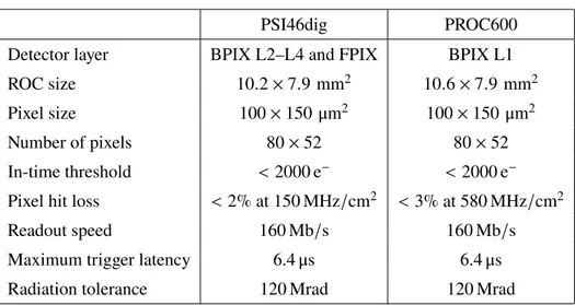
Table 3. Parameters and design requirements for PSI46dig and PROC600.
PSI46dig PROC600
Detector layer BPIX L2–L4 and FPIX BPIX L1
ROC size 10.2 × 7.9 mm2 10.6 × 7.9 mm2
Pixel size 100 × 150 μm2 100 × 150 μm2
Number of pixels 80 × 52 80 × 52
In-time threshold <2000 e− <2000 e−
Pixel hit loss <2% at 150 MHz/cm2 <3% at 580 MHz/cm2
Readout speed 160 Mb/s 160 Mb/s
Maximum trigger latency 6.4 μs 6.4 μs
Radiation tolerance 120 Mrad 120 Mrad
100 μm. In the strong magnetic field of 3.8 T provided by the CMS magnet, the Lorentz angle
(LA) for the drifting electrons has a value of about 27◦. With the sensor thickness of 285 μm, this
produces a charge width of 145 μm, which is sufficient to share the charge between at least two pixels. The LA depends strongly on the bias voltage of the sensor and weakly on the temperature. It is also affected by the radiation damage in the sensor. This means that in order to obtain the
optimal position resolution the LA has to be regularly monitored (section11.4.2).
The durability of the modules is, to a large extent, defined by the possibility of increasing the sensor bias voltage to obtain a sufficiently high signal charge. During operation in CMS, modules in the innermost layer of the CMS Phase-1 pixel detector have been run with high efficiency at a bias
voltage of 450 V up to an integrated luminosity of almost 120 fb−1. After the replacement of the
innermost BPIX layer during LS2, the new innermost layer must withstand a fluence that is expected to be about twice as high until the end of Run 3. In order to maintain a high enough signal charge, the pixel detector power supplies have been upgraded to deliver a maximum voltage of 800 V during LS2.
3.2 Readout chip
The upgraded ROCs used in the CMS Phase-1 pixel detector (PSI46dig [15], PROC600 [16]) are
manufactured in the same 250 nm CMOS technology as the ROC used in the original pixel detector
(PSI46 [17]). The design requirements for PSI46dig and PROC600 are summarized in table3.
The PSI46dig is used in the outer BPIX layers (L2–4) and in the FPIX detector. It maintains the well-tested and reliable core of the original ROC and its readout architecture based on the
column-drain mechanism [18].
The pixel matrix of the PSI46dig consists of an array of pixel unit cells (PUC) arranged in 26 double columns of 2×80 pixels each, which are controlled by the double-column periphery. The double columns, the double-column periphery, and the chip periphery are the three main functional units of a ROC. They fulfill the task of recording the position and charge of all hit pixels with a time resolution of 25 ns, and store the information on-chip during the Level-1 trigger latency of the CMS experiment (currently 4.15 μs). The behavior of the PSI46dig is controlled by means of 19
digital-2021 JINST 16 P02027
to-analog converter (DAC) registers which can be programmed using a 40 MHz serial bus. The design of the pixel matrix for the PSI46dig remains essentially unchanged compared to the PSI46, except for the implementation of an improved charge discriminator. The main modifications made in the chip periphery are to overcome the limitations of the PSI46 at high rate. The ROCs need two different power supplies, namely +2.5 V and +1.5 V. These supply the digital and analog circuits, respectively, through internal linear voltage regulators. The power consumption of the PSI46dig is about 41 mW for the analog part. The power consumption of the digital part has a static contribution
of 70 mW and a dynamic contribution that amounts to about 31 mW per 100 MHz/cm2hit rate.
The PUC can receive a signal either through a charge deposition in the sensor or by injecting a calibration signal. Within the PUC, the signal is passed through a two-stage pre-amplifier and shaper system to a comparator, where zero-suppression is applied. The comparator threshold is set by a DAC for the whole ROC, but can be adjusted via a 4-bit DAC (trim bits) for each pixel individually. Furthermore, the comparator of a pixel can be disabled by setting a mask bit. If a signal exceeds the comparator threshold the analog pulse-height information is stored, the corresponding pixel becomes insensitive, and the column periphery is notified. The column periphery writes the value of the bunch crossing counter into a time-stamp buffer and issues a readout token. A column-drain mechanism is initialized to read out the pixel hit information. Hit pixels send the registered analog pulse-height information together with the pixel address to the column periphery for storage in the data buffers, before being set again into data taking mode. The communication between the PUC and the periphery allows for three pending column drains, meaning that the double columns are capable of recording new hits while still copying information from the previous hits to the buffers in the periphery. Upon arrival of the Level-1 trigger-accept (L1A) signal, the double-column periphery verifies the pixel hit information by comparing the time stamp with a counter delayed with respect to the bunch crossing counter by the trigger latency. In case of agreement the double column is set into readout mode and is not ready to accept any new data, otherwise the data in the corresponding buffer are discarded. When a readout token issued by the TBM arrives at the double-column periphery the validated data are sent to the chip periphery and the double column is reset.
The main changes for the PSI46dig compared to the PSI46 include the increase of the size of the data (from 32 to 80) and time-stamp (from 12 to 24) buffers to store the hit information during the trig-ger latency, the implementation of an additional readout buffer stage to reduce dead time during the column readout, and the adoption of 160 Mb/s digital readout. The readout speed of the ROC itself is unchanged, but the transition from 40 MHz analog coded data to 160 Mb/s digital data allows faster readout of the modules. Consequently an 8-bit successive approximation analog-to-digital converter (ADC) running at 80 MHz has been implemented in the PSI46dig. Digitized data are stored in a 64 × 23 bit first-in-first-out register, which is read out serially at 160 MHz. A phase-locked loop (PLL) circuit has been added to derive the 80 and 160 MHz clock frequencies from the LHC clock. The improvements in the design of the charge discriminator reduce cross talk between pixels
and time walk of the signal [17] and thus lead to lower threshold operation (below 1500 e−with noise
less than 100 e−in a module). Time walk is caused by the fact that the rise time of the amplified
signal cannot be infinitely fast. Therefore, signals with different amplitudes cross the threshold at different times, with the low amplitude signals crossing the threshold later than the high amplitude signals. Also the decision speed of the comparator increases for small signals just slightly above the threshold. If the low amplitude signals are delayed beyond the 25 ns time window between LHC
2021 JINST 16 P02027
Figure 6. Measured and simulated efficiencies for PSI46 (used in the original pixel detector) and PSI46dig (used in the CMS Phase-1 pixel detector in the outer BPIX layers and the FPIX detector) as a function of X-ray hit rates [21].
collisions, they will appear in the next bunch crossing and will be lost for hit reconstruction. The threshold needed for the signal charge to be recorded in the correct bunch crossing is higher than the pixel threshold, and is referred to as “in-time” threshold. The effect of the time walk on the
threshold was reduced significantly, from about 1000 e−in PSI46 to about 300 e−in PSI46dig.
Furthermore, higher radiation tolerance is achieved. The radiation tolerance of the PSI46dig has been tested after irradiation to up to 150 Mrad using a 23 MeV proton beam at ZAG Zyklotron AG in Karlsruhe, Germany. The PSI46dig shows excellent performance, and threshold and noise
characteristics remain basically unchanged after irradiation [19]. In addition, comprehensive test
beam studies have been conducted to verify the design and to quantify the performance of detector
assemblies with the new ROCs in terms of tracking efficiency and spatial resolution [20]. Leakage
currents from sensors will increase significantly after irradiation and the pixel input circuit has to be able to absorb it. There is no dedicated circuitry for current compensation in the pixels, however currents up to 50 nA/pixel, can be absorbed, after feedback adjustments, without any observable gain changes. At 100 nA/pixel there is only a small (about 10%) gain degradation.
The single-pixel hit efficiency at high rates has been measured using the internal calibration
signal while exposing the ROC to high-rate X-rays [21]. The efficiency has been measured for pixel
hit rates up to 300 MHz/cm2and was found to be in excellent agreement with expectations based on
detailed architecture simulations, as shown in figure6. Based on the same architecture simulation
but now using simulated proton-proton collision events, the data losses in the FPIX detector and in
the outer BPIX layers are less than 2% at the expected maximum hit rate of 120 MHz/cm2. The
PSI46dig fulfills all the design requirements for the outer BPIX layers and the FPIX detector and has performed very well during the proton-proton collision data-taking in 2017 and 2018.
The PROC600 has been designed for the innermost layer, where hit rates of up to almost
600 MHz/cm2are expected. The main design requirements for the PROC600 are faster hit transfer
from pixels to the periphery as well as dead-time free buffer management. This has been achieved by a complete redesign of the double column unit. In the PROC600, the pixels within a double column
2021 JINST 16 P02027
are dynamically grouped into clusters of four and read out simultaneously to enable faster readout. Reading groups of four pixels in one step avoids the need for each hit pixel to initiate its readout sequence by the periphery. This approach speeds up the readout process significantly even if some pixels, out of the group of four, are read out despite having no hit. The readout is zero-suppressed in order to remove pixels in the clusters without measured signal amplitude. Furthermore, a new checkout mechanism has been implemented that allows the column-drain mechanism to run continuously and that does not require a buffer reset. An improved communication logic design between the PUC and the periphery allows for seven pending column drains in the PROC600, compared to three pending column drains in the PSI46dig. The power consumption of the analog part of the PROC600 is the same as for the PSI46dig. The static digital power is 90 mW with an
increase of 20 mW per 100 MHz/cm2hit rate.
The radiation tolerance of the PROC600 has been tested under proton irradiation with doses
up to 480 Mrad [16]. The PROC600 remained fully operational after irradiation to a dose of
120 Mrad, which is larger than the total dose expected during its operation in the innermost BPIX layer (accounting for the replacement of BPIX L1). Even at doses of up to 480 Mrad only a slight degradation in the performance was observed. Furthermore, the high-rate performance of the PROC600 has been studied in laboratory tests with X-rays as well as in a 200 MeV high-rate proton
beam at the PSI Proton Irradiation Facility [16].
The PROC600 has delivered high-quality physics data during operation in 2017 and 2018. Two shortcomings of the PROC600 have been noticed during data-taking. One is a higher-than-expected noise at high hit rates because of cross talk between pixels. The second is a lower-than-expected efficiency, also at high hit rates, because of a rare loss of data synchronization in double columns. Both problems were mitigated by operational procedures, avoiding any compromise in the data quality. Nevertheless, a revised design of the PROC600, to be used in the replacement of the innermost BPIX layer in Run 3, has been developed. The higher-than-expected noise was traced to an inappropriate shielding of the circuitry for calibration pulse injection connected to the pre-amplifier input node. This issue has been addressed in the revised version. In addition, the routing and shielding of power and address lines was improved. Both changes lead to lower noise and lower cross talk between pixels.
The main change in the revised version of the PROC600 addresses the rare events of data synchronization loss in the double columns. The issue has been tracked to a timing error in the time-stamp buffer of the double column, which leads to inefficiencies at low and high hit rates. When the time-stamp buffer is full, the double column no longer acquires new hits until the content of the buffer cell with the oldest hit information is cleared. If a coincidence of a return to acquisition mode and a new hit in a pixel occurs, it can generate a spurious column drain and thus loss of synchro-nization of the double column such that subsequent hits are not assigned to the correct event. Since the time stamp buffer is filled more frequently when the occupancy is high, the effect of the spurious signal affects the efficiency when running at high luminosity. At low rates, a very specific sequence of events generates a wrong time-stamp buffer-full signal. This in itself would not be a problem, but in combination with the issue of spurious column drains described above can again lead to a loss of synchronization. In both cases synchronization is restored by sending a reset signal to the double column. During operation, reset signals were sent at a frequency of 70 Hz to mitigate the
2021 JINST 16 P02027
Figure 7. Measured single-pixel hit efficiency for the PROC600 as a function of pixel hit rate in the 200 MeV proton beam at PSI. The version of the PROC600 used in the CMS experiment in operation in 2017 and 2018 is compared to the revised version of the chip that will be used in the replacement of BPIX L1 in Run 3. The yellow and green points labeled “with resets” correspond to the data-taking mode in which every trigger signal was preceded by a reset signal.
of the revised PROC600. The high-rate performance of the revised version of the PROC600 has been studied by measuring the single-pixel hit efficiency during operation in the high-rate proton
beam at the PSI Proton Irradiation Facility. The result is shown in figure7. The revised version
of the PROC600 maintains a single-pixel hit efficiency above 95% at rates up to 600 MHz/cm2.
Furthermore, the time-walk behavior has been optimized by adjusting the speed of the comparator.
3.3 Token bit manager
The main functionality of the TBM is to synchronize the module data transmission. The TBM issues
a readout token upon arrival of an L1A signal from the CMS back-end trigger electronics [23]. The
token is passed to each ROC in turn and the readout is initialized. The last ROC in the chain sends the token back to the TBM. The TBM multiplexes the signals from the ROCs, adds a header and a trailer to the data stream, and drives the signal through the readout link. Before issuing the next readout token, the TBM awaits the return of the previous token. Trigger signals that arrive during the readout of a previous event are placed on a stack (up to 32 trigger signals).
The TBMs for the CMS Phase-1 pixel detector are a digital evolution of the respective analog
chip used in the original CMS pixel detector [24]. To increase the data bandwidth sent from a
module, two 160 Mb/s ROC signal paths, with one path inverted, are multiplexed into a 320 Mb/s signal, then encoded into a 4-bit/5-bit Non-Return to Zero Inverted (NRZI) 400 Mb/s data stream.
2021 JINST 16 P02027
This is suitable for use in transmitting the data optically to the downstream DAQ system. By adopting a digital readout at 400 Mb/s and using four links per module in BPIX L1, the readout bandwidth is increased by a factor of four compared to the original innermost layer with two analog links at 40 MHz. The digital TBM has single output (TBM08) and dual output (TBM09, TBM10) versions, which are used in different parts of the detector. TBM09 and TBM10 models differ only in the delay between the trigger and when tokens are sent to initiate ROC readout. The TBM08 version has two independent 160 Mb/s ROC readout paths, and the TBM09 and TBM10 versions have four separate, semi-independent, 160 Mb/s ROC readout paths. The headers and trailers corresponding to the two 160 Mb/s ROC readout paths that share a 400 Mb/s readout link are sent synchronously. The time when one of the 160 Mb/s readout paths in TBM09 and TBM10 is idle is filled with digital zeros.
Each TBM has a 5-bit hub address. The address is defined by the voltage levels applied to the corresponding pads on the TBM. The pads are either connected through wire bonds to the HDI or to internal pull-down resistors. The hub address is used to uniquely identify each module served by a given control link to send the configuration information to the correct TBM for subsequent loading into the ROCs. In the BPIX detector, up to 28 modules are served by the same control link, while in the FPIX detector 14 modules share a common link.
In addition to the increased output bandwidth, several features were added to the TBMs for the CMS Phase-1 pixel detector. A token timeout was added that resets the ROCs and drains buffered data of the triggered events on the stack if a token does not return within an adjustable amount of time. The adjustment is 6.4 μs times an 8-bit setting and can be disabled. The setting used during operation corresponded to 147 μs, making sure that very long readouts did not block the DAQ system. The functionality of issuing an automatic reset was added in order to send periodic ROC resets every 𝑁 triggers, where 𝑁 is a multiple of 256 times an 8-bit setting. However, this functionality has not been used. Instead it was decided that the periodic reset signals are issued centrally, by the CMS trigger control and distribution system (TCDS), to recover from the loss of synchronization of the PROC600. The periodic reset signals are sent after 3000 bunch crossings without L1A signals in order to drain the data from the ROC buffers and avoid losing the data. As a result of adopting a digital readout, delay adjustments could be added for the ROC readouts, the token outputs, the data headers and the data trailers. Relative phase adjustments between the 40 MHz incoming clock, the 160 MHz clock and the 400 MHz clock were also added. The size of the data header was increased to allow additional TBM status information to be transmitted (currently an unused feature). The size of the data trailer was increased to indicate whether a token timeout and/or automatic reset occurred and to transmit the number of buffered trigger signals on the stack waiting to be processed. Operation of the TBM during collision data taking revealed a vulnerability to single-event upsets (SEUs). SEUs are interactions in which a highly ionizing particle deposits a significant amount of energy in silicon that affects the functioning of a transistor and changes its state. The transistor design can be modified to make it more robust, however the effect cannot be completely eliminated. Therefore, with some probability, every transistor in the readout chain of the pixel detector will be affected by SEUs. For the CMOS technology used in the design of the ROC and TBM chips the SEU
probability was measured using pion beams and was found to be 2.4 × 10⁻¹⁴ cm2per storage cell for
unprotected transistors and 2.6 × 10⁻¹⁶ cm2per storage cell for protected transistors [17]. Because
of a design issue in the TBM, a single transistor in the circuit responsible for event synchronization is not protected against SEUs and cannot be reset by a reset signal. Whenever it is blocked, the
2021 JINST 16 P02027
Table 4. Overview of module types used in the CMS Phase-1 pixel detector.
ROC Number of TBM Number of Number of 400 Mb/s
ROCs TBMs readout links per module
BPIX L1 PROC600 16 TBM10 2 4
BPIX L2 PSI46dig 16 TBM09 1 2
BPIX L3, L4 & FPIX PSI46dig 16 TBM08 1 1
readout chain is interrupted and can only be recovered by a power cycle. This means that parts of the pixel detector have to be periodically power-cycled. Since the flux of particles is highest in the region closest to the interaction point, BPIX L1 is most affected by this issue. The observed fraction of TBM cores (two cores per TBM) which would be blocked without intervention in BPIX L1 is
about 0.7% per 100 pb−1of integrated luminosity, which translates into an overall inefficiency of
about 0.2%. For the outer layers the flux of charged particles is significantly lower compared to L1 and therefore SEU effects in the TBMs are much reduced.
An additional iteration of the TBM chips was designed in the spring of 2018 to address the TBM SEU issue and to add an adjustable delay of up to 32 ns to the 40 MHz clock. The delay was added
to allow finer adjustment of the relative timing between modules (section11.2). The new chips will
be used in new modules in BPIX L1 that will be incorporated during the consolidation work in LS2.
3.4 BPIX module construction
The 1184 BPIX modules installed in the detector all have the same geometry, but three module designs were needed to meet the requirements of the different layers. BPIX L3 and L4 modules have an identical design, based on the PSI46dig ROC and the TBM08, with one readout link per module. The BPIX L2 modules also feature the PSI46dig ROC, but use a TBM09 chip that has two readout links to match the higher data volume at smaller radii. The hit rates in BPIX L1 requires not only two TBM10 chips with a total of four readout links, but also the PROC600, different cables, and, because of severe space constraints, a different mounting scheme. The different module types
are summarized in table4(and displayed in figure4).
The production of the BPIX modules was shared by five consortia, including institutions from Germany, Switzerland, Italy, Finland, and Taiwan, in five different module-assembly centers. ROCs and TBMs were probed on wafers before dicing. The yield was 93% for ROCs and 53% for
TBMs.4 While the assembly tools and procedures were mostly standardized [25], each center used
different bump-bonding techniques. Two module-assembly centers worked with industrial vendors
for the bump bonding (IZM [26,27] for INFN and ADVACAM [28] for CERN/National Taiwan
University/University of Helsinki). Bump bonding for the Swiss institutions was done in cooperation
with Dectris [29], based on the indium process developed at PSI [30]. The KIT/RWTH Aachen
consortium developed a cost-effective combination of an in-house flip-chip step at KIT with SnPb
bumps deposited on ROC wafers by RTI [31–33]. The DESY/University of Hamburg production
4A batch of TBMs produced for the new L1 of BPIX was found to have a yield close to 90% after a new wafer probe cleaning method was used before probing.
2021 JINST 16 P02027
Figure 8. Cross section of a pixel detector module for BPIX L2–4 cut along the short side of the module.
was done completely in-house except for the under-bump metallization (UBM) of sensors. The
sensor UBM consists of electroless nickel plating by PacTech [34, 35], which is also used in
the KIT process. Solder balls were placed sequentially with a laser-assisted solder-sphere jetting
technique, at a rate of 6–8 balls per second [35]. The quality of the bump bonding was in each case
verified as soon as the bump-bonded assemblies (’bare modules’) were produced, or received by the module-assembly center. Thereby, single ROCs were contacted individually with a probe-card while supplying bias voltage to the sensor. This was performed to verify the functionality of ROCs and TBMs, to measure the leakage current of the sensor, and to check the quality of the bump-bonding process. The replacement of single ROCs that failed in an otherwise good module was practiced by four of the five centers, and about 10–20% of the modules were reworked. The total bump-bonding yield, including rework, varied from center to center, and ranged between 84 and 96%.
To turn the bare module into a full module, a thin four-layer HDI was glued onto the back of the sensor and wire-bonded to the ROCs. The gluing stations were operated manually with alignment pins guaranteeing sufficient mounting precision. TBMs had already been mounted, wired-bonded and tested on the HDI before joining the HDI and the bare module. In contrast to the original pixel detector modules, the upgraded modules feature a detachable cable. A temporary short cable stayed connected during module assembly and testing and was only replaced by the long final cable for mounting on the detector mechanics.
BPIX L2–4 modules are mounted using base strips, that were glued under the ROCs on the
two long sides of the module (figure4, center). Silicon nitride was chosen as the material for the
base strips, as it is an insulator with a similar coefficient of thermal expansion as silicon. The base strips have extensions with holes for mounting screws that match the mounting points on the BPIX
mechanics. A drawing of the cross section of a detector module for BPIX L2–4 is shown in figure8.
The tight space requirements in the innermost BPIX layer required a different scheme with clamps
between two modules (figure4, left).
The last assembly step, after the successful completion of all quality assurance tests, was the mounting of a protection cap made from a 75 μm thick polyimide foil. The cap protects the wire bonds of ROCs and TBMs against mechanical damage from the cables of other modules when mounted on the BPIX mechanics. A picture of a BPIX L2 module after assembly of the protection
cap is shown in figure9. A single L2 module, excluding the cable, has a mass of about 2.4 g and
2021 JINST 16 P02027
Figure 9. Picture of a BPIX L2 module after assembly of the protection cap. The amber-colored protection cap covers the wire bonds of ROCs and TBMs. In the picture, the flat polyimide flex cable used for module testing is connected to the module.
3.5 FPIX module construction
The 672 FPIX modules installed in the detector all have the same design and are instrumented
with PSI46dig ROCs and a TBM08 with one readout link per module (table 4). The FPIX
modules (figure4) use a different sensor, HDI and aluminum/polyimide flat flex cable and are not
interchangeable with BPIX modules.
The bump-bonding procedure relied on a more automated version (Datacon APM2200 bump bonder) of the process used by the vendor RTI for the original FPIX detector (FC150 bump
bonder) [36]. The yield for pre-production modules was 87% and therefore it was felt that no
bare-module testing was needed for the production. However, during early production a poor yield of 30% was seen. After disassembling and inspecting a malfunctioning module it was found that abrasive blade dicing debris was damaging ROCs. Though a visual inspection of ROCs prior to bump bonding helped to identify damaged ROCs, higher yields were recovered only when the photoresist mask was left in place during dicing as was done during the pre-production. After this change the yield improved to 85%. Because of the poor yield in the early production it was decided to perform testing of bare modules for the last two batches of bump-bonded modules. After failing modules had been reworked, the yield rose to above 90%.
The bare modules were sent from RTI to two FPIX module assembly and testing sites in the U.S.A. Surface mount components were soldered to the HDI, and a TBM08 chip was glued and wire-bonded to the HDI. The HDI was then glued and wire-bonded to the bare module. Modules
were assembled using an automated gantry (figure10) with 10 μm precision using a vacuum chuck
and pick and placement equipment. The vision system labeled in figure 10 used the fiducial
markers on the HDI and bare module to assemble parts with sufficient precision. The wire bonds were encapsulated with Dow Corning Sylgard 186 to protect against humidity and to mechanically support the wire bonds. The gantry used for the module assembly steps is software controlled for both the gluing and encapsulation steps, leading to high reproducibility.
3.6 Module qualification and grading
Modules have been tested in similar test setups in all production centers in Europe and the U.S.A. Up to four modules could be tested in parallel on each setup. The modules were connected via copper cables to adapter cards, which were in turn connected to a digital test board (DTB) via a SCSI cable. The DTB is a compact DAQ system and contains an FPGA and a NIOS processor. The module testing software was running on a PC, connected via USB to the DTB. Modules were
2021 JINST 16 P02027
Figure 10. A picture of the robotic gantry as used for the assembly of the FPIX modules. Labels indicate the main tools used for the assembly.
placed in a cold-box that provided the desired temperature and relative humidity (< 10%) during
testing. All modules were tested at two temperatures, once at +17◦C and twice at −20◦C, which
corresponds to the temperature range expected during operation. Additionally, each module was
exposed to ten thermal cycles between +17◦C and −20◦C in order to verify that thermal stress does
not create any damage in the module.
The testing procedure includes verification of the basic functionality of the module, the mea-surement of the efficiency of the pixel unit cells, and equalization and calibration of the pixel re-sponse. In addition to the functionality tests of ROCs and TBMs, the IV characteristic of each module was determined by measuring the leakage current as a function of the reverse bias voltage. Module
qualification was performed using the pXar testing framework [37]. After completion of the
mod-ule evaluation process, modmod-ules suitable for detector installation were selected based on predefined grading criteria. Details of the module grading criteria and production yield are discussed below.
At the beginning of the testing procedure all modules were tested for basic functionality and
initial parameters for the DAC settings were obtained. First, the VanaDAC setting, which regulates
the analog supply voltage of the amplifiers, was adjusted. It was checked that the ROC can be
programmed by changing the Vana DAC setting and verifying the corresponding change in the
analog current. The VanaDAC was then set such that each ROC drew the nominal analog current of
24 mA. In the next step, the delay settings for the readout of the ROCs and TBM(s) were adjusted by performing a scan over the available phase space. The delay settings were scanned for all TBM cores simultaneously and set within the center of the valid region. Then, the setting of the
comparator threshold (VthrComp) was adjusted by using the charge injection mechanism of the ROC.
The amplitude of the injected signal is controlled by the VcalDAC, and its time delay by the CalDel
2021 JINST 16 P02027
of pixels. The working point was chosen in the center of the valid range for CalDel and at a value
of the VthrCompthat is well above the noise level, where the hit detection efficiency is maximal.
In the following step, the functionality of every pixel was verified. Several internal calibration signals were sent to each pixel and its response was analyzed. If the number of signals sent to the pixel and the number of signals read out from the pixel was the same, the pixel was considered functional. At the same time, the address of the pixel was verified by comparing the address to which the internal calibration signal was sent with the decoded address. Finally, the functionality of the pixel mask mechanism was tested. Calibration signals were sent to masked pixels and it was verified that there was no response from the corresponding pixels.
The trimming procedure was then performed. This procedure aims to equalize the thresholds of all 4160 pixels within a ROC. While the global threshold can be adjusted per ROC, the individual
pixel thresholds are fine-tuned by the trim bits, whose range is set by the VtrimDAC. The trim bits
and VtrimDAC were iteratively adjusted to a target threshold, corresponding to 2000 e−for module
testing. Furthermore, the functionality of the trim bits was verified by sequentially enabling each bit and checking its effect on the pixel threshold distribution.
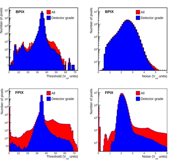
The threshold and noise after each iteration of the trimming procedure were determined by
measuring the S-curve [2]. The S-curve measures the hit detection efficiency as a function of the
amplitude of the injected calibration signal, adjusted by the Vcal DAC. It gets its name from the
shape of the error function used to fit the measured curve of efficiency vs. Vcalfor each pixel. The
value corresponding to a response efficiency of 50% determines the threshold, while the noise is proportional to the width of the error function. The threshold and noise distributions for BPIX and
FPIX modules that completed the evaluation process are shown in figure11. Besides determining
the average threshold and noise per ROC, the measurement was also used to flag noisy pixels. Some differences in the noise and threshold distributions of the BPIX and FPIX detector modules can be attributed to the different sensor technologies and the fact that the sensors are operated at different bias voltages. The tails at high values of the noise distributions are mostly due to the larger area pixels placed at the edges of the ROCs.
In the next step, the pulse height response was adjusted and calibrated. The appropriate dynamic range for the 8-bit ADC that digitizes the recorded pulse height is set by two DACs, called PHOffset and PHScale. PHOffset adds a constant offset to the pulse height measurement, while PHScale effectively sets the gain of the ADC. To use the ADC most effectively, the pulse height response is optimized by injecting signals with different charge amplitude. The calibration evaluates and records
the most probable value of the pulse height distribution as a function of the VcalDAC setting for
each pixel, as shown in figure12. These curves were fit with a linear function and the fit parameters
were stored for offline reconstruction of the hit position (discussed in section10.5). It is sufficient
to only consider the linear range of the distribution since it covers the range of charges most relevant
for the position measurement. Details about this calibration procedure can be found in ref. [2].
A test was then performed to check the quality of the bump bonding by identifying missing or bad connections. The test made use of a feature in the ROC that allows a calibration signal to be
sent to a top metal pad in the ROC [17]. The pad and the sensor are coupled capacitively through an
air gap. The generated signal was read out by the ROC, and in this way the pixel capacitance was measured. Any pixel that had a capacitance five standard deviations below the mean was flagged as faulty. The different bump-bonding technologies used at the various module production sites
2021 JINST 16 P02027
0 10 20 30 40 50 60 70 units) cal Threshold (V 1 10 2 10 3 10 4 10 5 10 6 10 7 10 Number of pixels All Detector grade BPIX 0 1 2 3 4 5 6 units) cal Noise (V 3 10 4 10 5 10 6 10 7 10 Number of pixels All Detector grade BPIX 0 10 20 30 40 50 60 70 units) cal Threshold (V 10 2 10 3 10 4 10 5 10 6 10 7 10 8 10 Number of pixels All Detector grade FPIX 0 1 2 3 4 5 6 units) cal Noise (V 3 10 4 10 5 10 6 10 7 10 Number of pixels All Detector grade FPIXFigure 11. Distribution of threshold (left) and noise (right) per pixel for all modules that completed the qualification process. The upper plots are for BPIX modules, the lower plots for FPIX modules. The module grading criteria are discussed in the main text.
generated differences in the bump heights, which strongly influenced the capacitive couplings. As a result the parameters of the bump-bonding test had to be adapted for each production site. The fraction of disconnected bumps varied between 0.01% and 0.05%, depending on the technology used. The average fraction of disconnected bumps was 0.025%, randomly distributed with some tendency to be higher at module corners.
The last step in the testing procedure was the measurement of the leakage current of the sensor as a function of the applied bias voltage. The IV characteristic of the modules was determined to assess whether the module was damaged by handling and to ensure that there was no intrinsic sensor defect that manifests itself only at low or high temperature.
All modules were tested with X-rays in order to measure the hit-detection efficiency at high
oc-cupancy and to calibrate the absolute energy response of every ROC [2]. First, each module was
ex-posed to a direct high-rate X-ray beam. The number of hits per pixel was recorded in several runs with
different hit rates ranging from 20 up to 160 MHz/cm2. For BPIX L1 modules the high-rate
2021 JINST 16 P02027
0 20 40 60 80 100 120 140 160 units) cal Injected charge (V 0 50 100 150 200 250Pulse height (ADC units)
Figure 12. Pulse height measured in one pixel as a function of amplitude of the internal calibration signal in units of Vcal. The slope of the curve below saturation is fitted with a linear function.
signal while exposing the module to high-rate X-rays to emulate the occupancy expected during
de-tector operation. As an example, the result of an X-ray test of a BPIX L2 module is shown in figure13.
To determine the absolute energy calibration of the module, tests with different X-ray energies were performed. Here, the direct X-rays illuminate different metallic foils (targets), which then produce monochromatic X-rays at a known energy depending on the material of the foil. Four different foil types were used: tin, zinc, molybdenum, and silver, and the pixel pulse height was measured for each target. The most probable value of each pulse height distribution (in units of
Vcal, according to the calibration described before) was calculated and plotted versus the expected
number of electrons produced by monochromatic X-rays (assuming 3.6 eV per electron-hole-pair),
as illustrated in figure 14. This gives the pulse height calibration in units of electrons. The
calibration varies by about 15% from pixel to pixel within a ROC as well as among ROCs. The
average charge calibration for PSI46dig was measured to have a slope of 47 ± 5 electrons per Vcal
unit and an offset of −60±130 electrons. For the PROC600 the average calibration was measured on a subset of modules to have a slope of 50 ± 3 and an offset of −670 ± 220. The quoted uncertainties are the standard deviations of the ROC-to-ROC spread.
All modules were graded once they completed the module testing procedure. The module grades were based on the functionality, X-ray, and IV test results. In order to qualify for detector installation a module had to fulfill the following main selection criteria:
• all ROCs and TBMs programmable, valid timing settings found and no decoding errors; • less than 4% of all pixels defective;
• pixel mask mechanism functional for all pixels;
• mean noise per ROC less than 600 electrons and spread of pixel thresholds less than 400 electrons;
2021 JINST 16 P02027
Figure 13. Single-pixel hit efficiency versus X-ray hit rate measured for double columns in a ROC of a BPIX L2 module. The dashed lines indicate the values at which the single-pixel hit efficiency per double column is determined during the module qualification and cover the range of expected hit rates in L2–L4. The solid red line is a fit to the data points using a polynomial function.
Number of electrons 3000 4000 5000 6000 units) cal Pulse height (V 60 80 100 120 140 Zn Zr Mo Ag -energy α Measured K Linear fit
Figure 14. Calibration of one ROC on a pixel detector module with monochromatic X-rays. The measured pulse height is plotted against the expected number of electrons from the K𝛼-transitions in the different target
materials, as given in ref. [38]. The pulse height in units of the internal calibration signal Vcalhas a linear
dependence on the number of electrons expected to be collected from different target materials. The red line shows a fit with a linear function to the data points.
2021 JINST 16 P02027
Figure 15. Module production trend versus time for BPIX L2–L4 modules (left) and FPIX modules (right). The L2–L4 BPIX modules were produced from March 2015 to September 2016, while the FPIX modules were produced between January and November 2016. Detector-grade modules pass the selection criteria to qualify for installation in the detector.
• no double column with single-pixel hit efficiency less than 95% at 120 MHz/cm2
(600 MHz/cm2for BPIX L1);
• sensor leakage current below 10 μA at 150 V bias voltage and +17◦
C.
In total, 1634 (141) modules were built for BPIX L2–L4 (L1), out of which 1246 (117) were accepted for installation and 1088 (96) were installed. The overall yield of the BPIX module assembly, starting from a good bare module, ranged from 65% to 85% in the different production centers. This number includes some low-yield phases during production start-up. The main causes of module loss were sensor leakage currents that were unacceptably high or failure of individual double columns during high-rate X-ray tests. Other sources of loss were a high number of pixel defects in one ROC, HDI defects, other types of ROC failures, handling mistakes, and various
accidents. The number of BPIX L2–L4 modules produced over time is presented in figure15(left).
The relatively small number (96) of installed L1 modules allowed module construction to start almost a year later than the production for the outer layers, giving more time for the development of the PROC600. The L1 modules were built by the Swiss consortium at a time when the production of L2–4 modules had almost finished.
Out of 1223 FPIX modules produced, 816 were accepted for detector installation. The module
production as a function of time is shown in figure15(right). The primary cause for low quality
mod-ules during production was the damage that occurred during the dicing of the ROC wafers described earlier. Furthermore, the tests identified an issue that occurred during the sintering of the sensor wafers by the manufacturer. This caused charge traps to form between the bulk silicon and the surface
2021 JINST 16 P02027
4 Mechanics
In both the BPIX and FPIX detectors, the sensor modules are mounted on light-weight mechanical
structures with thin-walled stainless steel tubes used for the CO2 cooling. Since the modules
are not in direct contact with the cooling loops, carbon fiber and graphite materials with high thermal conductivity are used in the detector mechanical structures. The most stringent requirement regarding the thermal performance of the detector mechanics comes from keeping a safe margin to thermal runaway of the sensor power in the innermost layer. A thermal resistance of 1.8 K/W has been achieved between the coolant and the sensor modules in the innermost layer, which is well below the requirement of 2.5 K/W obtained from simulations assuming a power dissipation
per module of 6 W as expected after collecting an integrated luminosity of 300 fb−1[39].
The BPIX and FPIX detectors are each connected to four service half-cylinders, which host the auxiliary electronics for readout and powering. The auxiliary electronics on the service
half-cylinders act as pre-heaters that stimulate the gas phase of the CO2 cooling. In this section the
main design parameters and the construction of the detector mechanics, cooling loops and service half-cylinders are presented.
4.1 BPIX mechanics
The BPIX modules are mounted on four concentric, cylindrical layers each formed by an alternating
arrangement of ladders at smaller and larger radii, as shown in figure 16. Each ladder supports
eight detector modules. Modules are mounted on the inward and outward facing sides of the inner and outer ladders, respectively. The ladder arrangement provides between 0.5 mm and 1.0 mm of overlap in the 𝑟 𝜙 direction in the active area of the sensors. The cylindrical layers are divided into half-shells in the longitudinal direction, such that overlap is provided in the boundary region. This is achieved by radially displacing the ladders of one half-shell in the overlap region. In the innermost layer the radial positions of the modules are 27.5, 30.4, and 32.6 mm, leading to non-negligible differences in hit rates and radiation levels (up to 20%).
The ladders have a length of 540 mm and a thickness of 500 μm and are made from 8-ply unidirectional carbon-fiber layups made from K13D2U pre-pregs. The ladders are suspended between end rings. The end rings for L1, L2, and L3 consist of a CFK/Airex/CFK sandwich structure, while the end rings for L4 are entirely built from CFK to provide mechanical stability. The detector mechanics consists of 148 ladders with 25 variants in shape. Each ladder is custom made and machined from a CFK sheet using water jet cutting. Nuts are glued into the ladders in order to fix the detector modules by screws. The ladders are glued from both sides onto the cooling
loops, as shown in figure17, using a rotatable jig. Each BPIX half-shell underwent thermal cycling
between +25◦C and −18◦C, to make sure that there is no delamination of the glued structures.
The BPIX service half-cylinders are composed of three segments, labeled A, B, and C in
figure18, which shows one of the four BPIX service half-cylinders during construction. Segment A
is farthest from the interaction point and houses the DC-DC converters. The optoelectronics com-ponents are placed in Segment B, while Segment C provides the space for the module connections
(figure24). Segments A, B, and C form a mechanical unit with a length of 1.7 m. The inner radius
of the BPIX service half-cylinder is 175 mm, while the outer radius is 190 mm up until Segment B and increases to 215 mm in Segment A. The radii are chosen within the boundary conditions of ensuring a clearance of at least 3 mm during installation, while providing sufficient space to route
2021 JINST 16 P02027
1 1 2 2 3 3 4 4 5 5 6 6 7 7 8 8 A A B B C C D D E E F F Menge Baugruppe Anlage A en d. c b a Pos. heit e d Ae nd . f Ein- Sachnummer Zusammenst.Nr. Stueckl. Nr. Ersatz fuer Ersetzt durch Geprueft Gezeichnet Benennung / Merkmale Blatt Nr. . Massst. INVENTOR 2013 29.06.2016S. StreuliPosition of Sensor Modules BPIX Archiviert Titel Zeichnungs-Nr. N icht öffe ntlich es Doku m en t des Paul Sch err er Inst itu ts, CH 5232 V illig en PS I. Unbefu gte Nut zu ng und Repro du ktio n is t un ters agt. N ot for publ ic u se docu m en t of P aul S ch errer Institu t, CH 5 232 V illigen PSI. Unauth orize d use a nd rep roduc tio n is p rohi bite d. 14,083° 44,083° 60° 30° 5,485° 18,342° 12,857° 25,714° 25,7 14° 4,209° 12,391° 8,182° 16,364° 16,364° 2,866° 8,491° 5,625° 11,25° 11,25° R 32,6 2 R30,4 2 R27, 53 R71 ,91 R69,2 1 R65 ,92 R11 2, 93 R110, 23 R 107, 22 R 164, 02 R 161, 32 R15 8,29 L1 = 12 Facets L2 = 28 Facets L3 = 44 Facets L4 = 64 Facets
Radii & Angle of Sensor Module Positions on BPIX
Figure 16. Drawing of one BPIX detector half in the 𝑟 𝜙 view, showing the arrangement of ladders in the four detector layers.
Figure 17. Picture of the BPIX L2 mechanics during production.
placed in between the BPIX detector mechanics and the service half-cylinder to guide the module cables along 𝑧. The BPIX module cables are micro-twisted-pair copper cables with a length of about 1 m. Segment D is a separate mechanical unit made from a CFK envelope with a length of 470 mm, an inner radius of 180 mm and an outer radius of 200 mm.
![Figure 6. Measured and simulated efficiencies for PSI46 (used in the original pixel detector) and PSI46dig (used in the CMS Phase-1 pixel detector in the outer BPIX layers and the FPIX detector) as a function of X-ray hit rates [21].](https://thumb-eu.123doks.com/thumbv2/9libnet/4593449.84898/14.892.131.759.132.386/measured-simulated-efficiencies-original-detector-detector-detector-function.webp)