INFLUENCE OF THE STATE SPACE PARTITIONING INTO
REGIONS WHEN DESIGNING SWITCHED FUZZY
CONTROLLERS
UDC 681.5.01 681.523.4
Vesna M. Ojleska
1, Tatjana Kolemishevska-Gugulovska
1,
Georgi M. Dimirovski
1,21Ss. Cyril and Methodius University in Skopje, Faculty of Electrical Engineering and
Information Technologies, Rugjer Boshkovik bb, PO Box 574, 1000 Skopje, Republic of Macedonia,
2School of Engineering, Dogus University, Istanbul, TR-34722, Republic of Turkey
E-mail: {vojleska, tanjakg}@feit.ukim.edu.mk, [email protected]
Abstract. In this paper we explore the influence of the state-space partitioning into
specific regions, when designing switched fuzzy controllers, to the stability performance of the system. For examination purposes we have designed switched fuzzy model and appropriate switched fuzzy controller for a hovercraft vehicle, as a typical nonholonomic system. The design is made for four different ways of state-space partitioning. The simulation results verify the influence of the different partitioning of the state space to the control performance of the system.
Key words: control, hybrid systems, fuzzy systems, switched systems, switching,
switched fuzzy systems
1.INTRODUCTION
Switched fuzzy systems are switched systems [3] that include fuzzy systems [1], [2] among its sub-systems or an alternative fuzzy-switching law, or both. Recent develop-ments in this area promote a new direction in the control of dynamic systems [5], [6], [7], [8], [9], [10], [11], [12], [13], [14], [15], [16], [17], [18], and it is clear that the field of switched fuzzy systems is becoming very popular.
The idea for switched fuzzy systems was put forward by Palm and Driankov in 1998 [4]. According to their previous research in the field of T-S fuzzy systems, Tanaka et al. introduced a new type of model-based fuzzy systems (switched fuzzy systems [5], [6], [7]), for the purpose of controlling more complicated real systems such as multiple nonlinear systems, switched nonlinear hybrid systems, and second order nonholonomic
systems. Parallel to these results, authors in [16], [17] and [18] propose a switched fuzzy model for continuous ([16], [17]) and discrete case ([16], [17], [18]). The switched fuzzy model is seemingly similar to the model proposed in [5], [6], [7], but there is a crucial difference (the details for this are given in [19]).
After the basics of switched fuzzy systems were established, another problem arose, which was how to represent precisely the dynamics of the nonlinear system constructed by fuzzily blending the linear models in the consequent part of the rules. In continuance with the knowledge and the experience in the field of modelling of T-S fuzzy systems, the authors in [9] propose the use of “sector nonlinearity” concept. In [9], the switching fuzzy model is constructed by dividing the state space into quadrants and by finding the sector which can cover the nonlinear dynamics in each quadrant. However, dividing the state space into quadrants is not always suitable for nonlinear systems. In [15] switching fuzzy model construction with arbitrary switching planes is presented. A further question that arose was how to determine suitable switching planes for nonlinear systems.
According to the results given in [9], [10], [11], [12], [13] and [14], it can be con-cluded that switching fuzzy model construction depends on how to divide the state space. The purpose of this study is to explore the influence of state-space partitioning into re-gions, when designing switched fuzzy controller, to the performance of the system. We will use the model of the hovercraft vehicle for design purposes.
To begin with, in Section 2 we present the basic concepts of switched fuzzy systems with levels of structure, their representation modelling and stability analysis, taken from [5], [6], [7], [8]. In Section 3 we present the whole process of modelling and design of the switched fuzzy controllers, using the suggested simulation schemes in [20], for the hovercraft vehicle. In Section 4 we present the simulation results that verify the influence of the state-space partitioning to the stability of the system. In Section 5 we give the es-sential conclusions of this study.
2.BASIC CONCEPTS OF SWITCHED FUZZY SYSTEMS
Here we will provide a short discussion of some of the key principles of the switched fuzzy systems, using the representation modelling given in [5], [6], [7], [8], the so-called “switched fuzzy system with levels of structure”. Detailed overview of the achievements in the field of switched fuzzy systems, followed by the comparative study for this kind of systems is given in [19].
The switching fuzzy model from [5], [6], [7], [8] is given with:
m i r l t x C t y t u B t x A t x M t z M t z l N t z N t z i il il il ilp p il ip p i , , 2 , 1 , , 2 , 1 ), ( ) ( ), ( ) ( ) ( THEN , is ) ( and and is ) ( IF : Rule Plant Local THEN , is ) ( and and is ) ( IF : Rule Region 1 1 1 1 (1)
Here, m is the number of regions partitioned on the premise parts space. Nij(z(t)) is a crisp set, where
w o N t z t z N ij ij 0 , . ) ( , 1 )) (
( ; r is the number of rules of the local models;
Milj is fuzzy set; x(t) Rn is the state vector, u(t) Rm is the input vector, y(t) Rq is the output vector, Ail Rnn, Bil Rnm, and Cil Rqn; z(t) = [z1(t),…, zp(t)] are known premise variables that can be functions of the state variables, external disturbances, and/or time.
From (1), it is clear that the switching fuzzy model has two levels of structure: region rule level and local fuzzy rule level. The switching fuzzy model (1) is inferred by fuzzily blending the linear system models x(t)Ailx(t)Bilu(t) and switching the global T-S fuzzy models, defined on every region.
In [5], authors propose a new PDC to design a stable switching fuzzy controller for the switching fuzzy system (1). The structure of the PDC fuzzy controller is given with (2), where the design purpose is to determine the local feedback gains Fil in the consequent parts. . , , 2 , 1 , , 2 , 1 , ) ( ) ( THEN , is ) ( and and is ) ( IF : Rule Control Local THEN , is ) ( and and is ) ( IF : Rule Region 1 1 1 1 m i r l t x F t u M t z M t z l N t z N t z i il ilp p il ip p i (2)
Along with the representation modelling of switched fuzzy systems, authors in [5], [6] present LMI stability and LMI relaxed stability conditions for the system that consists of the switching fuzzy model (1) and the appropriate PDC controller, given with (2). Except the stability conditions, authors in [5]-[8] present the conditions for the constraints on the control inputs.
3.T-SSWITCHED FUZZY CONTROLLER DESIGN FOR A GIVEN NONLINEAR SYSTEM
Fig. 1. The model of a hovercraft vehicle [5]
In this section we will use the simulation algorithms proposed in [20], in order to build a switched fuzzy controller for the hovercraft-vehicle. This scheme for designing switched fuzzy controllers can also be used for other nonlinear systems.
According to the hovercraft model from Fig. 1, the following state-space model of the hovercraft vehicle is given in [5]:
) ( ) ( sin 1 ) ( ) ( 1 1 t f t M t y t x , )x2(t) y(t)x1(t ) ( sin ) ( ) ( 2 3 f t I l t t x , x4(t) (t)x3(t) (3)
where f1(t) = fR(t) + fL(t), f2(t) = fR(t) fL(t), is the angle of the vehicle; l is the distance
between the gravity and fans; is the angle between the gravity and fans; fR and fL are the
forces generated by the right and left side fans, respectively; M and I are the mass and the inertia, respectively, and x1(t)y(t), x2(t) = y(t), x3(t) (t) and x4(t) = (t) are the
state-space variables. The control purpose is lim ()0
y t
t and limt(t)0, by
manipulat-ing fR(t) and fL(t).
3.1. Switched fuzzy model
We will derive the switched fuzzy model that satisfies the form of the switched fuzzy model with levels of structure, given with the equations (1).
To make a switched fuzzy model for the nonlinear system (3), we will assume that (t) [ 179 179]. We divide the premise variable space into three regions with non-negative constant d. Therefore, the switched fuzzy model has three regions (Region 1-3) according to the premise variable (t). The local nonlinear dynamics in each region is represented by a T-S fuzzy model. We will use sector nonlinearity concept to determine the local linear models in every region [2].
Region 1 ((t) d): In this region ((t) [d 179]), the nonlinear function sin((t))
can be rewritten as
2 1 1 1 )) ( ( ) ( sin i i i a t h t . Since
2 1 1 1 )) ( ( i i th , the membership
func-tions 12 11 12 11 )) ( sin( )) ( ( a a a t t h and 12 11 11 12 )) ( sin( )) ( ( a a t a t h , where a11 = 1 and a12 = sin(1790) 0.01.
Region 2 (d (t) d): In this region, we fix the first input, i.e. f1(t) = C, where C is
a positive constant. This implies C
M t t
y()sin()
. The nonlinear function sin((t)) can be
rewritten as sin () ( 2 ( ()) ) () 1 2 2 t a t h t i i i
. Since
2 1 2 ( ()) 1 i i th , the membership
func-tions 22 21 22 21 ) ( )) ( sin( )) ( ( a a a t t t h and 22 21 21 22 ) ( )) ( sin( )) ( ( a a t t a t h , where a21 = 1 and a22 = sin(d)/d.
Region 3 ((t) d): In this region ((t) [179 d]) the nonlinear function sin((t))
can be rewritten as
2 1 3 3( ()) ) ( sin i i i t a h t . Since
2 1 3( ()) 1 i i tfunc-tions 32 31 32 31 )) ( sin( )) ( ( a a a t t h and 32 31 31 32 )) ( sin( )) ( ( a a t a t h , where a31 = 1 and a32 = sin(1790) 0.01.
By aggregating the above results, according to relation (1), we construct the following switched fuzzy model for hovercraft model (3):
) ( ) ( ) ( THEN )), ( ( e ) ( IF : 2 Rule Plant Local ) ( ) ( ) ( THEN )), ( ( e ) ( IF : 1 Rule Plant Local THEN , ) ( IF : 1 Rule Region 12 12 12 11 11 11 t u B t x A t x t h t t u B t x A t x t h t d t ) ( ) ( ) ( THEN )), ( ( e ) ( IF : 2 Rule Plant Local ) ( ) ( ) ( THEN )), ( ( e ) ( IF : 1 Rule Plant Local THEN , ) ( - IF : 2 Rule Region 22 22 22 21 21 21 t u B t x A t x t h t t u B t x A t x t h t d t d ) ( ) ( ) ( THEN )), ( ( e ) ( IF : 2 Rule Plant Local ) ( ) ( ) ( THEN )), ( ( e ) ( IF : 1 Rule Plant Local THEN , ) ( IF : 3 Rule Region 32 32 32 31 31 31 t u B t x A t x t h t t u B t x A t x t h t d t (4) Where ) ( ) ( ) ( 2 1 t f t f t u , x(t)[x1(t) x2(t) x3(t) x4(t)], 0 1 0 0 0 0 0 0 0 0 0 1 0 0 0 0 32 31 12 11 A A A A , 0 1 0 0 0 0 0 0 0 0 0 1 0 0 0 21 21 a M C A , 0 1 0 0 0 0 0 0 0 0 0 1 0 0 0 22 22 a M C A , 0 0 sin 0 0 0 0 1 11 11 I l a M B , 0 0 sin 0 0 0 0 1 12 12 I l a M B , 0 0 sin 0 0 0 0 0 22 21 I l B B ,
0 0 sin 0 0 0 0 1 31 31 I l a M B , 0 0 sin 0 0 0 0 1 32 32 I l a M B .
3.2. Controller design via switched PDC
The switching fuzzy controller of PDC type for the switched fuzzy model (4) can be designed according to relation (2), having the form (5):
) ( ) ( THEN )), ( ( is ) ( IF : 2 Rule Control Local ) ( ) ( THEN )), ( ( is ) ( IF : 1 Rule Control Local THEN , ) ( IF : 1 Rule Region 12 12 11 11 t x F t u t h t t x F t u t h t d t ) ( ) ( THEN )), ( ( is ) ( IF : 2 Rule Control Local ) ( ) ( THEN )), ( ( is ) ( IF : 1 Rule Control Local THEN , ) ( IF : 2 Rule Region 22 22 21 21 t x F t u t h t t x F t u t h t d t d ) ( ) ( THEN )), ( ( is ) ( IF : 2 Rule Control Local ) ( ) ( THEN )), ( ( is ) ( IF : 1 Rule Control Local THEN , ) ( IF : 3 Rule Region 32 32 31 31 t x F t u t h t t x F t u t h t d t (5)
From (5), it is obvious that the design process depends on the local feedback gains Fil,
which can be obtained if there is a feasible solution to the LMI stability conditions given in [5], [6].
4.SIMULATION RESULTS
Using the proposed simulation scheme from [20], when the joined LMI conditions for stability and constraints on the control inputs, from [5]-[8], are applied, we can get a feasible solution for the values of matrices P and Fil (i = 1,2,3, l = 1,2).
From the expressions of matrices A11, B11, A12, B12, A21, B21, A22, B22, A31, B31, A32, B32, it is evident that their values depend on the system parameters l, , M, and I, as well as on the constant d, which has to be defined prior to the modelling process.
0 5 10 15 20 25 30 -10 -5 0 5 10 t[s] Fr Fl 0 5 10 15 20 25 30 -10 -8 -6 -4 -2 0 2 4 t[s] Fr Fl 0 5 10 15 20 25 30 1 2 3 t[s] 0 5 10 15 20 25 30 1 2 3 t[s] a (d /2) b (d /4) 0 5 10 15 20 25 30 -10 -8 -6 -4 -2 0 2 4 t[s] Fr Fl 0 5 10 15 20 25 30 -10 -8 -6 -4 -2 0 2 4 t[s] Fr Fl 0 5 10 15 20 25 30 1 2 3 t[s] 0 5 10 15 20 25 30 1 2 3 t[s] c (d /20) d (d /50)
Fig. 2. Control inputs fR(t) and fL(t) and the appropriate switching signal, when the joined LMI conditions for stability and constraints on the control inputs, from [5]-[8], are used, for different values of the parameter d. Initial conditions are
In [20], using the proposed concepts for building simulation algorithms for switched fuzzy control systems, we have shown the whole process of modelling, stability analysis and design of stabilizing switched fuzzy logic controllers for the hovercraft-vehicle. Using this typical nonholonomic system we have also explored the good performance of switched fuzzy systems in comparison to the ordinary T-S fuzzy systems. All simulation results in [20] were made for M = 0.1, = /4, I = 0.5, l = 0.1, C=0.5, d = /50.
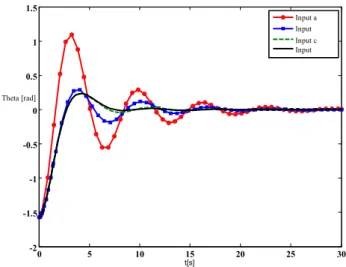
Fig. 3. Values for y, using the control signals, shown in Fig. 2
Fig. 4. Values for , using the control signals, shown in Fig. 2
In this section we are investigating the influence of the way the state-space is parti-tioned (four different ways of partitioning for four different values of d) to the values of the controlled parameters y(t) and (t). Fig. 3 and Fig. 4 show the outputs (y(t) and (t))
0 5 10 15 20 25 30 -2 -1.5 -1 -0.5 0 0.5 1 1.5 t[s] Input a Input Input c Input Theta [rad] 0 5 10 15 20 25 30 -12 -10 -8 -6 -4 -2 0 2 4 6 t[s] y Input Input b Input c Input d
for the four different inputs, given in Fig. 2-a,b,c,d, calculated respectively for the four different values of the parameter d. From the simulations it is evident that the smaller the value of this parameter is, the easier it is to achieve the control purpose. This certifies that partitioning the state space into appropriate regions plays a crucial role for the system performance.
5.CONCLUSION
We have used the model of a hovercraft vehicle for exploring the influence of the state-space partitioning into regions when designing appropriate switched fuzzy controllers. As the hovercraft vehicle is a typical nonholonomic nonlinear system, it can be easily concluded that the state-space partitioning into specific regions plays an important role in system performance when designing switched fuzzy controllers for a given system.
REFERENCES
1. G. Feng, “A Survey on Analysis and Design of Model-Based Fuzzy Control Systems”, IEEE
Transac-tions on Fuzzy Systems, vol. 14, no. 5, October 2006.
2. K. Tanaka, H. O. Wang, Fuzzy Control Systems Design and Analysis: A Linear Matrix Inequality
Ap-proach. New York: John Wiley & Sons, 2001.
3. H. Lin, P. J. Antsaklis, “Stability and Stabilizability of Switched Linear Systems: A Survey of Recent Results,” IEEE Transactions on Automatic Control, vol. 54, NO. 2, February 2009.
4. R. Palm, D. Driankov, “Fuzzy Switched Hybrid Systems - Modeling and Identification”, Proc. of the
IEEE ISIC/CIRA/ISAS Joint Conference, Gaithersburg, MD, September 14-17, 1998, pp. 130-135.
5. K. Tanaka, M. Iwasaki, H. O. Wang, “Stabilization of switching fuzzy systems,” in Proc. of Asian Fuzzy
System Symposium, 2000.
6. K. Tanaka, M. Iwasaki, H. O. Wang, “Stable switching fuzzy control and its application to a hovercraft type vehicle”, in Proc. of the Ninth IEEE International Conference on Fuzzy Systems, 2000, Vol. 2, pp. 804–809. 7. K. Tanaka, M. Iwasaki, H. O. Wang, “Stability and smoothness conditions for switching fuzzy systems,”
in Proc. of the 2000 American Control Conference, Chicago, Ilinois, June, 2000, pp. 2474-2478. 8. K. Tanaka, M. Iwasaki, H. O. Wang, “Switching Control of an R/C Hovercraft: Stabilization and
Smooth Switching,” IEEE Transactions on Systems, Man, and Cybernetics Part B: vol. 31, no. 6, De-cember 2001.
9. H. Ohtake, K. Tanaka, H. O. Wang , “Fuzzy modeling via sector nonlinearity concept,” Proc. of Joint 9th IFSA World Congress and 20th NAFIPS International Conference, Vancouver, 2001, pp. 127-132. 10. H. Ohtake, K. Tanaka, H. O. Wang, ”A construction method of switching Lyapunov function for
nonlin-ear systems,” in Proc. of the 2002 IEEE International Conference on Fuzzy System, 2002, pp. 221-226. 11. H. Ohtake, K. Tanaka, “Switching Model Construction and Stability Analysis for Nonlinear Systems,”
Journal of Advanced Computational Intelligence and Intelligent Informatics, Vol.10 No.1, 2006.
12. H. Ohtake, K. Tanaka, H. O. Wang, “Switching fuzzy control for Nonlinear Systems,” Proceedings of
the 2003 IEEE International Symposium on Intelligent Control, Houston, Texas, October, 5-6, 2003.
13. H. Ohtake, K. Tanaka, H. O. Wang, “Derivation of LMI design conditions in switching fuzzy control”, in Proc. of the 43rd IEEE Conference on Decision and Control, December 14-17, 2004, Vol.5, pp. 5100-5105. 14. H. Ohtake, K. Tanaka, H. O. Wang, “Switching fuzzy controller design based on switching Lyapunov
function for a class of nonlinear systems”, IEEE Transactions on Systems, Man, and Cybernetics, Part
B, Vol.36, Iss.1, pp. 13-23, February 2006.
15. H. Ohtake, K. Tanaka, H. O. Wang, “Switching fuzzy model construction and controller design with arbitrary switching planes”, in Proc. of the 2006 American Control Conference, Minneapolis, Minne-sota, USA, June 14-16, 2006, pp. 5053–5058.
16. H. Yang, G. M. Dimirovski, and J. Zhao, “Switched fuzzy systems: representation modeling, stability analysis, and control design,” in Proc. of the 3rd International IEEE Conference on Intelligent Systems, London, England, September 4-6, 2006, pp. 306-311.
17. H. Yang, G. M. Dimirovski, and J. Zhao, “Switched Fuzzy Systems: Representation Modelling, Stability Analysis and Control Design,” in Studies in Computational Intelligence 109, pp. 155-168, Springer-Ver-lag, Berlin Heidelberg, DE, 2008.
18. H. Yang, H. Liu, G. M. Dimirovski, J. Zhao, “Stabilization control for a class of switched fuzzy discrete-time systems,” in Proc. of the 2007 IEEE International Conference on Fuzzy Systems, London, England, July 23-28, 2007, pp. 1345-1350.
19. V. Ojleska, T. K.-Gugulovska, G. Dimirovski, “A Survey on Modelling, Analysis and Design of Switched Fuzzy Control Systems”, Proceedings of DECOM-IFAC’09, Ohrid, September 26-29, Macedonia.
20. V. Ojleska, T. K.-Gugulovska, G. Dimirovski, “Switched Fuzzy Control Systems: Exploring the Performance in Applications”, Proceedings of UKSim 4th European Modelling Symposium on Computer Modelling and Simulation, Pisa, Italy, November 17-19, 2010, pp. 37-42.
21. V. M. Ojleska, T. K.-Gugulovska, G. M. Dimirovski, “Influence of the State Space Partitioning into Regions when Designing Switched Fuzzy Controllers”, Proceedings of the X Triennial International SAUM Confer-ence on Systems, Automatic Control and Measurements - SAUM 2010, Niš, Serbia, November 10-12, 2010.
UTICAJ PODELE PROSTORA STANJA NA REGIONE
PRILIKOM PROJEKTOVANJA PREBACIVAČKIH FAZI
KONTROLERA
Vesna M. Ojleska, Tatjana Kolemishevska-Gugulovska,
Georgi M. Dimirovski
U ovom radu istražuje se uticaj podele prostora stanja u određenim regionima, prilikom projektovanja prebacivačkih fazi upravljača, na performanse stabilnosti sistema. Za svrhe ispitivanja projektovali smo prebacivački fazi model i odgovarajući prebacivački fazi upravljač za hovercraft vozila, kao tipični neholonomni sistem. Dizajn je napravljen za četiri različita načina podele prostora stanja. Rezultati simulacije verifikuju uticaj različitih podela prostora stanja na performanse upravljanja sistema.
Ključne reči: upravljanje, hibridni sistemi, fazi sistemi, prebacivački sistemi, prebacivanje,
![Fig. 1. The model of a hovercraft vehicle [5]](https://thumb-eu.123doks.com/thumbv2/9libnet/4051861.57265/3.892.342.555.797.914/fig-model-hovercraft-vehicle.webp)
![Fig. 2. Control inputs f R (t) and f L (t) and the appropriate switching signal, when the joined LMI conditions for stability and constraints on the control inputs, from [5]-[8], are used, for different values of the parameter d](https://thumb-eu.123doks.com/thumbv2/9libnet/4051861.57265/7.892.246.639.209.882/control-appropriate-switching-conditions-stability-constraints-different-parameter.webp)