CUSTOM HARDWARE OPTIMIZATIONS
FOR RELIABLE AND HIGH
PERFORMANCE COMPUTER
ARCHITECTURES
a dissertation submitted to
the graduate school of engineering and science
of bilkent university
in partial fulfillment of the requirements for
the degree of
doctor of philosophy
in
computer engineering
By
Hamzeh Ahangari
September 2020
Custom Hardware Optimizations for Reliable and High Performance Computer Architectures
By Hamzeh Ahangari September 2020
We certify that we have read this dissertation and that in our opinion it is fully adequate, in scope and in quality, as a dissertation for the degree of Doctor of Philosophy.
Özcan Öztürk(Advisor)
Uğur Güdükbay
Fazlı Can
Şenan Ece Schmidt
Süleyman Tosun
Approved for the Graduate School of Engineering and Science:
Ezhan Karaşan
Copyright Information
In reference to IEEE copyrighted material which is used with permission in this thesis, the IEEE does not endorse any of Bilkent University’s products or services. Internal or personal use of this material is permitted. If interested in reprinting/republishing IEEE copyrighted material for advertising or promo-tional purposes or for creating new collective works for resale or redistribution, please go to http://www.ieee.org/publications_standards/publications/ rights/rights_link.html to learn how to obtain a License from RightsLink.
©2015 IEEE. Reprinted, with permission, from H. Ahangari, G. Yalçın, Ö. Öztürk, Ö. Ünsal, and A. Cristal, “JSRAM: A circuit-level technique for trading-off robustness and capacity in cache memories,” IEEE Computer Society Annual Symposium on VLSI (ISVLSI), 2015.
©2016 IEEE. Reprinted, with permission, from H. Ahangari, I. Alouani, Ö. Öztürk, S. Niar, and A. Rivenq, “Register file reliability enhancement through adjacent narrow-width exploitation,” IEEE International Conference on Design and Technology of Integrated Systems in Nanoscale Era (DTIS), 2016.
©2017 IEEE. Reprinted, with permission, from H. Ahangari, I. Alouani, Ö. Öztürk, and S. Niar, “Reconfigurable Hardened Latch and Flip-Flop for FPGAs,” IEEE Computer Society Annual Symposium on VLSI (ISVLSI), 2017.
©2017 IEEE. Reprinted, with permission, from H. Ahangari, Y. I. Özkök, A. Yıldırım, F. Say, F. Atik, and Ö. Öztürk, “Analysis of design parameters in SIL-4 safety-critical computer,” IEEE Annual Reliability and Maintainability Symposium (RAMS), 2017.
©2020 IEEE. Reprinted, with permission, from H. Ahangari, F. Atik, Y. I. Özkök, A. Yıldırım, S. O. Ata, and Ö. Öztürk, “Analysis of Design Parameters in Safety-Critical Computers,” IEEE Transactions on Emerging Topics in Com-puting, 2020.
©2020 IEEE. Reprinted, with permission, from H. Ahangari, M. Özdal, and Ö. Öztürk, “HLS-based High-Throughput and Work-Efficient Synthesizable Graph Processing Template Framework,” IEEE Transactions on Parallel and Distributed Systems (TPDS), 2020 (submitted).
ABSTRACT
CUSTOM HARDWARE OPTIMIZATIONS FOR
RELIABLE AND HIGH PERFORMANCE COMPUTER
ARCHITECTURES
Hamzeh Ahangari
Ph.D. in Computer Engineering Advisor: Özcan Öztürk
September 2020
In recent years, we have witnessed a huge wave of innovations, such as in Artifi-cial Intelligence (AI) and Internet-of-Things (IoT). In this trend, software tools are constantly and increasingly demanding more processing power, which can no longer be met by processors traditionally. In response to this need, a diverse range of hardware, including GPUs, FPGAs, and AI accelerators, are coming to the market every day. On the other hand, while hardware platforms are becom-ing more power-hungry due to higher performance demand, concurrent reduction in the size of transistors, and placing high emphasis on reducing the voltage, altogether have always been sources of reliability concerns in circuits. This par-ticularly is applicable to error-sensitive applications, such as transportation and aviation industries where an error can be catastrophic. The reliability issues may have other reasons too, like harsh environmental conditions. These two problems of modern electronic circuits, meaning the need for higher performance and reli-ability at the same time, require appropriate solutions. In order to satisfy both the performance and the reliability constraints either designs based on reconfig-urable circuits, such as FPGAs, or designs based on Commercial-Off-The-Shelf (COTS) components like general-purpose processors, can be an appropriate ap-proach because the platforms can be used in a wide variety of applications. In this regard, three solutions have been proposed in this thesis. These solutions target 1) safety and reliability at the system-level using redundant processors, 2) per-formance at the architecture-level using multiple accelerators, and 3) reliability at the circuit-level through the use of redundant transistors. Specifically, in the first work, the contribution of some prevalent parameters in the design of safety-critical computers, using COTS processors, is discussed. Redundant architectures are modeled by the Markov chains, and sensitivity of system safety to parameters has been analyzed. Most importantly, the significant presence of Common Cause
v
Failures (CCFs) has been investigated. In the second work, the design, and imple-mentation of an HLS-based, FPGA-accelerated, high-throughput/work-efficient, synthesizable template-based graph processing framework has been presented. The template framework is simplified for easy mapping to FPGA, even for soft-ware programmers. The framework is particularly experimented on Intel state-of-the-art Xeon+FPGA platform to implement iterative graph algorithms. Beside high-throughput pipeline, work-efficient mode significantly reduces total graph processing run-time with a novel active-list design. In the third work, Joint SRAM (JSRAM) cell, a novel circuit-level technique to exploit the trade-off be-tween reliability and memory size, is introduced. This idea is applicable to any SRAM structure like cache memory, register file, FPGA block RAM, or FPGA look-up table (LUT), and even latches and Flip-Flops. In fault-prone conditions, the structure can be configured in such a way that four cells are combined together at the circuit level to form one large and robust memory bit. Unlike prevalent hardware redundancy techniques, like Triple Modular Redundancy (TMR), there is no explicit majority voter at the output. The proposed solution mainly focuses on transient faults, where the reliable mode can provide auto-correction and full immunity against single faults.
Keywords: Graph Processing, Hardened SRAM, Hardware Accelerator, High-Level Synthesis, IEC 61508, Markov Modeling, Reliability, Safety-Critical Com-puter, Redundancy, Xeon+FPGA.
ÖZET
GÜVENİLİR VE YÜKSEK PERFORMANSLI
BİLGİSAYAR MİMARİLERİ İÇİN ÖZEL DONANIM
OPTİMİZASYONLARI
Hamzeh Ahangari
Bilgisayar Mühendisliği, Doktora Tez Danışmanı: Özcan Öztürk
Eylül 2020
Son yıllarda, Yapay Zeka (AI) ve Nesnelerin İnterneti (IoT) gibi büyük bir ye-nilik dalgasına tanık olduk. Bu akımda, yazılım araçları sürekli artan işlem gücü talep ediyor ve bu artık geleneksel işlemciler tarafından karşılanamıyor. Bu ihtiyaca yanıt olarak, Grafik İşleme Üniteler (GPU’lar), Alanda Programla-nabilir Kapı Diziler (FPGA’lar) ve Yapay Zeka (AI) hızlandırıcılar dahil olmak üzere çok çeşitli donanımlar her gün piyasaya sürülüyor. Öte yandan, donanım platformları daha yüksek performans talebi nedeniyle daha fazla güce aç hale gelirken, eşzamanlı olarak transistör boyutunun küçülmesi ve voltajın azaltıl-ması, devrelerde her zaman güvenilirlik endişelerini arttırmıştır. Bu, özellikle bir hatanın felaketle sonuçlanabileceği ulaşım ve havacılık endüstrileri gibi hataya duyarlı uygulamalar için geçerlidir. Güvenilirlik konularının, sert çevre koşulları gibi başka nedenleri de olabilir. Modern elektronik devrelerin bu iki sorunu, yani aynı anda daha yüksek performans ve güvenilirlik ihtiyacı, uygun çözümler gerektirir. FPGA’lar gibi yeniden yapılandırılabilir devrelere dayalı tasarım veya genel amaçlı işlemciler gibi Piyasadan Hazır Temin Edilebilen (COTS) bileşen-lere dayalı tasarım uygun bir yaklaşım olabilir, çünkü bu platformlar çok çeşitli uygulamalarda kullanılabilir. Bu bağlamda, bu tezde üç çözüm önerilmiştir. Bu çözümler, 1) yedekli işlemciler kullanarak sistem düzeyinde güvenlik ve güvenilir-liği, 2) birden çok hızlandırıcı kullanarak mimari düzeyinde performansı ve 3) yedekli transistörlerin kullanımıyla devre düzeyinde güvenilirliği hedefler. Özel olarak, ilk çalışmada, Piyasadan Hazır Temin Edilebilen (COTS) işlemcileri kulla-narak güvenlik açısından kritik bilgisayarların tasarımında bazı yaygın paramet-relerin katkısı tartışılmıştır. Yedekli mimariler Markov zinciri kullanılarak mo-dellenmiştir ve sistem güvenliğinin parametrelere duyarlılığı analiz edilmiştir. En önemlisi, bu tür sistemlerde Yaygın Neden Arızalarının (CCF’ler) önemli varlığı araştırılmıştır. İkinci çalışmada, Yüksek Seviyeli Sentez (HLS) tabanlı, FPGA
vii
hızlandırmalı, yüksek verimli / iş verimli, sentezlenebilir şablon tabanlı grafik işleme ünitesinin tasarımı ve uygulaması sunulmuştur. Bu ünite yazılım program-cıları için bile FPGA ile kolay programlayabilme için basitleştirilmiştir. Sunulan yapı, yinelemeli grafik algoritmalarını uygulamak için özel olarak Intel’in son teknoloji ürünü Xeon + FPGA platformunda denenmiştir. Yüksek verimli boru hattının yanı sıra, iş verimli mod, yeni bir etkin liste tasarımıyla toplam grafik işleme süresini önemli ölçüde azaltır. Üçüncü çalışmada, güvenilirlik ve bellek boyutu arasında tercih yapmak için devre düzeyinde yeni bir teknik olan Ortak SRAM hücresi tanıtılmıştır. Bu fikir, ön-bellek, kayıt dosyası, FPGA BRAM veya FPGA arama tablosu (LUT) ve hatta mandallar ve Flip-Floplar gibi her-hangi bir SRAM yapısı için de uygulanabilir. Hataya eğilimli koşullarda, yapı, dört hücrenin bir büyük ve sağlam bellek biti oluşturmak üzere devre seviyesinde birleştirileceği şekilde yapılandırılabilir. Üçlü Modüler Yedeklilik (TMR) gibi yaygın donanım yedekliliği tekniklerinin aksine, belirgin bir seçim ünitesi yoktur. Çözüm, temel olarak, güvenilir modun otomatik düzeltme ve tek hatalara karşı tam bağışıklık sağlayabildiği geçici hatalara odaklanır.
Anahtar sözcükler: Çizge İşleme, Güçlendirilmiş SRAM, Donanım Hızlandırıcı, Üst Düzey Sentez, IEC 61508, Markov Modelleme, Güvenilirlik, Güvenlik Açısın-dan Kritik Bilgisayar, Yedeklilik, Xeon+FPGA.
Acknowledgement
The past years at Bilkent University will be a part of the most memorable, pleas-ant, and fruitful years of my life. The productive academic activities and peaceful life on the campus, which will always be like home to me, will forever be part of my memories. After endless thanks to God Almighty, for all his graces and mercies in all stages of my life, I would like to thank all people, who with their valuable support and assistance, completion of this thesis was made possible.
First and foremost, I would like to express my sincere and deep gratitude to my advisor Prof. Özcan Öztürk for his invaluable and continuous support, understanding, and guidance during my Ph.D. study and research. It has always been a pleasure for me to work with him. Second, I would like to thank the members of my thesis committee, Prof. Mustafa Özdal, Prof. Süleyman Tosun, and Prof. Uğur Güdükbay for spending valuable time on meticulously reading each and every progress report. Also, I convey my thanks to Prof. Fazlı Can and Prof. Şenan Ece Schmidt for accepting to read and review this thesis, and their insightful comments and suggestions.
I am grateful to the Bilkent CS department for the facilities they provided, especially financial support during my study. It was an honor and a privilege to be a member of the Bilkent CS family, and I would like to thank each member of the department. I would like to thank all of my office mates, particularly Naveed UI Mustafa, for the friendly and constructive times we spent together. I would like to thank the Scientific and Technological Research Council of Turkey (TÜBİTAK) 1001 program for supporting me during my Ph.D. studies in the EEEAG-115E835 project.
Above all, I would like to thank my family, especially my dear wife, Hajar, for her everlasting love, endless support, and understanding.
Contents
1 Introduction 1
1.1 Research Problems and Motivations . . . 2
1.2 Contributions . . . 5
1.3 Outline . . . 8
2 Analysis of Design Parameters in Safety-Critical Computers 9 2.1 Introduction . . . 9
2.2 Related Works and Motivation . . . 10
2.3 Safety Parameters In Our Analysis . . . 12
2.3.1 Processor Failure Rate . . . 13
2.3.2 Common Cause Failure (CCF) . . . 13
2.3.3 Failure Diagnostic Coverage . . . 14
2.3.4 Test and Repair . . . 15
2.4 Base Systems . . . 17
2.4.1 Assumptions . . . 17
2.4.2 Default Parameters . . . 18
2.4.3 Markov Models . . . 19
2.5 Experimental Results and Discussion . . . 24
2.5.1 Reliability and Availability . . . 25
2.5.2 Safety Sensitivity Analysis . . . 27
2.6 Approximate Rate Calculation on Markov Chain . . . 36
2.7 Summary . . . 39
3 HLS-based High-Throughput and Work-Efficient Synthesizable Graph Processing Template Framework 40
CONTENTS x
3.1 Introduction . . . 40
3.2 Background . . . 43
3.2.1 FPGA or GPU? . . . 43
3.2.2 Hardware Accelerator Research Program (HARP) Platform 44 3.2.3 Graph Processing . . . 45
3.3 Related Work . . . 48
3.4 OpenCL-based Design . . . 50
3.4.1 High-performance OpenCL for FPGA . . . 51
3.4.2 OpenCL implementation options . . . 52
3.4.3 OpenCL for FPGA: conclusion . . . 54
3.5 Template-based accelerator architecture . . . 54
3.5.1 High-throughput mode . . . 55
3.5.2 Work-efficient mode . . . 58
3.5.3 User programming interface . . . 61
3.6 Experimental Evaluation . . . 62
3.6.1 Experimental Setup . . . 62
3.6.2 Results . . . 65
3.7 Summary . . . 72
4 Reliable and Reconfigurable SRAM Cell and Flip-Flop 74 4.1 Introduction . . . 74
4.2 Background . . . 76
4.2.1 Static Noise Margin and Bit Error Rate . . . 77
4.2.2 SEU, MBU, and Soft Error Rate . . . 77
4.2.3 Fault sources in SRAMs . . . 78
4.3 Related works and discussion . . . 80
4.4 JSRAM structure . . . 85
4.4.1 Circuit Description . . . 85
4.4.2 Joiner Switch . . . 86
4.4.3 Various Layouts and Applications . . . 86
4.4.4 Static Noise Margin Improvement . . . 88
CONTENTS xi
4.4.6 Auto-Correction and Fault Immunity . . . 91
4.4.7 Read/Write Operations, Decoder Modification . . . 92
4.5 JLatch and JFF . . . 94
4.6 Overheads . . . 97
4.7 Register File Reliability Enhancement . . . 97
4.8 Experimental Evaluation . . . 98
4.8.1 Setup . . . 98
4.8.2 SNM Improvement . . . 98
4.8.3 Automatic Error Correction . . . 102
4.8.4 Soft-Error Rate Improvement . . . 102
4.8.5 Comparison between JFF and TMR-FF . . . 106
4.9 Summary . . . 107
5 Conclusion 109
List of Figures
1.1 Conventional static memory bit made by two cross-coupled invert-ers in: standard single-port 6T SRAM cell(left), and D-latch(right). 5 2.1 Safety goal should be achieved by the most economical
improve-ment. . . 11
2.2 β models for duplicated and triplicated systems [1]. Here, β2 = 0.3 of β, while β is split into 0.3β + 0.7β. . . 14
2.3 Illustration of test-repair abbreviations in safety standards [2, 3]. Top: online test, bottom: proof test. . . 16
2.4 High level view of triplicated and duplicated systems. . . 17
2.5 Unsafe (hazardous) and safe failure rate. . . 19
2.6 Markov model for 1oo1 (single) system. . . 22
2.7 Markov model for 1oo2 system. . . 23
2.8 Markov model for 2oo3 system. . . 25
2.9 Reliability functions for base systems. . . 26
2.10 Steady state operational availability value for base systems with β variation (1oo1 is not shown). . . 26
2.11 Effect of λP E variation over safety. . . 27
2.12 Effect of β variation over safety. . . 29
2.13 Effect of β2 variation over safety. . . 29
2.14 Effect of Cself test variation over safety. . . 30
2.15 Effect of ki variation over safety. . . 31
2.16 Effect of kc variation over safety. . . 32
2.17 Simultaneous improvement of β-factor and kc to reach SIL4 level. 32
LIST OF FIGURES xiii
2.19 Effect of online repair rate variation over safety. . . 33 2.20 Effect of proof-test rate variation over safety. . . 34 2.21 An intermediate state is added to Markov chain, in which a DD
failure has not been detected yet. . . 35 2.22 Effect of δ (= 1/tD) variation over safety. . . 35
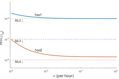
2.23 Simple models for measuring CCF2 and CCF3 influences. λ = λP E, µ = µP T. . . 36
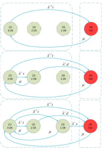
2.24 A simple model for 1oo3 configuration. . . 37 2.25 Transition paths with longer CCF jumps are added one by one
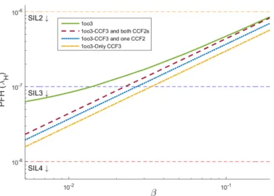
from top to bottom. . . 38 2.26 Comparison between complete and simplified Markov chains of
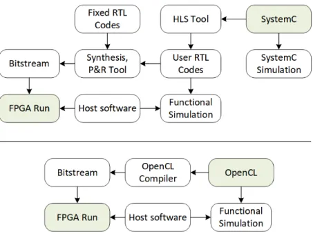
1oo3 system. . . 39 3.1 Intel Xeon+FPGA platform. . . 44 3.2 FPGA design flow using SystemC (top) and OpenCL (bottom) for
Xeon+FPGA platform. . . 45 3.3 Pseudo-code for doubly nested loops (vertex-centric) at the top
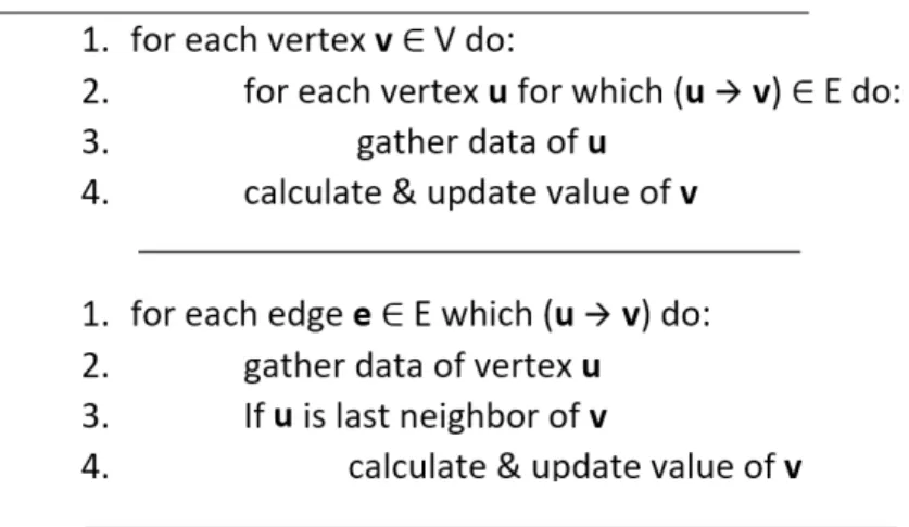
versus a single flat loop (edge-centric) at the bottom used in OpenCL implementation. . . 53 3.4 Simplified diagram of one high-throughput deeply pipelined vertex
processing accelerator. . . 57 3.5 Simplified diagram of one work-efficient deeply pipelined vertex
processing accelerator. . . 59 3.6 Multi-level bit-vector architecture in the basic version, where list
resolution is one vertex. . . 60 3.7 Saturation of off-chip memory bandwidth and throughput, with
the number of accelerators (Delaunay). . . 66 3.8 Average throughput for the OpenCL implementation of BFS with
different datasets and different number of accelerators. . . 67 3.9 Average throughput for the OpenCL implementation with different
datasets on 4 accelerators. . . 68 3.11 Average run-time per iteration for OpenCL vs. template HT. . . . 68 3.10 Peak throughput of OpenCL vs. Template-based HT. . . 69
LIST OF FIGURES xiv
3.12 Average run-time per iteration of WE template normalized with respect to HT template. . . 70 3.13 Average energy consumption per iteration, for HT vs. WE. . . 70 4.1 Distribution of logic blocks, on-chip memory blocks, routing switch
matrices, and I/O blocks inside a generic FPGA architecture. . . 75 4.2 SNM degradation due to (a) Vdd scaling (b) process variation [4]. 79
4.3 JSRAM is a robust cell implemented by combining four SRAM cells like a ring. . . 85 4.4 Variants of JSRAM layout. . . 87 4.5 Standard read operation in SRAM. . . 88 4.6 a) Voltage division on Vdd-gnd path in normal read operation
in-creases ‘0’ voltage in node P A. b) Parallelizing pull-down transis-tors of two cells increases β ratio of JSRAM. . . 89 4.7 a) Hitting particle charges node capacitor and then, node voltage
rises. b) Node capacitor and discharging path of cell B is added to cell A to discharge faster. . . 90 4.8 Durable fault propagates from cell A to D. Cell B and C are not
affected and later will recover cell A and D. . . 92 4.9 Reconfigurable decoder for layout of Figure 4.4(a). Gray gates
have been added. . . 93 4.10 Three typical implementations for static latch. . . 95 4.11 JLatch is a reconfigurable hardened static latch implemented by
joining outputs of four latches like a ring. . . 96 4.12 JDFF (Joint D Flip-Flop) is built from two JDLatches (Joint D
Latches) on the left. This structure provides four separate nor-mal DFF or a single radiation hardened DFF. Conventional TMR technique on the right. . . 96 4.13 JSRAM with identical static noise sources inserted into cell A. . . 99 4.14 Improvement in JSRAM’s Read-SNM with different joiner types
and sizes over a typical 6T SRAM. . . 100 4.15 Improvement of JSRAM’s Hold-SNM with different joiner types
LIST OF FIGURES xv
4.16 Graphical demonstration of Read-SNM (Butterfly diagram). (a) 6T SRAM cell (b) JSRAM with imaginary 0-ohm joiner. Hystere-sis behavior causes SNM to go beyond Vdd/2. . . 101
4.17 Self error correction in JSRAM with NMOS1 joiner. . . 103 4.18 Particle strike is modeled by current injection into circuit nodes. . 105 4.19 JSRAM: maximum tolerable amplitude of injected current pulse,
for every pulse width on x-axis. . . 105 4.20 JLatch: maximum tolerable amplitude of injected current pulse,
for every pulse width on x-axis. . . 106 4.21 Comparison between delay of a normal DFF, a triplicated DFF
with a majority voter at output (TMR DFF), and a Joint-DFF (JDFF). . . 107
List of Tables
1.1 Safety levels in IEC 61508 standard for high demand/continuous systems (PFH: average frequency of a dangerous failure of safety
function per hour, SIL: Safety Integrity Level) [2]. . . 3
2.1 Default values for safety design parameters. . . 18
2.2 Other abbreviations and symbols. . . 21
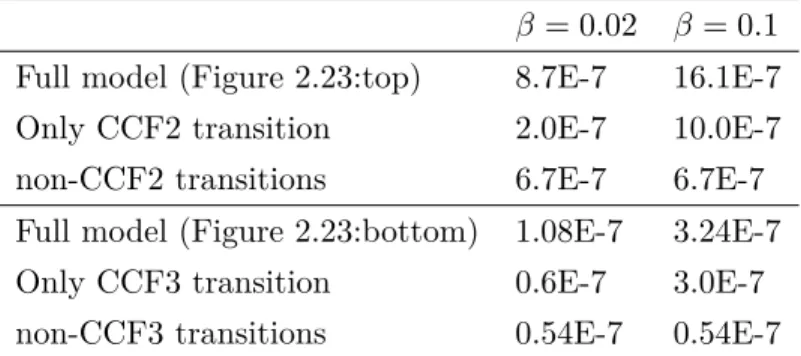
2.3 Failure rates of systems in Figure 2.23 for three scenarios. . . 37
3.1 Graph datasets used in experiments. . . 64
3.2 The number of vertices converged in the first four iterations of BFS. 66 3.3 FPGA resource utilization. . . 71
Chapter 1
Introduction
In modern times, computers have been invented to help humans. The compu-tational power of these calculating machines is millions of times faster than the power of the human brain. Traditionally, designed software algorithms run upon these machines. However, with the rapid development of information technology, artificial intelligence and numerous branches of science, this traditional approach has changed. Software running on general-purpose processors is no longer the only solution that meets the growing needs for higher computation power, less power consumption, more accuracy, and more reliability. In many applications, cus-tomized hardware, designed specifically for a specific purpose, are a great help to processors. Widely used multimedia encoders and decoders, graphic accelerators, cryptographers, artificial intelligence accelerators, and many more are examples of such hardware, designed to provide higher computational power beyond the conventional processors.
Processors and other hardware, particularly designed for error-sensitive appli-cations such as passenger planes, trains, satellites, and military equipment are other examples of the need for special, non-generic, and usually expensive hard-ware. On the other hand, in recent years, long time-to-market and costly design processes have made customized hardware not to be affordable for designs with limited production volume. Instead, using Commercial Off-The-Shelf (COTS)
components is the prevalent approach, where hardware systems based on com-mercial devices such as generic processors, or field-programmable gate arrays (FPGAs) are widely used in the industry. Therefore, having reliability solutions based on COTS components can be economically beneficial. In this dissertation, we consider the design of specific hardware to help increase the safety, reliability, or performance. Our solutions are targeting these objectives on three different levels, namely, system-level, architecture-level, and circuit-level. In all of the pro-posed techniques, we utilize resource replication, including data, processors, or accelerators.
1.1 Research Problems and Motivations
Nowadays, safety-critical computers are obligatory constituents of many elec-tronic systems that affect human life safety. Several areas of the transportation industry like railways, avionics, and automotive, increasingly use such systems. To design a computer for safety-critical applications, industrial safety levels such as international safety standard IEC 61508 (shown in Table 1.1) have been set. In this domain, safe microcontrollers with limited processing capabilities are avail-able in the market for mostly control purposes. However, as systems become more and more complex and versatile, having safe processors with intensive processing capabilities becomes an essential need. According to IEC 61508-2 standard, a single processor can achieve at most Safety Integrity Level 3 (SIL3). In most cases, safety-critical applications in civil domains require a higher level of safety, such as SIL4. Hence, to answer this eminent need, a computing platform needs to be architected in system-level with safety in mind. In order to achieve such high standards, it is necessary to make improvements in numerous aspects of a general-purpose system. The reliability of electronic components is the most ob-vious factor that needs to be satisfied when building a robust system. Besides, clever system design by means of available electronic components is as important as the quality of components themselves. Even with reliable and robust parts, safety goals may not be achieved without a safety aware design process. Preva-lent design issues like a perfect printed circuit board, EMC/EMI isolation, power
10−9 6 PFH of SIL4 < 10−8 10−8 6 PFH of SIL3 < 10−7 10−7 6 PFH of SIL2 < 10−6 10−6 6 PFH of SIL1 < 10−5
Table 1.1: Safety levels in IEC 61508 standard for high demand/continuous
systems (PFH: average frequency of a dangerous failure of safety function per hour, SIL: Safety Integrity Level) [2].
circuitry, failure rates of equipment, etc., are examples of common quality con-siderations. However, in critical systems, in addition to these, some other less obvious issues have to be observed. Chapter 2 is dedicated to elaborate on design parameters of safety-critical computers.
Recent years have seen a massive interest in Artificial Intelligence (AI), due to a sharp increase in demand from industry, such as security, finance, health-care, and military. In many applications, AI helps substantially by providing higher levels of precision and improving productivity. In this enormous wave of evolution, many companies, including giants of the computer industry, invest considerable resources in AI technology. As we see, new software and hardware products are released daily, including FPGA accelerated CPUs, deep-learning models, neural network accelerators, and AI SDKs targeting a various range of hardware platforms, from CPU and GPU to FPGA and VPU. Meanwhile, graph theory, as one of the most fundamental modeling techniques in data science, con-tributes to many of the current AI applications. Specifically, graphs provide a better context for machine learning algorithms due to the way data is organized, enabling relationships of numerous degrees to be analyzed quickly. Problems that can be modeled as communicating entities, such as the Internet of Things (IoT), social networks, web search, transportation, health-care systems [5], and even biology [6] are examples for which graph data models are an excellent fit. Many of these AI algorithms, such as deep-learning-based computer vision, are not only compute-intensive but also operate on enormous data-sets. According to official statistics, as of the first quarter of 2019, Twitter had more than 330 million monthly active users, with more than 500 million total number of tweets per day [7]. Having strong support from the underlying hardware to accelerate
software algorithms has become an indispensable requirement in many applica-tions due to the widespread usage of AI on huge data-sets. FPGAs, GPUs, and emerging novel hardware devices, such as neural network accelerators, have started to play a shining role in AI execution. Graph applications are among the important algorithms used in AI and ML implementations since iterative model training is one of the greatest challenges. Concurrent nature of graph models -as vertices/edges represent concurrent entities/links- provides large parallelism po-tentials. However, efficiently implementing these applications on existing systems is not trivial. Therefore, having an efficient co-processor-based graph processing is considered as a promising solution for the growing need for graph applications within the AI domain. Graph processing acceleration on FPGA is discussed in Chapter 3.
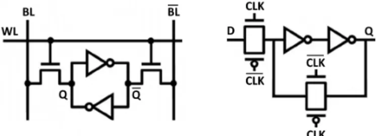
Today Static-RAM (SRAM) memory is the building block for the most critical processor structures such as cache and register file. Different levels of cache alto-gether occupy a large portion of die area in modern processors, where decreasing area and power consumption is highly desirable. However, scaling leads to stabil-ity problems more often in cache cells than in other parts of the processor [8]. In the case of Register-File (RF) story is quite different as registers are the fastest memory component with the smallest capacity in the memory hierarchy. Because of performance requirements, RF cells are larger, faster, and more reliable than those found in the cache. But, because of the higher access rate, chances of having transient errors and subsequent fault propagation are high [9]. In caches, ECC is an effective technique. However, unlike cache, due to timing and power overheads, ECC is not an appropriate solution for register file reliability. In RF, the activity rate per address is higher than cache memories, making power consumption more important. Additionally, RF is in the processor’s critical path and priority of performance is an essential necessity. Consequently, finding a suitable technique for RF reliability enhancement is a new kind of challenge when compared to cache memories. Latch and Flip-Flop (FF) are other essential digital storage elements that are used for sequential logic implementation. Although their access circuitry is somewhat different than SRAMs, nevertheless, the main data retention core is identical. All are made by two cross-coupled inverters to form static memory
Figure 1.1: Conventional static memory bit made by two cross-coupled
in-verters in: standard single-port 6T SRAM cell(left), and D-latch(right).
bit as shown in Figure 1.1. In Chapter 4, we aim at enhancing the reliability of static memories, to be used in a wide set of structures.
1.2 Contributions
Our solutions target 1) safety and reliability at the system-level using redundant processors, 2) performance at the architecture-level using multiple accelerators, and 3) reliability at the circuit-level through the use of redundant transistors. Emphasis on improving the performance of digital circuits to meet the grow-ing needs, at the same time, requires attention to reducgrow-ing power consumption. Because the improvement in performance is usually achieved by increasing the frequency or increasing the area, such as the number of parallel cores. In such cases, the increase in power consumption is inevitable which can draw a decisive limit. Due to the quadratic relationship between voltage and power, voltage scal-ing is one of the most effective ways to reduce power. However, as discussed in Chapter 4, at lower voltage levels, the stability of circuits is adversely affected, leading to a higher number of fault rates. Therefore, techniques to increase the reliability of circuits, particularly, at low voltage levels, can provide better op-portunities to increase the performance as well. The contributions in this thesis are proposed in different design levels. This provides the possibility of apply-ing all of them in a hierarchical way on the same system, to improve the safety, reliability, and performance at the same time. The circuit-level reliable SRAM cell (Chapter 4), which is applicable to FPGAs to improve the reliability, can be
employed in a graph accelerator on FPGA (Chapter 3). In this way, the graph accelerator can be used in critical applications. Similarly, the graph processing platform (Chapter 3), can be used as the processing element in safety-critical processor (Chapter 2). In this way, the graph processing platform can be used in safety-critical applications, such as avionics.
Resource replication is the key idea in all of the approaches presented in this thesis. More specifically, it has been shown how resource replication can provide higher levels of reliability, safety, and performance in computer systems. In the safety-critical processor (Chapter 2), multiple identical processors redundantly run in parallel. However, these processors run the same software to provide multiple order of magnitude increase in the safety and reliability levels, based on redundancy in processing. In graph accelerator for FPGA (Chapter 3), multiple identical accelerators run in parallel similarly. However, they divide and run the same task to enhance the processing power up to a saturation point. In reliable SRAM cell (Chapter 4), identical copies of a memory bit are preserved to build a fault-tolerant structure, using data redundancy.
Our redundancy-based contributions in this thesis, regarding the design of cus-tomized hardware for enhancing safety, reliability, and performance of computer systems, are listed more specifically in the following order: 1) system-level, 2) architecture-level, and 3) circuit-level.
• System-level: A sensitivity analysis of functional system safety to some critical design parameters in a system-level replication-based design of a safety-critical computer is introduced. Analysis is given for two fundamen-tal and widely used multi-channel safe configurations, 1oo2 and 2oo3, where a basic 1oo1 system is used as a baseline. All configurations have been mod-eled by Markov chains to examine at which safety integrity level (SIL) they stand, and how distant they are from the target level. In this way, each safety parameter’s contribution to safety can be understood. Through these measurements, instead of blindly improving an unsafe system, designers can make an informed decision to select the most appropriate parameter for im-provement. A significant presence of Common Cause Failures (CCFs), is
an important factor for analyses in this study.
• Architecture-level: A high-performance/work-efficient, SystemC based, synchronous, deeply pipelined, and fully synthesizable graph processing ar-chitecture, ready to be implemented on FPGA is proposed. The template-based framework is usable by non-hardware experts, such as IT engi-neers, to generate FPGA programs automatically, using only C/C++. The proposed framework is specifically tested on, and prepared for the Intel state-of-the-art Xeon+FPGA platform. However, it can be extended and adapted to other similar FPGA-based architectures. In work-efficient mode, a novel fast bit-vector to keep an active vertex list is introduced. The alternative HLS language option for FPGA, OpenCL, is investigated and contrasted to show limitations and difficulties of implementing high-performance pipelined graph algorithms by high-level languages.
• Circuit-level: A novel static memory cell is implemented to mitigate tran-sient faults. In the case of SRAM memory, we improve both the soft-error rate and the Vdd-induced fault rate at the same time. In the case of latch
and Flip-Flop, the soft-error rate is improved. This approach brings recon-figurability of reliability to static memory structures (SRAM, latch, and Flip-Flop) with fine granularity, where it is particularly useful for reconfig-urable fabrics like commercial-grade FPGAs to make them more suitable for critical applications. Additionally, the reliable mode can provide auto-correction and full immunity against single faults. Moreover, it efficiently can cope with Multiple Bit Upsets (MBUs). Unlike prevalent hardware redundancy techniques, like Triple Modular Redundancy (TMR), there is no explicit majority voter at the output, in this technique. Consequently, voter failure and latency are of less concern. Moreover, the adjacent cell immediately recovers the faulty bit value to avoid degradation in redun-dancy. Based on a similar idea and as a typical application, we propose a new approach to exploit vacant spaces in a Register-File (RF) to keep redundant data for better robustness.
1.3 Outline
The remainder of this dissertation is organized as follows. In the next chap-ter, analysis of design parameters in safety-critical computers is presented. The motivation for having sensitivity analysis, a list of considered design parame-ters, Markov modelings, and sensitivity simulation results are discussed in this chapter. In Chapter 3, the architecture of the HLS-based high-throughput and work-efficient synthesizable graph processing template framework is proposed. Background of graph processing, Intel Xeon+FPGA platform, and HARP pro-gram are presented in this chapter. Furthermore, different high level synthesis (HLS) language options for FPGAs (OpenCL and SystemC), proposed architec-tures for high-throughput and work-efficient modes, and evaluation results are also given here. In Chapter 4, the joining technique to build reliable and recon-figurable static memory elements is proposed. Common fault sources in static memories (such as voltage scaling, process variation, noise, and radiation), the structure of joining technique, improvements, and evaluation results are presented in this chapter. Finally, the thesis is concluded in Chapter 5.
Chapter 2
Analysis of Design Parameters in
Safety-Critical Computers
2.1 Introduction
Redundancy, meaning having multiple processors (channels) doing the same task, is required by safety standards in many cases. The ratio of Common Cause Fail-ures (CCFs), defined as the ratio of concurrent failure rate (simultaneous failFail-ures among redundant channels) over total failure rate, has great impact on system safety. The percentage of failures the system is able to detect by means of fault detection techniques also has a direct effect on safety. This is because undetected failures are potential dangers. To remove such undetected failures, an important factor is the frequency and the quality of system maintenance. Frequency and comprehension of the system tests (automatically or by technicians) to repair or replace the impaired components, can guarantee the required safety level by removing transient failures or refreshing worn-out parts.
As safety is a very wide subject, the main objective of this work is to inves-tigate the sensitivity of system safety, affected by random hardware failures, to
some crucial design parameters [10, 11]. Three widespread configurations; 1oo1, 1oo2, and 2oo3; with known values of parameters, are assumed as base systems. For these systems, we evaluated individual parameters that contribute to safety. In this work, we target high demand/continuous systems, where the frequency of demand to run the safety function is more than one per year, unlike low demand systems where it is less than one per year [2]. Average frequency of a danger-ous failure of safety function per hour (PFH), is the safety measure for high demand/continuous systems, while probability of failure on demand (PFD), is the measure for low demand systems. PFH is defined as average rate of entering into unsafe state, while PFD is defined as probability of being in unsafe state.
This chapter is organized as follows: In Section 2.2, some of the recent or relevant works are reviewed and our motivation is given in more detail. In Section 2.3, definition and modeling for considered design parameters are described. In Section 2.4, base systems and their Markov modeling are proposed. In Section 2.5, experimental results are discussed, while Section 2.6 discusses a simplified Markov modeling in safety calculations. Finally, a summary is given in Section 2.7.
2.2 Related Works and Motivation
During the design process, concentrating on multiple aspects of design altogether for the purpose of improvement can be complicated. Normally, if the prototype design does not meet the requirements, it is rational to find the system’s bottle-neck and focus on it. In safety-related designs, by knowing the share that each parameter provides to safety, the designer can decide where to put more emphasis to improve the outcome with the least amount of effort. Here, we discuss some of the safety-critical computer system designs in literature, which considered a subset of safety design parameters due to complexity.
In [12], authors designed a redundant computer system for critical aircraft control applications, and an acceptable level of fault tolerance is claimed to be
Figure 2.1: Safety goal should be achieved by the most economical
improve-ment.
achieved with using five redundant standard processors, extensive error detection software and fault isolation mechanism. In [13], dual-duplex and Triple Modular Redundancy (TMR) synchronous (with common clock signal) computer systems have been built using military and commercial electronic parts. While authors tried to improve the system safety, the effect of CCFs is not assessed, where this effect can be significant in synchronous systems. Besides, the achieved safety level is not compared to any standard level. In microcontroller-based SIL4 soft-ware voter [14], SIL4 level is claimed to be obtained with a duplex architecture. Nevertheless, neither failure coverage, nor CCFs are assessed in sufficient details. Similarly, in [15], authors target safe computer system for a train, which is not compared to standard levels, and does not consider CCFs or diagnostic coverage. These approaches, either lack in considering some of the most influential safety design parameters or methodology to assess the system safety level with respect to standards. Thus, these studies are incomplete to be considered for real safety-critical applications due to complexity of taking all parameters into account. This stimulated us to have an analysis on a few safety architectures also used in above studies. By showing the sensitivity of safety to each such parameter, we aim to provide a comparative understanding of these occasionally ignored parameters. This can help practitioners to select the most appropriate parameter for improving the safety. Depending on the constraints, the most appropriate parameter can be
translated to the one that leads to cheapest, fastest, or easiest system modification (as shown in Figure 2.1).
In [16], authors model a safety-related system in low demand mode using Markov chain to calculate PFD measure, in a way that is explained in the respec-tive standard [3]. Several parameters such as CCF, imperfect proof testing, etc. are integrated into the model to investigate their influence over safety. However, in our work, we focus on PFH, where its calculation is not as straightforward as PFD. Moreover, we include additional parameters such as frequency of online testing, self-testing, etc., with sensitivity analysis for each parameter.
There have been many efforts related to generalized and simplified PFH for-mula for M-out-of-N (MooN) architectures. The works proposed in [17, 18] de-velop a set of analytical expressions with some assumptions and parameters dif-ferent than ours, like considering partial proof test, slightly taking the CCF con-tributions into account or dealing with dangerous detected failures differently. In [19], probabilistic analysis of safety for MooN architectures is proposed when considering different degrees of uncertainty in some safety parameters such as failure rate, CCFs, and diagnostic coverage, by combining Monte Carlo sampling and fuzzy sets. Emphasizing the significance of CCF impact over safety in re-dundant systems, in [20], authors explore the criticality of beta-factor on safety calculations. Specifically, they address PFD measure for a typical 1oo2 system. Influence of diversity in redundancy (i.e. implementing redundancy with compo-nents technologically diverse) over CCF is assessed in [21] by a design optimization approach for low demand systems.
2.3 Safety Parameters In Our Analysis
In this section, we review the definition and modeling of design parameters that effect safety. It is assumed that the safety-critical computer system is composed of multiple redundant processors since such replication is recommended by safety standards.
2.3.1 Processor Failure Rate
A safety-critical computer system is composed of one or more redundant proces-sors, connected to each other by communication links. We may also call them as channels or programmable electronics (PEs) according to the safety standards terminology. Generally, there is no extraordinary requirement regarding reliabil-ity of PEs. Due to low quantreliabil-ity and high cost of these systems, components are not necessarily designed for reliability purposes. Most often, a PE is a standard processor module, built from available Commercial-Off-The-Shelf (COTS) elec-tronic parts including processor, memory, power circuitry, etc. In this study, we take a PE as a black box, assuming it comes with a single overall failure rate, λP E.
2.3.2 Common Cause Failure (CCF)
According to IEC 61508-4 standard [2], Common Cause Failure (CCF, or depen-dent failure) is defined as concurrent occurrence of hardware failures in multiple channels (PEs) caused by one or more events, leading to system failure. If it does not lead to a system failure, it is then called common cause fault. The β factor represents the fraction of system failures that is due to CCF. Typically, for a duplicated system, β value is around a few percent, normally less than 20%. In safety standards, two β values are defined for detected and undetected failures (βD and β), while here we only assume a single β value for both. Assuming that
the CCF ratio between two PEs is taken as β, by using the extended modeling and notations shown in [1], we make the following observations for all systems in this work:
• 1oo1 configuration: Since there is no redundant PE, β1oo1 = 0.
• 1oo2 configuration: As depicted in Figure 2.2, the β of system is only related to CCFs between two PEs. Therefore, β1oo2 = β.
is related to mutual CCFs, plus CCFs shared among all three PEs. Note that by definition, the CCF ratio between every two PEs is taken as β. The β2 is defined as a number in [0, 1] range, expressing part of β which
is shared among all three PEs [1]. For a typical 2oo3 system, we assume β2 = 0.3 of β, making β2oo3 = 2.4β (see Figure 2.2).
The two parameters, β and β2, indicators of mutual and trilateral PEs
isola-tion, are evaluated in our analysis.
Figure 2.2: β models for duplicated and triplicated systems [1]. Here, β2 = 0.3
of β, while β is split into 0.3β + 0.7β.
2.3.3 Failure Diagnostic Coverage
According to IEC 61508-4 [2], Diagnostic Coverage (C or DC) is defined as the fraction of failures detected by automatic online testing. Generally two com-plementary techniques are employed to detect failures, self-testing and compar-ison. Self-testing routines run upon each PE to diagnose occasional failures au-tonomously and they usually detect absolute majority of failures, normally around 90%. Second diagnostic technique is data comparison among redundant PEs for detecting the rest of the undetected failures. Hence, generally we can express C as:
C = Cself test+ Ccompare ≈ 1
C rate. According to the referred formulation, the total C is expressed as: C = Cself test+ (1 − Cself test) · k
More specifically, k is the efficiency of comparison test. Since the comparison method is more effective against independent failures (non-CCFs), it is reasonable to differentiate between C rate of CCF and independent failures. Therefore, two variants of former expression can be derived:
Ci = Cself test+ (1 − Cself test) · ki
Cc= Cself test+ (1 − Cself test) · kc
Here ki and kc are two constants, 0 6 ki, kc
6 1, describing the efficiency of comparison for either of two classes of failures. Since comparison is less effective against CCFs, the kcvalue is low, generally less than 0.4, while ki can be close to
1 [22]. Therefore, normally Cc 6 Ci. Three representative parameters; C self test,
kc and ki; are used in our analysis.
2.3.4 Test and Repair
Based on the IEC 61508 standard, two forms of test and repair have to be acces-sible for safety systems: online test and proof test. In online test (or automatic test), diagnostic routines run on each PE periodically, while system is available. As soon as a failure is detected, the faulty PE (or in some configurations the whole system) is supervised to go into fail-safe mode to avoid dangerous output. Thereafter, system tries to resolve the failure with immediate call for personnel intervention or a self commanded restart without human intervention. For tran-sient failures, a system restart can be a fast solution, while for persistent failures switching to a spare PE or system, provides a faster recovery. In any case, online repairing is supposed to last from a few minutes to a few days. Repair rate is denoted by
µ
OT which is defined as 1/MRTOT (MRT : mean repair time). ThetD parameter is the time to detect a failure in online testing. There is no direct
reference to this parameter in the standard, probably because it is assumed to be negligible with respect to repair time. However, it has been considered in
literature [23]. MT T ROT (mean time to restoration) is mean total time to detect
and repair a failure (see Figure 2.3). Some systems may support partial recov-ery which means repairing a faulty PE, while the whole system is operational. Restarting only the faulty PE (triggered by operational PEs), can make it opera-tional again. However, if the fault is persistent, such recovery is not guaranteed. Three parameters tD,
µ
OT and availability of partial recovery are also consideredin our analysis.
Proof test (or offline test or functional test) is the second and less frequent form of testing, whereby the periodic system maintenance process is performed by technicians. During such a maintenance, system is turned off and deeply examined to discover any undetected failure (not detected by online diagnostics) followed by a repair or replacement of defective parts. Test Interval (T I) defines the time interval at which this thorough system checking is performed and is typically from a few weeks to a few years. In such a scenario, repair time is negligible relatively. MT T RP T is the mean time to restoration (detect and repair
as shown in Figure 2.3) from an undetected failure, and on average is taken as T I/2[3]. Proof test and repair rate is denoted by
µ
P T = 1/M T T RP T. Theµ
P Tis another parameter considered in our analysis.
Figure 2.3: Illustration of test-repair abbreviations in safety standards [2,3].
Figure 2.4: High level view of triplicated and duplicated systems.
2.4 Base Systems
In this section, we define two prevalent safety configurations, 1oo2 and 2oo3 plus simple 1oo1 as a reference, for our analyses. Configurations are modeled by Markov chain with employing all the aforementioned parameters. The assigned set of default values for parameters specify the initial safety point for each system.
2.4.1 Assumptions
In this study, we make the following assumptions: Typically, a safe computer is responsible for running user computations. At the same time, it is in charge of checking the results for possible failures and taking necessary measures (in other words, running safety function). Specifically, the safety function of the system detects and prevents any erroneous calculation result on PEs. All PEs are asynchronous and identical (homogeneous) and connected to each other by in-system links, whereby software voting and comparison mechanisms operate (Figure 2.4). In this work, our focus is on processors (PEs), while I/O ports and communication links are assumed to be black-channel, by which safety is not affected. This assumption can be realized by obeying standards applied for safe communication over unsafe mediums (e.g. EN-50159). These systems are assumed to be single-board computers (SBCs), meaning all redundant PEs reside on one board. Online repair of a PE with detected failures makes it operational again, but a PE with undetected failures can be repaired only by proof test and repair. Moreover, for biasing a high demand/continuous system toward safety,
degraded operation is not allowed. It means when a failure is detected, the faulty PE activates its fail-safe output and contributes to voting (alternatives are 1)to report the failure but keep the PE’s output silent, leading to degradation of system, for example from 1oo2 to 1oo1, or 2)not to tolerate any faulty PE [17]). A PE with undetected failure is assumed to be seemingly operational and able to run diagnostic routines. Another simplifying assumption is that a CCF occurs in a symmetric way across PEs in a way that it is detectable on all PEs or on none of them.
2.4.2 Default Parameters
For safety parameters which we intend to investigate in this study, we assign a set of default values to define an initial safety point for each system (shown in Table 2.1). In our experiments, we sweep each parameter around the default value and illustrate how safety is affected. This way, the sensitivity of system safety with respect to that parameter will be revealed. Although in implementing a system some parameters such as β and β2, or kc and ki, may not be practically
independent, we disregard this dependency which is due to implementation.
Parameter Meaning Default value λP E PE failure rate 1.0E-5/hour
Cself test Diagnostic coverage of self-testing [22] 0.90
ki Comparison efficiency for 0.90 independent failures [22]
kc Comparison efficiency for CCFs [22] 0.40 β CCF ratio between each two PEs 0.02 β2 Part of β shared among three PEs [1] 0.3
tD Time to detect failure by online test 0 (negligible)
(inverse of online test rate)
µOT Online repair rate 1/hour
µP T Proof test and repair rate 0.0001/hour
(≈ 1/year)
Figure 2.5: Unsafe (hazardous) and safe failure rate.
2.4.3 Markov Models
In this section, we give our safety configurations modeled by Markov chain. RAMS (Reliability, Availability, Maintainability and Safety) measures are calcu-lated according to guidelines suggested in ISA-TR84.00.02 [3] and IEC 61165 [24] standards, along with previous studies [25]. States are divided into two main categories; ‘up’ (or operational) and ‘down’ (or non-operational). In up states, the system is able to correctly run the safety functions. Up state is either all-OK initial state or any state with some tolerable failures. Down states are those in which system is not able to correctly run safety functions, either intentionally as in the fail-safe state or unintentionally as in unsafe (hazardous) state. Sys-tem moves into fail-safe/unsafe state if there are intolerable number of dangerous detected/undetected failures present.
As soon as a dangerous failure is detected, system may either tolerate it (like the first detected failure in 2oo3 system) or enter into fail-safe state. On the other hand, if the failure is left undetected, system may inadvertently tolerate it (like first undetected failure in 1oo2 or 2oo3 systems) or enter into unsafe (hazardous) state.
PFH is defined as the average rate of entering into an unsafe state. For safety calculation purposes, repair transitions from unsafe states toward up states should
not be considered [24]. Additionally, as in the case of reliability calculation, we also remove repairs from down fail-safe states to account only the effective safety when system is operational. Note that the repairs inside up states are not re-moved. All of the following Markov models are in the full form before repair removal. From the total failure rate of each system, λsys, only the hazardous
part, λH, should be considered (as shown in Figure 2.5). By definition, PFH is
calculated as the average of λH. The details of the following formula, required for
decomposing λsys into λH and λS, is explained in the literature [26](PH:
Prob-ability of being in hazardous state, PS: Probability of being in fail-safe state,
PHS = PH + PS, PHS0 : derivative of PHS with respect to time):
λH =
PHS0 1 − PHS
· PH PHS
Generally, probabilities of the system over time is described with the following set of differential equations:
P1×n0 = P1×n· An×n
where P is vector of state probabilities over time, P0
is derivative of P with respect to time, n is number of states, and A is transition rate matrix. Abbrevi-ations used in Markov chains are listed in Table 2.2.
1oo1 Configuration: The single system is composed of a single PE without
any redundancy. Hence, all failures are independent (non-CCF) and can only be detected by self-testing. If failure is detected, next state is fail-safe, otherwise it is unsafe (Figure 2.6). Transition terms for 1oo1 system are (ki = 0, Ci = C
self test
):
λDDs = Ci· λP E
λDUs = (1 − Ci) · λP E
λDs = λDDs + λDUs = λP E
D Dangerous failure, a failure which has potential to put system at risk (only such failures are considered in this work).
C Diagnostic coverage factor is the fraction of failures detected by online testing.
DD Dangerous detected failure, a dangerous failure detected by online testing.
DU Dangerous undetected failure, a dangerous failure not found by online testing.
CCF Common cause failure (dependent failure). λ Total failure rate of component or system.
λi Independent failure rate of component or system. λc CCF failure rate of component or system.
λDD DD failure rate of component or system.
λDU DU failure rate of component or system.
s, d, t Number of redundancies (single, dual or triple).
Table 2.2: Other abbreviations and symbols.
A = −λDs λDUs λDDs µP T −µP T 0 µOT 0 −µOT
Figure 2.6: Markov model for 1oo1 (single) system.
1oo2 Configuration: According to IEC 61508-6, 1oo2 system consists of two
parallel channels which can both run the safety functions. However, only one dangerous-failure free channel is sufficient to keep the system safe. In this con-figuration, a single DU is tolerable which means that hardware fault tolerance (HFT) is equal to one. Since it is assumed that DD failures contribute to voting, then no DD failure is tolerated and system immediately enters into fail-safe mode (Figure 2.7). Generally, 1oo2 system has high safety against DU failures and low reliability against safe failures. Note that in Figure 2.7, since the failure in state (2) is undetected or hidden, the system seemingly works with two operational channels. Therefore, the system has similar behavior against DD failures in both state (1) and state (2). However, in fact the faulty channel is not counted as operational. Because state (2) is one step closer to unsafe state than state (1). Transition terms used for 1oo2 system are:
λiDUd = 2[(1 − Ci) · (1 − β1oo2)]λP E λcDUd = [(1 − Cc) · β1oo2]λP E λDDd = λiDDd + λ c DDd = (2 · Ci· (1 − β1oo2) + Cc· β1oo2)λP E λDd = λDDd + λDUd = λiDDd + λcDDd + λiDUd + λcDUd
A = −λDd λiDUd λDDd 0 λcDUd µP T −(λDDd + µP T 0 λDDd λDUd/2 +λDUd/2) µOT 0 −µOT 0 0 µP T µOT 0 −(µOT 0 +µP T) µP T 0 0 0 −µP T
Figure 2.7: Markov model for 1oo2 system.
2oo3 Configuration: Similar to 1oo2, 2oo3 is also capable of tolerating one
DU failure, meaning hardware fault tolerance (HFT) is equal to one. Besides, it has higher reliability (continuity of operation) due to being able to tolerate a single DD failure, similar to 2oo2 system (note that 2oo2 is not discussed here). Therefore, in literature, 2oo3 is known to have benefits of both 1oo2 and 2oo2 at the same time (as shown in Figure 2.8). However, due to higher number of vulnerable channels (since total failure rate of all channels increases as the number of channels increases), 2oo3 is neither as safe as 1oo2, nor as reliable as 2oo2. Note that, in such a system, we assume online repairing does not remove undetected failures. In Figure 2.8, the µ∗
OT transitions represent partial recovery
λiDUt = 3 · [(1 − Ci) · (1 − 1.7β)]λP E λcDUt = [(1 − Cc) · 2.4β]λP E λDDt = λiDDt + λ c DDt = [3Ci· (1 − 1.7β) + Cc· 2.4β]λP E λDt = λDDt + λDUt = λiDDt + λ c DDt + λ i DUt + λ c DUt
Transition rate matrix for illustrated Markov is as follows: A = −λDt λiDUt λiDDt 0 0 λcDDt λcDUt µP T −µP T−λDDt 0 λDDi t λcDDt 0 2/3λDUt −2/3λDUt µ∗ OT 0 −λDd λiDUd 0 λDDd λcDUd −µ∗ OT µP T µ∗OT 0 −µP T−λDDd λDDd 0 λDUd/2 −µ∗ OT−λDUd/2 µP T µOT 0 0 −(µOT 0 0 +µP T) µOT 0 0 0 0 −µOT 0 µP T 0 0 0 0 0 −µP T
2.5 Experimental Results and Discussion
In this section, we investigate the influence of aforementioned parameters over PFH measure through solving Markov models of four configurations: 1oo1, 1oo2, and 2oo3 without/with partial recovery (2oo3 and 2oo3-PR). First, we give the initial state of these configurations corresponding to default parameter values for other RAMS measures - reliability and availability.
Figure 2.8: Markov model for 2oo3 system.
2.5.1 Reliability and Availability
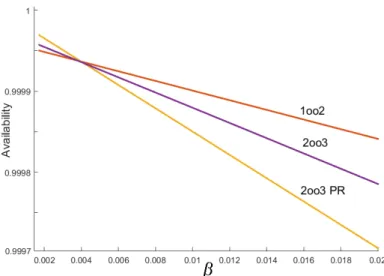
Reliability function, which is defined as probability of continuously staying oper-ational, is depicted in Figure 2.9 (refer to Table 2.1 for fixed parameter values). Despite high safety level, the 1oo2 suffers from high rate of false-trips (transitions into fail-safe state), even more than the simple 1oo1. This follows from the fact that total failure rate of 1oo2 is around 2λ, and any single DD failure brings whole system into fail-safe state. This is the cost paid for having high safety with a simple architecture. Moreover, note that if partial recovery is not provided, more complex 2oo3 system is not much better than the others. After first DD failure, 2oo3 degrades to 1oo2 where reliability drops sharply even less than 1oo1. With partial recovery, the faulty PE with DD failure is quickly recovered largely reducing the probability of having two consecutive DD failures. Superiority of systems for operational availability at time=∞ (steady state availability), at very low β value (which is not practically achievable), is as expected (see Figure 2.10, refer to Table 2.1 for fixed parameter values). However, as CCF rate increases, their order is swapped. This is due to the fact that staying more in operational
states means higher probability of being exposed to DU CCFs and having a di-rect jump into unsafe state which takes considerable time to be recovered from. Nevertheless, availability values are almost same, except 1oo1 which is by far the lowest (1oo1 is not shown).
Figure 2.9: Reliability functions for base systems.
Figure 2.10: Steady state operational availability value for base systems
2.5.2 Safety Sensitivity Analysis
In this section, we show the effect of variation in each of aforementioned parame-ters around defined default value, over PFH value. Mathematically, the following experiments show the partial derivations, ∂P F H/∂p, where p is one of the safety parameters. SIL1-SIL4 safety levels are plotted by horizontal lines to show rela-tive safety position. By such illustration of safety, designer perceives the distance of current design state from desired safety level. Besides, we also show a few pairs of relevant parameters in 2D-space. At initial states of configurations specified by default parameters, 1oo1 marginally could not achieve SIL2, while the rest are in SIL3 region. As explained before, generally 1oo2 is the safer configuration, while 2oo3 has higher reliability.
Figure 2.11: Effect of λP E variation over safety.
Sensitivity to λP E:
Figure 2.11 shows how safety is affected by different λP E values. Plots are almost
linear in logy-logx plane with slope equal to one, which describe linear functions in y-x plane passing through the origin. In other words, P F H = K · λP E. This
is also understandable from Markov models, where most of the transition rates are linear function of λP E. Linearity implies that by just knowing the line slope
which is achievable by having a single (λP E, P F H) point, and without solving
can be tuned. For example, an order of magnitude (10X) improvement in λP E,
results in shifting up one safety level (e.g. from SIL3 to SIL4).
Sensitivity to β and β2:
β and β2 are the indicators of mutual and trilateral isolation among PEs. It is
a well-known fact that CCF failures have strong adverse effect on safety-critical systems. Figure 2.12 depicts how systems’ safety is affected by β variation (refer to Table 2.1 for fixed parameter values). 1oo1 is independent from β as expected. One can observe from this figure that, for default parameters, it is quite difficult to get SIL4 through β improvement. Because by questionnaire method for β estimation (described in IEC 61508-6 [2]), β can hardly be estimated to be below 1%. A noticeable observation here is that similar to λP E, plots are almost linear in
logy-logx plane. This linearity makes adjustment of safety by tuning β parameter easily, without needing to solve complicated mathematical models every time.
The β2 is defined as a number in [0, 1] range, expressing part of β which is
shared among all three PEs [1], where it is typically in 0.2-0.5 range. It is clear that 1oo1 and 1oo2 are independent from β2. For a fixed β value, increase in
β2 leads to a decrease in β2oo3 and an obvious improvement in PFH. Therefore,
to have a more meaningful analysis, instead of β, we fix the β2oo3. Figure 2.13
shows that the variation in β2 has almost no effect over PFH (refer to Table 2.1
for fixed parameter values). The reason is that in a 2oo3 system, any mutual or trilateral CCF failure leads to the same situation, fail-safe or unsafe state. This assumption has to be reminded from Section 2.4.1 that CCFs are symmetric. In fact, this parameter affects the systems such as 1oo3 (not discussed here) in which the mutual CCFs can not defeat the redundancy, but trilateral CCFs can. One good design practice in such systems is to avoid sharing common resources among all PEs, such as communication links or power supply lines.
Figure 2.12: Effect of β variation over safety.
Figure 2.13: Effect of β2 variation over safety.
Sensitivity to Cself test:
According to formulas in section 2.3.3, self-testing is assumed to be equally ef-fective for both CCFs and non-CCFs. As shown in Figure 2.14, variation in this parameter can significantly affect the safety (refer to Table 2.1 for fixed parameter values). For achieving SIL4 in the 1oo2 system, the Cself testhas to be increased by
2%, while in 2oo3, it is more difficult, where at least 6% improvement is required (default of Cself test = 0.9).
Figure 2.14: Effect of Cself test variation over safety.
Sensitivity to ki:
ki is a constant which specifies the efficiency of comparison among PEs for de-tecting independent failures. Comparison is expected to be more efficient against non-CCFs than CCFs (ki = 0 for 1oo1). In Figure 2.15, there is an unexpected
behavior as ki has almost no sensible (or very small) influence on safety (refer
to Table 2.1 for fixed parameter values). The main reason for such observation is the absolute dominance of CCFs in above systems. More precisely, any DU CCF takes the whole system into unsafe state. However, two consecutive DU independent failures have to occur to cause the same situation which is far less probable. This is translated to an order of magnitude less influence of non-CCFs over safety. As a result, these systems seem to be rather insensitive to ki.
One possible incorrect conclusion from this observation is to give up compari-son for independent failures. But the fallacy is that whether a failure is dependent or not is not distinguishable before detection. As we will see, kc still has
con-siderable effect on safety and as a result, comparison cannot be ignored. Since kc is usually as low as 0.1-0.4, a relaxed comparison mechanism that leads to ki
value as low as kc is completely acceptable. Because it is enough to just have a
Figure 2.15: Effect of ki variation over safety.
Sensitivity to kc:
kc is a constant which specifies the efficiency of comparison among PEs for de-tecting CCFs. In both 1oo2 and 2oo3 configurations, CCFs mostly have a larger negative influence when compared to independent failures. Because a single inde-pendent failure is tolerable in both cases. By the definition of CCF, comparison is not expected to be very efficient against CCFs (kc= 0 for 1oo1). Nevertheless,
experiments (as shown in Figure 2.16) show that kcstill has a considerable effect
over safety.
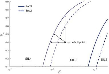
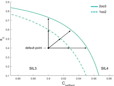
In case when one parameter is not sufficient to achieve the required safety level, simultaneous improvements on multiple parameters can be tried. Figures 2.17 and 2.18 show SIL regions in 2-D space while target safety is possible with values on SIL4 border lines (refer to Table 2.1 for fixed parameter values).
Figure 2.16: Effect of kc variation over safety.
Figure 2.17: Simultaneous improvement of β-factor and kc to reach SIL4
level.
Sensitivity to µOT:
Online repair which is invoked after online failure detection, is either employed when a single PE is not operational due to a DD failure (provided that partial recovery is available) or when DD failures are tolerated until whole system is in fail-safe state (if partial recovery is not provided). Effect of repair rate in the former (only applicable to 2oo3 with partial recovery) is negligible. Since such repair does not reduce the number of DU failures. In the latter, effect is
Figure 2.18: Simultaneous improvement of Cself test and kc to reach SIL4
level.
zero as expected (see Figure 2.19, refer to Table 2.1 for fixed parameter values.). Note that repairs from down states toward up states are not considered in PFH calculation (refer to Figure 2.5). In practice, this parameter is useful for adjusting reliability and availability.
Figure 2.19: Effect of online repair rate variation over safety.
Sensitivity to µP T:
Proof test and repair occurs periodically in long periods of time (at T I - test interval) to remove DU failures. It is either employed when whole system is in