This content has been downloaded from IOPscience. Please scroll down to see the full text.
Download details:
IP Address: 212.174.144.130
This content was downloaded on 06/07/2015 at 06:23
Please note that terms and conditions apply.
The ATLAS muon Micromegas R&D project: towards large-size chambers for the s-LHC
View the table of contents for this issue, or go to the journal homepage for more 2009 JINST 4 P12015
(http://iopscience.iop.org/1748-0221/4/12/P12015)
2009 JINST 4 P12015
PUBLISHED BYIOP PUBLISHING FORSISSARECEIVED: October 31, 2009 ACCEPTED: November 24, 2009 PUBLISHED: December 16, 2009
1st INTERNATIONAL CONFERENCE ON MICROPATTERN GASEOUS DETECTORS,
JUNE 12–15, 2009
KOLYMPARI, CRETE, GREECE
The ATLAS muon Micromegas R&D project: towards
large-size chambers for the s-LHC
T. Alexopoulos,aA.A. Altintas,b M. Alviggi,cM. Arik,bS.A. Cetin,d V. Chernyatine,e E. Cheu,f D. Della Volpe,c M. Dris,a D. Fassouliotis,g E.N. Gazis,aR. Giordano,c
V. Gratchev,h L. Guan,i P. Iengo,j P. Ioannou,gC. Li,i K. Johns,f V. Kaushik,f A. Khodinov,k C. Kourkoumelis,gS. Maltezos,a K. Mermigka,aH. M ¨uller,l
K. Nikolopoulos,g,e,1W. Park,mS. Persembe,bC. Petridou,nR. Petti,m
V. Polychronakos,eM.V. Purohit,mD. Sampsonidis,nG. Sekhniaidze,c M. Shao,i Y.J. Sun,i G. Tsipolitis,aR. Veenhof,o X.L. Wang,i J. Wotschack,l S.X. Wu,i T. Zhaop
and Z.G. Zhaoi
aNational Technical University of Athens,
Zografou Campus, Athens, 15780, Greece
bBogazici University of Istanbul,
Bebek/Istanbul, 34342, Turkey
cUniversity of Naples,
Naples, 80126, Italy
dDogus University of Istanbul,
Istanbul, 34722, Turkey
eBrookhaven National Laboratory,
Upton, NY 11973, U.S.A.
fUniversity of Arizona,
Tucson, AZ 85721, U.S.A.
gUniversity of Athens,
Ilissia, 15771, Greece
hPetersburg Nuclear Physics Institute,
Gatchina, 188350, Russia
iUniversity of Science and Technology of China,
An Hui, 230026, People’s Republic of China
2009 JINST 4 P12015
jLAPP, CNRS/IN2P3,
Annecy-le-Vieux, F-74941, France
kStony Brook University,
Stony Brook, NY 11794-3800, U.S.A.
lCERN,
Geneve, CH-1211, Switzerland
mUniversity of South Carolina,
Columbia, SC 29208, U.S.A. nUniversity of Thessaloniki, Thessaloniki, 54124, Greece oUniversity of Wisconsin, Madison, WI 53706-1481, U.S.A. pUniversity of Washington, Seattle, WA 98195, U.S.A. E-mail:[email protected]
ABSTRACT: Detectors based on the bulk-Micromegas technology exhibit position resolution better
than 100µm at counting rates of up to several tens of kHz/cm2, along with trigger capabilities.
These characteristics, combined with the detector’s mechanical robustness and the possibility for cost-effective industrial production, makes them a promising candidate for the ATLAS Muon Spec-trometer upgrade in a future luminosity enhancement of the LHC. The R&D project status will be presented together with the obtained results in the effort to define the baseline system specifications. KEYWORDS: Muon spectrometers; Micropattern gaseous detectors (MSGC, GEM, THGEM, RETHGEM, MICROMEGAS, InGrid, etc); Trigger detetectors; Particle tracking detectors (Gas-eous detectors)
2009 JINST 4 P12015
Contents
1 Introduction 1
2 The R&D project: muon ATLAS Micromegas activity 2
3 Medium-size prototype beam test 2008 3
4 Micromegas simulation 6
5 Micromegas asµ-TPC 8
6 Future directions 10
7 Summary 10
1 Introduction
The ATLAS detector [1,2] is designed to exploit the full physics potential of the Large Hadron
Col-lider (LHC) [3] which will provide pp collisions at√s= 14 TeV with an instantaneous luminosity
of 1034cm−2s−1. A major design consideration was the requirement for a Muon Spectrometer [4]
providing high quality stand-alone muon identification and momentum measurement, along with
trigger capabilities and extended pseudorapidity (η) coverage. To this end, a system of three
su-perconducting air-core toroids is employed in combination with high spatial resolution tracking chambers — Monitored Drift Tubes and Cathode Strip Chambers — and fast trigger detectors — Resistive Plate Chambers and Thin Gap Chambers. These detectors are able to sustain counting rates at least up to five times the expected rates at nominal LHC luminosity. The corresponding
counting rates are summarized in figure1.
For the future, an upgraded LHC — the super LHC (s-LHC) — delivering ten times higher instantaneous luminosity is being considered. This increase in luminosity would result in a roughly proportional increase of the expected counting rates from muons and background sources, namely photons, neutrons and protons. For the detector coverage and the good detector performance to be maintained under these conditions, it is likely that an upgrade of the present tracking and trigger
chambers in the forward region,|η| > 2, will be necessary. Specifically, this applies to the Inner
and Middle stations of the End-Cap Muon Spectrometer corresponding to a total surface of 400 m2.
The Micromegas (MICROMEsh GAseous Structure) detector [6,7] provides excellent
posi-tion resoluposi-tion and high counting rate performance, which can be combined with trigger
capa-bilities. The bulk-Micromegas technology [8] provides the possibility to produce mechanically
robust large-size detectors with cost-effective industrial processes. Thus, the bulk-Micromegas is a promising candidate for the upgrade of the ATLAS Muon Spectrometer at the s-LHC.
2009 JINST 4 P12015
Figure 1. Average single plane counting rates in Hz/cm2at the nominal LHC luminosity, 1034cm−2s−1, in the various parts of the Muon Spectrometer, from [5].
2 The R&D project: muon ATLAS Micromegas activity
The currently available estimates of the expected counting rates are plagued with large uncertain-ties and thus a solid definition of the performance requirements for the s-LHC is not possible. This situation will improve as soon as the LHC provides us with its first collisions, and the counting rates owing to muons and background will be measured. Nevertheless, using the currently avail-able information, a set of performance requirements serving as guideline to the R&D effort has been established:
• High counting rate capability, > 20 kHz/cm2, including dense ionization
• High single plane detection efficiency, & 98%
• Good spatial resolution, ≈ 100µm, possibly up to large incident angles, < 45o
• Second coordinate measurement
• Two-track separation at distance of ≈ 1–2 mm
• Good time resolution, ≈ 5 ns, to allow bunch crossing identification • Level-1 triggering capability
• Good aging properties
These detector requirements should be coupled with appropriate read-out electronics which will be able to cope with trigger rates of the order of 100 kHz, providing good pulse amplitude and timing measurements. Moreover, the limited bandwidth of the read-out link requires on-board zero-suppression functionality. For reliable operation in the harsh radiation environment of ATLAS radiation hardness and high single-event-upset tolerance are of primary importance.
2009 JINST 4 P12015
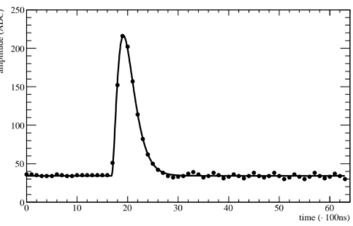
100ns) ⋅ time ( 0 10 20 30 40 50 60 amplitude (ADC) 0 50 100 150 200 250Figure 2. Electronics response for aδ pulse, sampled every 100 ns. The solid line is a fit to the design shaper response. One ADC count corresponds roughly to 900 electrons.
Although Micromegas detectors have been in wide use already for over a decade, they have not yet operated in colliding beam experiment. The Muon ATLAS Micromegas R&D project has been launched in 2007 aiming to use the bulk-Micromegas technology to produce large-size chambers
(about 1 m× 2 m) complying with the above mentioned requirements.
3 Medium-size prototype beam test 2008
In 2007 a medium-size bulk-Micromegas with an active area of 450 mm× 350 mm was produced
by CERN/EN-ICE. At the time of its production, it was one of the largest bulk-Micromegas ever
built. The mesh was formed by woven stainless steel wires arranged at a pitch of 78µm. The wire
diameter was 25µm. The amplification gap was 128µm thick, while the drift gap was adjusted to
5 mm. The copper read-out electrodes where shaped in strips and arranged in groups with different
pitch — 250, 500, 1000 and 2000µm — and length — 450 and 225 mm. The conditioning of the
chamber took place at CERN and its performance was first studied using an55Fe radioactive source.
A detailed description of the chamber construction and preliminary tests can be found in [9].
The prototype chamber was then exposed to 120 GeV pions at the CERN H6 beam line during the summer of 2008. 32 strips of the prototype were connected to charge sensitive preamplifiers
(CSP) with a voltage/charge conversion of 2 mV/fC, followed by electronics cards [10] with shapers
of 200 ns peaking time and with a signal gain of 3.7 in the high gain channels and 0.23 in the corresponding low gain channels. The CSPs were efficiently spark protected via cross-coupled
diodes and capacitive coupling. The shaper signals were digitized by 10 bit ALTRO chips [11] at a
sampling frequency of 10 MHz with a trigger pipeline of 16 events and 64 samples per event. The
data were recorded by the DATE system [12]. An example of the output signal for a single channel
is presented in figure2.
The experimental set-up is presented in figure 3. The beam entered from the back of the
photograph, passed through the Micromegas and subsequently through the set-up of scintillators and Si detectors. The trigger was defined by the coincidence of scintillators 1 and 2. Beam halo events were rejected by a third scintillator with a 3 cm diameter hole at the beam position used as
2009 JINST 4 P12015
Figure 3. The 2008 beam test set-up. The Micromegas prototype, the Si telescope modules and the trigger
scintillators are indicated.
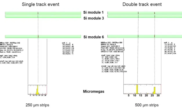
Figure 4. Event displays from the 2008 beam test. On the left, a single track, and on the right, a double
track event is presented.
silicon Module 1. An external reference measurement on the plane normal to the beam direction
was given by a telescope consisting of three modules of silicon strip detectors [13]. The point
resolution of each module was estimated to be 7.7µm.
During the beam test, three different gas mixtures were used — Ar:CO2:iC4H10 (88:10:2),
Ar:CF4:iC4H10 (88:10:2) and Ar:CF4:iC4H10 (95:3:2) — and data where collected with different
strip pitches and incident track angles. In figure4(left) a display of a single track event is presented.
The hits on the telescope modules are depicted at the upper part of the figure. At the lower part of the figure, the signals on the 32 strips of the Micromegas are presented. The strip pitch used is
2009 JINST 4 P12015
Cluster Charge (ADC counts)
0 500 1000 1500 2000 2500 3000 3500 4000 Cluster/(20 ADC) 0 20 40 60 80 100 120 140 160 180 200
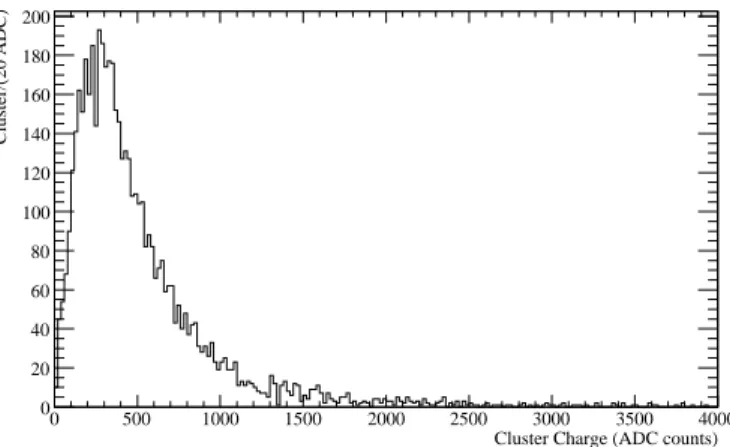
Figure 5. Cluster charge distribution for pions of 120 GeV in Ar:CF4:iC4H10(88:10:2). The amplification field was 37 kV/cm, while the drift field was 220 V/cm.
250µm. The formation of a charge cluster, with most of the charge being collected in two strips,
is visible. On the right part of figure4, the corresponding display for an event with two tracks
on 500µm strips is shown. In figure5, the distribution of the total cluster charge is presented for
Ar:CF4:iC4H10(88:10:2).
The position of the particle is reconstructed by charge interpolation in the cluster. The width
of the charge distribution was found to be ≈ 280µm full-width at half-maximum. The spatial
resolution is determined from the difference between the position measured in the Micromegas and the extrapolation of the telescope track to the Micromegas. The width of this distribution is affected by two contributions a) the intrinsic Micromegas resolution; and b) the uncertainty of the track extrapolation. The latter is due to the intrinsic resolution of the telescope and the multiple scattering in the trigger scintillators located between the Micromegas detector and the telescope.
It was estimated to be(61 ± 2)µm, where the attributed uncertainty is systematic arising from the
imprecise knowledge of the amount of material in the scintillators.
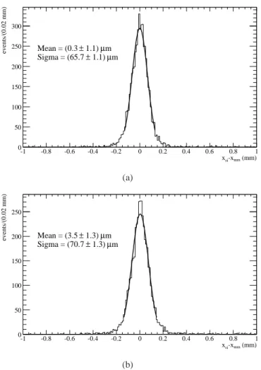
In figure6(a) and6(b), the corresponding distributions are presented for a Micromegas strip
pitch of 250µm and 500µm respectively, for normal incidence. The estimated spatial resolution
of the Micromegas detector,σMicromegas, is:
σMicromegas = (24 ± 7)µm for 250µm strip pitch
σMicromegas = (36 ± 5)µm for 500µm strip pitch
The relative uncertainties in these estimates are 30% and 15% for 250 and 500µm strip widths
respectively and, moreover, they are correlated in the two measurements. This is due to the dom-inance of the reference measurement extrapolation uncertainty on the width of the difference be-tween the Micromegas and the reference position measurement. The accuracy of the extrapolation uncertainty estimate in the set-up is defined by the knowledge of the amount of material between the silicon telescope and the Micromegas, which is only known at the 10% level. Although every effort to account for this oversight has been made, the magnitude and the nature of the uncertainty makes the above quoted resolutions more an order of magnitude estimate rather than a precise characterisation of the chamber performance.
The corresponding hit reconstruction efficiency, was estimated to be≈ 99%. The observed
2009 JINST 4 P12015
(mm) mm -x si x -1 -0.8 -0.6 -0.4 -0.2 0 0.2 0.4 0.6 0.8 1 events/(0.02 mm) 0 50 100 150 200 250 300 m µ 1.1) ± Mean = (0.3 m µ 1.1) ± Sigma = (65.7 (a) (mm) mm -x si x -1 -0.8 -0.6 -0.4 -0.2 0 0.2 0.4 0.6 0.8 1 events/(0.02 mm) 0 50 100 150 200 250 m µ 1.3) ± Mean = (3.5 m µ 1.3) ± Sigma = (70.7 (b)Figure 6. Difference between the position measured by the Micromegas and the extrapolated telescope
track, for (a) 250µm and (b) 500µm strip pitch.
4 Micromegas simulation
In order to improve the understanding of the beam test results, to ease performance studies for different operation parameters choice and to evaluate the potential of new ideas, it was deemed useful to develop a simulation of the detector, starting from the microscopic processes in the gas up to the output of the electronics.
For the development of this simulation suite established simulation codes have been used as
much as possible. The drift part is handled by GARFIELD [14] which interfaces HEED [15] for
the modeling of ionization processes in the gas and Magboltz [16] for the transport properties of
the drifting electrons. The amplification and electronics part is handled by custom code, which
uses a semi-analytical method for the ion induced charge calculation [17]. The simulation has been
configured to resemble the beam test set-up.
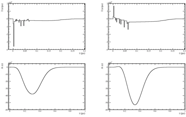
In figure7, a simulated event is shown for a strip width of 500µm and a drift gap of 5 mm.
For clarity only the central strip (right) and its neighbour with the highest charge (left) are shown.
2009 JINST 4 P12015
s) µ t ( 0 0.05 0.1 0.15 0.2 0.25 0.3 s) µ I (e/ -4 -3 -2 -1 0 1 2 6 10 × s) µ t ( 0 0.05 0.1 0.15 0.2 0.25 0.3 s) µ I (e/ -4 -3 -2 -1 0 1 2 6 10 × s) µ t ( 0 0.2 0.4 0.6 0.8 1 A (e) -60 -50 -40 -30 -20 -10 0 3 10 × s) µ t ( 0 0.2 0.4 0.6 0.8 1 A (e) -60 -50 -40 -30 -20 -10 0 3 10 ×Figure 7. A simulated event for a strip width of 500µm. Only the central (right) and the neighbour strip with the largest charge (left) are presented. On the upper row, the current developed in the amplification gap is depicted. In the lower row, the shaper output is presented. Note the different time scales in the two rows.
In the upper row, the current developed in the amplification gap is presented as a function of time. The spikes correspond to the arrival of the electron clusters. It can be seen that several electrons are collected in the neighbouring strip indicating that the track passed near the boundary of the two strips. The long current tail induced by the ion drift is also clearly visible. In the lower row the shaper output is presented.
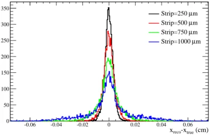
In figure8, the difference between the reconstructed and the true position of the simulated track
is presented for four different strip sizes. The performance deteriorates with increasing strip width and non-gauss tails are observed. It should be noted that the events in the tails are mainly cases where the incident particle passed through the center of the strip. In these cases, due to the large strip width, not enough charge for reliable interpolation is deposited in the neighbouring strips.
In figure9, the spatial resolution obtained from the beam test data and the simulation is directly
compared and found to be in good agreement. It is reminded, section3, that the uncertainties on
the experimental measurements are correlated.
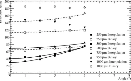
The dependence of the position resolution on the incidence angle is shown in figure10. Four
different strip widths are used, along with two different reconstruction algorithms: charge inter-polation and binary read-out. In the latter, the geometrical mean of the strips exceeding a certain threshold — in this particular case 5 times the electronic noise — is used. The charge interpolation method provides superior results for small incidence angles, while the binary read-out method is found to be more stable. The improvement in position resolution with increasing incidence angle
observed for the charge interpolation at 1000µm strip width could be attributed to better charge
sharing, exactly due to the track inclination, which resolves the left-right ambiguity for tracks pass-ing near the center of the strip.
2009 JINST 4 P12015
(cm) true -x reco x -0.06 -0.04 -0.02 0 0.02 0.04 0.06 0 50 100 150 200 250 300 350 m µ Strip=250 m µ Strip=500 m µ Strip=750 m µ Strip=1000Figure 8. Simulated residual distribution for uniform illumination and different strip widths.
m) µ Strip Width ( 100 200 300 400 500 600 700 800 900 m) µ Position Resolution ( 0 10 20 30 40 50 60 70 80
Beam Test Data Simulation
Figure 9. Measured and simulated position resolution for the 2008 beam test as a function of the strip width.
The uncertainties attributed to the different experimental points are correlated.
5 Micromegas as
µ
-TPCTo overcome the dependence of the position resolution on the incidence angle [18] several strategies
could be followed. In case enough space is available, one could tilt the chambers in order to
minimize the mean incidence angle [19]. Alternatively, the gas gap width could be decreased to
the absolutely operational minimum, albeit with possible effect on the reconstruction efficiency.
Another method would be to use the Micromegas as a — micro — Time Projection Chamber (µ
-TPC) where the few millimeter drift gap plays the role of the drift volume in a traditional TPC.
The principle of operation of theµ-TPC [20,21] is presented in figure11. The arrival time
of the ionization clusters on the strips can be used to reconstruct the trajectory, slope and intercept, of the track in the drift gap. The longer the projection of the path length, the more effective this approach will be for a given strip width. The reconstruction of the local track direction can be advantageous for pattern recognition, even at the trigger level.
2009 JINST 4 P12015
) ° Angle ( 0 1 2 3 4 5 6 7 8 m) µ Resolution ( 0 20 40 60 80 100 120 140 160 180 200 m Interpolation µ 250 m Binary µ 250 m Interpolation µ 500 m Binary µ 500 m Interpolation µ 750 m Binary µ 750 m Interpolation µ 1000 m Binary µ 1000Figure 10. Spatial resolution for charge interpolation and binary read-out as a function of the incidence
angle and strip width. The lines, where available, are fits to the formulaσ =σ0⊕σθtanθ, whereσ0the resolution for perpendicular tracks,θthe incidence angle andσθa parameter related to the properties of the sensitive material [18].
Figure 11. Principle of operation of the µ-TPC. The dotted arrow denotes the incident muon track, the crosses on the track path are the ionization clusters and the yellow lines are the drift paths of the individual electrons.
One of the major factors for the successful application of theµ-TPC method is the time
reso-lution, which should be of the order of few ns. In the 2008 beam test data, the long integration time of the preamplifier and the jitter of the trigger with respect to the ALTRO clock, did not permit an in-depth study of this method. However, an exploratory study has been pursued: The drift time
2009 JINST 4 P12015
information for each strip was extracted from the peak time of the signal pulse. The earliest peak time was used as the timing reference. By converting these drift times to drift distances, measure-ment points were formed subsequently fitted to a line. One significant source of uncertainty is the fluctuations in the spatial distribution of the primary ionization clusters along the track path. Addi-tionally, electrons drifting longer will be more affected by diffusion. From the available data it is
suggested that for a gas gap of 5 mm and a strip pitch of 500µm, the direction of a track inclined
by 35ocould be measured with 11% resolution.
Theµ-TPC method is a very interesting approach to overcome the angle dependence of the
position resolution. At the same time it is a very challenging one, since the requirements for the
µ-TPC method are almost perpendicular to those for charge interpolation methods.
6 Future directions
During the summer of 2009, a half-size prototype with active area 400 mm× 1300 mm was under
preparation at CERN, by CERN/EN-ICE. It will be equipped with a calendered mesh of
stainless-steel wires. The pitch of the wires is 56.4µm, while their diameter is 18µm. The amplification
gap is 128µm and the mesh is segmented into six parts. Two strip widths were selected, 250 and
500µm, while the length of the strips is 350 and 800 mm. It will be conditioned and characterised
with laboratory tests as soon as it becomes available and it will be tested in one of the forthcoming beam test periods.
The parallel plate geometry of the Micromegas detector makes it susceptible to discharges. Given the abundance of neutrons and photons in the ATLAS environment, it is very important to minimize the dead-time of the chamber and keep it at acceptable levels. Currently, two main approaches to resolve this issue are followed: a) use resistive coating on the read-out strips; and b) double stage amplification. In order to assess the severity of this issue, and the effectiveness of the suggested solutions, irradiation tests in neutron facilities using smaller size chambers will be performed.
As soon as the materials to be used for the chamber construction are defined, extensive ageing tests will be performed to ensure the good operation of the chamber in the harsh environment of the LHC.
7 Summary
The ten-fold luminosity increase in the s-LHC will require an upgrade of the ATLAS Muon Spec-trometer in order to maintain its good performance. The use of bulk-Micromegas for this upgrade is proposed and a dedicated R&D programme with this aim was launched in 2007. A medium-size prototype has been prepared and tested in a pion beam showing good performance in terms of op-eration stability, gas amplification, efficiency and spatial resolution for perpendicular tracks. Sim-ulation software that will ease performance studies has been developed and its results were found in agreement with the beam test data. Interesting approaches to overcome the angle dependence of the position resolution and the discharge rate are being pursued. The R&D activity is on-going
with the construction of a half-size detector (400 mm× 1300 mm), gas mixture optimization and
detailed studies of the detector performance — for example the time resolution.
2009 JINST 4 P12015
Acknowledgments
The authors would like to thank the staff of the CERN/EN-ICE workshop for producing various bulk-Micromegas for this R&D project and the colleagues from CEA-Saclay for the numerous discussions which have contributed to an improved understanding of several aspects of the con-struction and operation of Micromegas detectors.
References
[1] ATLAS collaboration, ATLAS detector and physics performance: technical design report, 1, CERN-LHCC-99-014(1999); ATLAS detector and physics performance: technical design report, 2, CERN-LHCC-99-015(1999).
[2] ATLAS collaboration, G. Aad et al., The ATLAS Experiment at the CERN Large Hadron Collider, 2008 JINST 3 S08003.
[3] O. Br¨uning et al., LHC design report. I. The LHC main ring,CERN-2004-003-V-1(2004). [4] ATLAS collaboration, A. Airapetian et al., ATLAS muon spectrometer: technical design report,
CERN-LHCC-97-022(1997).
[5] S. Baranov et al., Estimation of Radiation Background, Impact on Detectors, Activation and Shielding
Optimization in ATLAS,CERN-ATL-GEN-2005-001(2005).
[6] Y. Giomataris, P. Rebourgeard, J.P. Robert and G. Charpak, MICROMEGAS: a high-granularity
position-sensitive gaseous detector for high particle-flux environments,
Nucl. Instrum. Meth. A 376 (1996) 29.
[7] G. Barouch et al., Development of a fast gaseous detector “Micromegas”, Nucl. Instrum. Meth. A 423 (1999) 32.
[8] I. Giomataris et al., Micromegas in a bulk,Nucl. Instrum. Meth. A 560 (2006) 405 [physics/0501003].
[9] H. M¨uller et al., Development of muon chambers based on Micromegas technology for the upgrade of
the ATLAS experiment for the SLHC, submitted to IEEE Trans. Nucl. Sci..
[10] ALICE collaboration, H. M¨uller et al., Configurable electronics with low noise and 14-bit dynamic
range for photodiode-based photon detectors,Nucl. Instrum. Meth. A 565 (2006) 768.
[11] R. Esteve Bosch, A. Jimenez de Parga, B. Mota and L. Musa, The ALTRO chip: a 16-channel A/D
converter and digital processor for gas detectors,IEEE Trans. Nucl. Sci. 50 (2003) 2460. [12] ALICE collaboration, C.W. Fabjan et al., ALICE trigger data-acquisition high-level trigger and
control system: technical design report,CERN-LHCC-2003-062(2004).
[13] J. Treis et al., A modular PC based silicon microstrip beam telescope with high speed data
acquisition,Nucl. Instrum. Meth. A 490 (2002) 112[physics/0210004].
[14] R. Veenhof, GARFIELD, recent developments,Nucl. Instrum. Meth. A 419 (1998) 726. [15] I.B. Smirnov, Modeling of ionization produced by fast charged particles in gases,
Nucl. Instrum. Meth. A 554 (2005) 474.
[16] S.F. Biagi, Monte Carlo simulation of electron drift and diffusion in counting gases under the
2009 JINST 4 P12015
[17] E. Mathieson and G.C. Smith, Charge distributions in parallel plate avalanche chambers,Nucl. Instrum. Meth. A 273 (1988) 518.
[18] P. Rehak and E. Gatti, Semiconductor detectors in nuclear and particle physics, AIP Conf. Proc. 338 (1995) 319.
[19] T. Argyropoulos et al., Cathode strip chambers in ATLAS: installation, commissioning and in situ
performance,IEEE Trans. Nucl. Sci. 56 (2009) 1568.
[20] T. Bressani, G. Charpak, D. Rahm and ˘C. Zupan˘ci˘c, Track localization by means of a drift chamber, in proceedings of Dubna Meeting on Filmless and Streamer Chambers, Dubna Russia, April 15–18 1969. [21] B. Peyaud, KABES: a novel beam spectrometer for NA48,Nucl. Instrum. Meth. A 535 (2004) 247.
![Figure 1. Average single plane counting rates in Hz/cm 2 at the nominal LHC luminosity, 10 34 cm −2 s −1 , in the various parts of the Muon Spectrometer, from [ 5 ].](https://thumb-eu.123doks.com/thumbv2/9libnet/4041087.56779/5.892.257.650.126.411/figure-average-single-counting-nominal-luminosity-various-spectrometer.webp)