MSMW’04 Symposium Proceedings. Kharkov, Ukraine, June 21-26, 2004
RESONANCE LENS ANTENNA ANALYSIS FOR MM-WAVE APPLICATIONS
A.V. Boriskin’, A.I. Nosich’,’, S.V. Boriskina’, P. Sewell’, T.M. Benson2, A. Altintas3’
Institute of Radio-Physics and Electronics NASU, ul. Proskury 12, Kharkov 61085, Ukraine.’
G. Green Institute for Electromagnetic Research, University of Nottingham, NG7 2RD, UK Bilkent University, Ankara, 06533 Turkey. Email: [email protected]We report what is to our knowledge the first accurate theoretical investigation of the electromagnetic behavior of 2-D elliptical lenses of finite wavelength-scale size. The role of internal resonances in the focal domain formation is studied. A proposal of a narrow-band receiver based on a hemielliptic lens tuned to a resonance is discussed. Possible features of such a lens-coupled receiver are stability of the resonance field with respect to the angle of arrival of incident wave and several times greater values of the peak field intensity that may potentially lead to higher sensitivity and better scanning performance.
In the analysis, we use the Muller boundary integral equation (BIE) technique. This full-wave mathematically rigorous method is combined with trigonometric Galerkin discretization to result in the efficient numerical solution for an arbitrary set of the electrical, geometrical, and material parameters.
Numerical results are generated for a quartz elliptical lens ( E = 3.8) with dimensions typical to mm-wave
radar applications [I]. Near field analysis, lens-focusing properties and lens frequency-dependent performance are presented.
Introduction.
Printed slot or strip elements combined with dielectric lenses are frequently met components of
mm
and sub-mm wave receivers [2]-[6]. The attention they have been attracting recently is due to their capability of compact integration with other electronic components such as detecting diodes, local oscillators and mixers. Besides, they provide better efficiency than other types ofantennas printed on homogeneous substrates. The elliptical shape of the lens is borrowed from optics to provide focusing properties if its eccentricity is selected properly. On the other hand, the lens interface gives rise to reflections inside a realistic lens that may significantly affect the input impedance and sensitivity. This aspect, which has not been properly investigated in the literature, is a critical point in the overall design of lens antennas [3], [ 6 ] . Various analytical techniques used to simulate dielectric lenses have been commonly based on the ray-tracing, neglected the lens size and curvature and hence failed to characterize the internal resonances. The validity of such approximations can in many cases be questionable as the actual size of the lens is several wavelengths [2]-[7]. In fact, a behavior of such a lens should clearly display both ray-like and resonance-mode features. On the other hand, direct numerical simulators like FDTD-based ones are extremely time and memory consuming, require
1. and notations Of an extended
are for the ray-
~~~~~~~s~~&~.~d
-20 -15 -10 -5 0 5 10 15 20
Figure 2. The near-filed intensity portraits for the elliptic lens (a) and extended hemielliptic lenses with 2, corresponding to the geometrical focus location (b) and the nearest resonance (c). Dotted lines denote the far geometrical focus location. E-polarization, y= 0, E = 3.8, ka = 16, Z2 =1,165.
0-7803-841 I -3/04/$20.0002004 IEEE
MSMW’O4 Symposium Proceedings. Kharkov, Ukraine, June 21-26, 2004
accurate treatment of the back-reflections from the edge of the computational window, and may suffer from a loss of accuracy. All the above shows that the true electro-magnetic be-havior of dielectric lenses is still far from being clear.
Outline of the solution.
A brief outline of analysis method is as follows. In 2-D, the focusing properties study can be formulated as a problem of the plane wave scattering by a smooth dielectric cylinder. The application of the Green’s identity enables one to express the fields inside and outside the lens versus the values of fields and their normal derivatives at cylinder’s contour. By applying the boundary conditions, a set of the Fredholm second kind IEs is obtained, known as Muller’s boundary E s [8]. Further we discretize them by applying the Galerkin method with entire- domain angular exponents as expansion functions. To treat the (integrable) singularities in some of the kernel hnctions, we use analytical integration of the canonical circular-cylinder counterpart terms.
This procedure results in a Fredholm second kind infinite-matrix equation having favorable features, with matrix elements and right-hand-part terms obtained as Fourier- expansion coefficients of some twice-continuous functions. They can be economically computed by using the DFFT and FFT algorithms, respectively. Developed algorithm guarantees point-wise convergence of the numerical solution, i.e., a possibility to minimize the error to the level set by the DFFT if solving progressively greater matrices. Note that required accuracy can be achieved for an arbitrary set of the lens parameters, e.g., for any value of the contrast between the lens material and the background medium. It is also free from the inaccuracies near to the sharp natural resonances that is intrinsic to conventional numerical approximations [9], as well as from the well-known defect of “numerical resonances” occurring if the fields are presented as single or double layer potentials [ 101.
More solution details and algorithm properties can be found in [ll]. The advantages of the method outlined above make it efficient CAD tool, which can be applied to the accurate analysis of dielectric lenses in the wide range of frequencies and geometries.
Numerical results.
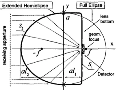
We shall simulate the cross-sectional contour of the truncated elliptic lens with a curve S, which is twice- differentiable at every point and consists of two open curves
SI,
S, smoothly joined together at the points marked with crosses (Fig.1). Here,
Sz
is a half of the ellipse with eccentricitye=l/& and
SI
is a half of so-called “super-ellipse” that simulates a rectangle with rounded corners.In the Fig. 2 the near-filed intensity portraits for the extended hemielliptical lens with I l corresponding to the geometrical focus location and the first resonance revealed in Fig. 3 are shown. It is seen that the ellipse truncation leads to a dramatic change in the field distribution inside the lens and
03 0,6 0.7 0,8 0,9 1 ,o
Figure 3. Focusability of the lens along x- and y-
axis versus the parameter characterizing the extension of the lens rear side.
Figure 4. The overall peak field intensity and that on the lens bottom versus the rear side extension parameter.
2
4 j
003 0,6 0.7 0,8 0.9 1 ,o
Figure 5 . The distance between the point with the highest intensity and the lens bottom.
Figure 6. The peak field intensity versus the normalized frequency parameter for the quasi- optical and the resonant lenses.
a noticeable increase of the peak intensity, Moreover, while the field intensity portrait for the lens extended to the geometrical focus resemble a ray-tracing picture (here and after quasi-optical lens), similar portrait for the lens extended to the nearest internal resonance
MSMW’04 Symposium Proceedings. Kharkov, Ukraine, June 21-26, 2004
(here and after resonant lens) clearly shows additional intensive field spots. Such resonance resembles, to some extent, asymptotic GO resonances known as “billiard-type” ones. Here they have specific triangular portraits and can be classified by two indices, which indicate the variations of the field along the lens flat side (m) and a side of the triangle (n). Two neighboring resonances in 1, have n and n +1 variations with apparently the same m, and the distance between them corresponds to half a wavelength in dielectric along the triangle side.
The ability of the lens to focus the radiation along the x- and y-axes can be quantified by the “focusability parameters” defined as
F,
= d ( x , , ym)l(zm,
where z = x , y ( x m Y y m ) are the coordinates of the highest field intensity point ( I = IE,1’
) inside the lens, and ( x ~ , ~,
y o , 5 ) are the coordinates of the half maximum intensity values.Analysis of graphs presented in Fig. 3 and Fig. 4 shows that the focal spot size is stable for the considered vales of
I , .
Internal resonances result in both focusability and peak intensity increase. Fig. 5 shows that the focal domain is always shifted inside the lens but located at the fixed distance from the lens bottom for a wide range of values of I , . Besides, as it is seen from Fig. 4, the field intensity at the lens bottom is only a half its value in focal point. These facts are important as they suggest one to locate the detectors inside the lens instead of typical lens-coupled antenna design in which a lens is glued over a slot antenna.Analysis shows that such a resonant lens tuned for the internal resonance has certain advanced properties, despite loosing its wideband nature, namely stability of the resonance field with respect to the angle of arrival of incident wave and several times greater values of the peak intensity. Narrow-band receiver exploiting this effect may potentially have improved sensitivity and scanning performance.
The frequency dependences of the peak intensity for quasi-optical and resonant lenses (Fig. 6) show that both types of lenses have internal resonances, which result in narrow peak intensity flashes. This fact has two outcomes. One is that any finite size lens focusing properties are frequency-dependent, Another is that for a wide-band applications the only requirement for the lens extension size is to be in a range of 0.55-0.8 in order to
keep the focal domain close to the lens
bottom
because the presence of internal resonances will similarly affect any lens focusing characteristics with a bottom extension in the given range.Summary.
The electromagnetic behavior of extended hemi-elliptical lens has been studied. The most important feature revealed by the accurate analysis is that the resonances may play a dominant role in the wavelength-scale lens behavior. Obtained results show that advanced characteristics of the lens-coupled receiver can be achieved, although in a narrow band, by exploiting a resonance.
1. 2. 3. 4. 5. 6. 7. 8. 9. References
D. Chouvaev, M. Danestig, ‘Slot antennas and quasioptical beamforming for a cast-efficient integrated automotive radar D.F. Filippovich, S.S. Gearhart, G.M. Rebeiz, ‘Double slot on extended hemispherical and elliptical silicon dielectric lenses’, IEEE Trans. Microwave Theory Techniques, vol. 41, no. 10, pp.1738-1749, 1993.
P.U. Jepsen, S.R. Keiding, ‘Radiation patterns from lens-coupled terahertz antennas’, Optics Letters, vol. 20, no. 8, pp. 807-809, Apr. 1995.
Neto, S. Maci, P.J.I. de Maagt, ‘Reflections inside an elliptical dielectric lens antenna’, IEE Proc.
-
Microwaves, Antennas, Propagation, vol. 145, no. 3, pp. 243-247, 1998.X. Wu, G.V. Eleftheriades, T.E. van Deventer-Perkins, “Design and characterization of single and multipie-beam mm-
wave circularly polarized substrate lens antennas for wireless communications”, IEEE Trans. Microwave Theory Techniques, vol. 49, no.3, pp. 431-441,2001.
J. Rudd, D. Mittleman, ‘Influence of substrate-lens design in terahertz time-domain spectroscopy’, J . Optical Sociew America B, vol. 19, no. 2, pp. 319-329,2002.
J. Rudd, J.I. Johnson, D. Mittleman, ‘Quadrupole radiation from terahertz dipole antennas’, Optics Letters, vol. 25, no.
20, pp. 1556-1558, Feb. 2000.
C. Muller, Foundations of the Mathematical Theory of Electromagnetic Waves, Springer, Berlin, 1969.
G.L. Hower, et al., ‘Inaccuracies in numerical calculations of scattering near natural frequencies of penetrable objects’, IEEE Trans. Antennas Propagation, vol. AP-41, no 7, pp. 982-986, 1993.
10. S. Amini, S.M. Kirkup, ‘Solutions of Helmholtz equation in the exterior domain by elementary boundary integral methods’, J. Comput. Physics, vol. 118, pp.208-221, 1995.
11. S.V. Boriskina, T.M. Benson, P. Sewell, A.I. Nosich, ‘Accurate simulation of 2D optical microcavities with uniquely solvable boundary integral equations and trigonometric-Galerkin discretization’, J. Optical Soc. Am. A , vol. 21, no. 3, pp. 392402.2004.