0885–3010 © 2014 IEEE
Parametric Nonlinear Lumped Element
Model for Circular CMUTs
in Collapsed Mode
Elif aydoğdu, Student Member, IEEE, alper ozgurluk, Student Member, IEEE, abdullah atalar, Fellow, IEEE, and Hayrettin Köymen, Senior Member, IEEE
Abstract—We present a parametric equivalent circuit model for a circular CMUT in collapsed mode. First, we calculate the collapsed membrane deflection, utilizing the exact electri-cal force distribution in the analytielectri-cal formulation of mem-brane deflection. Then we develop a lumped element model of collapsed membrane operation. The radiation impedance for collapsed mode is also included in the model. The model is merged with the uncollapsed mode model to obtain a simula-tion tool that handles all CMUT behavior, in transmit or re-ceive. Large- and small-signal operation of a single CMUT can be fully simulated for any excitation regime. The results are in good agreement with FEM simulations.
I. Introduction
a
ccurate modeling of capacitive micromachined ul-trasonic transducers (cMUTs) is essential to reach a successful design without trial and error. Because a cMUT’s mechanical operation is distributed and nonlin-ear, its modeling is not straightforward. There have been several approaches reported in the literature. The most reliable, and very commonly used, method has been fi-nite element modeling (FEM) [1]–[3]. In the fifi-nite element analysis environment, the operation of a cMUT mem-brane can be simulated with high accuracy at the cost of extensive computation and time consumption. This com-putation cost forces researchers to use alternative methods for predicting cMUT operation. These methods include characterization of cMUT behavior using experimental observations [4]–[6], analytical calculation of the distrib-uted membrane bending and the electrical-mechanical energy transfer efficiency [7]–[10], and defining lumped elements to develop models suitable for dynamic simula-tions. Electrical circuit elements constitute a convenient basis for lumped element modeling. starting from Mason’s model for acoustic transducers [11], equivalent circuit modeling has been improving as a powerful alternative to FEM [9], [12]–[15], especially for array modeling [16]–[18]. The studies directed toward understanding and modeling mutual impedance of cMUT arrays [2], [4], [17], [19], [20]have helped to improve the accuracy of lumped element simulations.
cMUTs are commonly used in large arrays. The opera-tion of large cMUT arrays can only be predicted using lumped element modeling, because the computation cost of FEM exponentially increases with increasing cell count. currently, the uncollapsed-mode operation of cMUT ar-rays is well understood through equivalent circuit model simulations [17]. The mechanical and electrical properties of uncollapsed-mode operation are perfectly adapted to the lumped model [21].
on the other hand, the collapsed-mode operation has not been completely modeled so far, because it has not been possible to obtain an analytical expression for the collapsed membrane bending.
collapsed mode offers high coupling efficiency, as shown in [22]. In [23], it was observed that a cMUT can produce higher transmit power in collapsed mode than in uncollapsed mode. To explore this mode further, and per-form array simulations, it is necessary to obtain a lumped element model. an equivalent circuit model for collapsed mode was previously introduced in [24]; however, it was not a fully parametric model. numerical calculations of the bending profile of a specific cMUT design were adapt-ed to the model; hence, new numerical calculations had to be carried out for every new set of design parameters. also, the bending profile calculations were done utilizing Timoshenko’s [25] uniform force solution, and this unifor-mity approximation did not result in high accuracy.
In this work, a fully parametric model for a cMUT in collapsed mode is obtained. First, the collapsed mem-brane bending is calculated with high accuracy, utilizing the nonuniform electrostatic force expression in Timosh-enko’s equation instead of the uniform force approxima-tion. The calculations are then adapted to the lumped element model of [21]. We model the collapsed-mode op-eration of a single cMUT at FEM accuracy, including the self-radiation impedance of collapsed mode [26]. We also merge the model with the uncollapsed mode part given in [18] and obtain a single model for the entire large-signal operation of the cMUT.
II. calculation of Bending Profile in collapsed Mode
Fig. 1 shows a cMUT cell in the collapsed mode; Table I lists the description of relevant variables.
Manuscript received July 1, 2013; accepted september 18, 2013. This work was supported by the scientific and Technological research coun-cil of Turkey (TUBITaK) under project grant 110E216. a. atalar ac-knowledges the support of the Turkish academy of sciences (TUBa).
E. aydoğdu, a. atalar, and H. Köymen are with the Electrical and Electronics Engineering department, Bilkent University, ankara, Turkey (e-mail: [email protected]).
a. ozgurluk is with the Electrical Engineering and computer sciences department, University of california, Berkeley, Berkeley, ca.
A. Accurate Formulation of Deflection-Force Relation Timoshenko [25] provides the formulation for the bend-ing profile x(r) for a circularly symmetrical pressure dis-tribution P(r) on a circular plate as
r r r r r r x r D bP
r d
d 1dd dd ( ) = 1
∫
( )ξ ξ ξ,d (1)where r is the radial variable, and D = Etm3/12(1− υ .2)
a convenient approach for calculation of uncollapsed membrane bending is to approximate all forces with an equivalent uniform pressure distribution across the mem-brane. This way, x(r) can be expressed analytically and can also be used to obtain analytical expressions for lumped electrical force, capacitance, and mechanical compliance.
on the other hand, this uniform pressure approxima-tion does not yield accurate results for a collapsed mem-brane, because the electrical force distribution is highly nonuniform in collapsed mode. In previous studies [24], it was observed that the calculated contact radius turns out to be smaller than expected when the force distribution on the membrane is assumed to be uniform. In reality, the electrical force increases significantly close to the contact point because of the decreased gap, exerting a higher pull-ing force in this region compared with the periphery.
We utilize the real force distribution, which we call the model force, in Timoshenko’s equation:
r r r r r r x r D b P t Vx r b d d 1dd dd ( ) = 1 2(ge 0 ( 2 + −
∫
ε ξξ ξ ξ ))2 . d (2) Here, the pressure term P(r) is replaced with the electri-cal force density at every point on the membrane, added to the remaining uniformly distributed static pressure Pb. Pb accounts for the ambient atmospheric or hydrostatic pressure. tge is the effective gap height, with tge = tg + ti/εr, where tg is the gap height, ti is the insulator thick-ness, and εr is the relative dielectric permittivity of the insulator, as given in Table I. The electrical force densityis the electrostatic force on the unit area capacitor with a gap tge − x(r), having a voltage V across it.
There is no analytical solution for x(r) of (2). We first normalize the variables and rearrange (2) into the generic form r r r r r r x r b PP V V r b r d d dd dd g / 1 ( ) = 64 2( ) 9( 2
∫
+ 11− ( ))2 x ξ ξ ξd , (3) where the normalized variables arer = ,ar b = ,ab x() =⋅ xt()⋅ .
ge (4)
Pg is the pressure that corresponds to a peak membrane displacement of tge at zero bias (x(0) = 1), and Vr is the collapse voltage at vacuum [21]:
P Dt a V a Dt r g =64 4ge, = 3162 ge. 3 0 ε (5)
The boundary conditions of the differential equation in (3) can be written as x r x r r x r r x r r x r t t r r b r r b ( ) = 0, ( ) = , ( ) = 0, ( ) = 0, ( =1 = =1 = 2 2 g ge d d d d dd ))r b= = 0. (6)
The input parameters are V/Vr, Pb/Pg, and tg/tge. The
resulting b and x r( ) are calculated using the algorithm described in the next section.
B. Solution Algorithm
our strategy of solving (3) under the boundary condi-tions of (6) is expressing the force term in such a way that an analytical solution can be obtained. If the pressure term can be expressed as a Kth degree polynomial, as in
r r r r r r x r c b r n K n n d d 1dd dd ( ) = =1
∫ ∑
ξ dξ, (7) an analytical solution exists:E young’s modulus of membrane material
υ Poisson’s ratio of membrane material
ρ density of membrane material
D Flexural rigidity of membrane material
ρ0 density of immersion medium
x r r r r r r A A A A c n n n K n n ( ) = ( ) ( ) ( 1) ( 3) 1 2 2 3 4 2 =1 3 2 2 + + + + + + +
∑
+ log log rr r cnb n K n n 2 =1 1 (1−log( ))∑
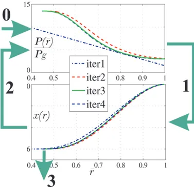
4( ++1), (8) where A1, A2, A3, and A4 are the constants of integration. We use (8) in our iterative solution routine as shown in Fig. 2 and as follows:0) Given the physical parameters, the normalized static force, and the excitation voltage, start with an initial guess of the pressure distribution. To enable faster convergence, the following linearly varying distribu-tion is used as the initial guess:1
P P P P V V t t r b r r ( )= 1.52( ) (1 ) 9(1 ) 2 2 g g g ge / / + − − .
1) a polynomial with coefficients cn (n = 0, 1, …, K) is
fitted to the pressure distribution. To achieve con-vergence in all cases, we set K = 14. substituting this polynomial into (7), an analytical expression for
x r( ) in (8) with five unknowns (A1, A2, A3, A4, and b) is obtained. The first four boundary conditions in (6) are solved with a symbolic math package to ex-press Ai in terms of b. Then, the last boundary
con-dition is used to determine b by finding the zero-crossing point.
2) Using the obtained bending profile, x r( ), the new pressure distribution is calculated through the
elec-trical force density expression in the right-hand side of (3): P P( )r =PPb 9(12(V Vx( ))r) 2 2 g g / + − ξ .
3) Go to step 1 and repeat until b converges to a value within 0.1% difference between successive itera-tions.
Plots for x r( ) calculations are given in Fig. 3, showing the difference between the bending profiles obtained with uniform pressure approximation, and model force with Pb = 0. There are four cases for a cMUT of tg/tge = 0.9. In the uncollapsed mode, close to the collapse point, where
xP = x(0) = 0.45 (normalized peak displacement), the two profiles are very similar. This means that the uniform pressure approximation can be used for predicting uncol-lapsed-mode operation. However, as the displacement in-creases and the membrane enters the unstable region, the profiles start to diverge from each other, as seen in the xP
= 0.7 plot. at the snapback point where the membrane barely touches bottom, and in the collapsed mode, the dif-ference is even larger. at snapback, the uniform pressure approximation gives V = 0.55Vr and xR = 0.402 (normal-ized rms displacement),2 whereas the model force results
in V = 0.58Vr and xR = 0.358. C. Results: Collapse and Snapback
The transduction force, capacitance, and compliance of a cMUT are determined by the deflection profile. The pro-file depends both on the normalized static pressure, which is uniformly distributed, and on the electrical force. In the model presented in this work, the effect of the profile is uniquely summarized in rms displacement. although one can have the same rms displacement for different combina-tions of normalized static ambient pressure and electrical force, for a given pair of Pb/Pg and tg/tge, electrical force
Fig. 2. demonstration of iterative algorithm for solving x r( ).
Fig. 3. normalized deflection profiles of uniform pressure-loaded (V = 0) and model force-loaded (Pb = 0) membranes with tg/tge = 0.9. Both
profiles have the same peak displacements (xP = 0.45 and 0.7) in
uncol-lapsed mode, and the same contact radius at snapback (b = 0) and in collapsed mode (b = 0.25).
1 The initial pressure should be sufficiently high to make the membrane
collapse. 2 This is defined by xR = 1 ( 2) 2 ( )
0 2 /πa ∫aπrx r rd.
and the model elements can be uniquely defined as func-tions of rms displacement.
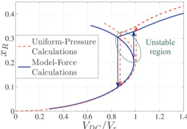
In Fig. 4, the normalized rms displacement (xR =
xR/tge) is plotted as a function of normalized bias voltage (V/Vr), similar to the cMUT biasing chart of [21]. The uncollapsed mode static analysis result for vacuum (Pb = 0), obtained with the uniform pressure approximation given in Fig. 5 of [21] is shown here with a dashed curve. The model force result shown in the plot (solid curve) is obtained also in vacuum, and the electrical force distribu-tion on the membrane is highly nonuniform in the unsta-ble region and in the collapsed region. results obtained with the uniform pressure approximation of electrical force considerably diverge from the model force results in these regions. This is the source of the error in the predic-tion of snapback voltage in [24].
The transition from the uncollapsed mode to the col-lapsed mode happens at a voltage level where the mem-brane quickly passes through the unstable region and reaches a new balance point in the collapsed region (up-ward arrow). The snapback transition from the collapsed mode (at zero contact radius) to the uncollapsed mode occurs at a lower voltage (downward arrow).
III. lumped Element Model of a single cMUT in collapsed Mode
The static calculations of collapsed membrane bending are used to define the elements in the lumped model of Fig. 5.
as seen from the electrical side, the cMUT behaves like a capacitor whose value depends on instantaneous membrane displacement. on the left side of Fig. 5, this is represented with C0, the undeflected membrane capaci-tance, and two current sources, iC and iV [21]
iC = (C−C0)dV tdt( ) (9)
membrane: the electrical force fR, the force resulting from
ambient pressure FRb, and the dynamic external force fRI.
The membrane exerts a restoring force determined by its compliance CRm. In the uncollapsed mode, the
compli-ance has a fixed value [21] of
C a Et Rm m 0 = 9(1 ) 80 . 2 2 2 − υ π (11)
The instantaneous values of C and CRm, and hence the
transduction force, are determined by the instantaneous rms displacement. The static and instantaneous values are the same for each of these lumped model elements and force.
Because the through variable in the model is chosen as rms velocity, the model inductance, which conserves the energy, is the mass of the membrane [18], [21], [24]:
LRm =πa t2 mρ. (12)
The dynamic lumped element model is completed by terminating the acoustic port by appropriate radiation im-pedance [25]. The radiation imim-pedance ZRR is dependent on the instantaneous contact radius, and consequently on rms displacement.
a large set of static bending calculations is obtained to define the lumped parameters’ dependence on xR, tg/tge, and Pb/Pg. For each bending profile solution, C is calcu-lated first and it is used to find fR and CRm.
static analysis solutions for x r( ) are obtained at seven different values of tg/tge = 0.4, 0.5, 0.6, 0.65, 0.73, 0.82, and 0.9, and interpolation can be done for intermediate values. When tg/tge is less than 0.4, the profile is the same as for uniform force distribution. When tg/tge is chosen larger than 0.9, the iterations do not converge; hence, the model is valid up to this value.
For each tg/tge value, Pb/Pg = 0, 0.2, 1, and 2 cases are analyzed, because the intermediate values can be
accu-Fig. 4. normalized displacement xR as a function of normalized applied
voltage Vdc/Vr in uncollapsed and collapsed modes for tg/tge = 0.73.
Fig. 5. The equivalent electrical circuit model of a cMUT with the through variable vR.
rately interpolated from the data obtained at those static pressure levels.
For each case, solutions are obtained at 50 values of (V/Vr) between the normalized snapback voltage (the voltage level at which the membrane exits collapse mode) and a large value, 10. Therefore, a total of 1400 normal-ized cases are analyzed. With each sweep of (V/Vr), keep-ing tg/tge and Pb/Pg fixed, we obtained curves of C, CRm, and b.
A. Capacitance
The capacitance C for a given deflection profile x r( ) is
C =C0 1 2rx r r( ) 0
1
∫
− d (13)C0 =ε π /0 a t2 ge. (14)
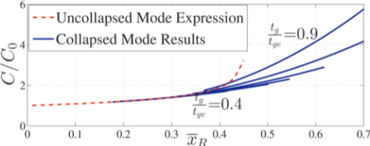
In Fig. 6, the calculated C/C0 values are plotted as a function of xR for different values of tg/tge. For demonstra-tion purposes, only the Pb/Pg = 0.2 case is given. When the membrane is uncollapsed, normalized capacitance is not affected by tg/tge. In collapsed mode, the membrane can approach the substrate more for larger values of tg/tge (thin insulator), and both the capacitance and the rms displacement can be comparatively large. as tg/tge de-creases (larger insulator thickness), both the displacement and the capacitance assume smaller values. The dashed line is the plot of uncollapsed mode capacitance calculated using the formula of uniform pressure approximation giv-en in the appgiv-endix. The collapsed mode calculations start with the snapback, so the initial points on solid lines cor-respond to the transition from collapsed mode to uncol-lapsed mode. However, those points do not coincide with the dashed plot because of the slight error caused by uni-form pressure approximation.
B. Electrical Force
The electrical force is the energy-conserving force, de-fined as
fR Exel V xC Vt xC
R R R
= dd = 22dd = 2 2 dd .
ge (15)
The d /dC xR term is introduced into the lumped model. With C/C0 data in hand, d /dC xR is numerically calcu-lated for all tg/tge and Pb/Pg. capacitance and capaci-tance derivative are defined as separate functions of xR for every Pb/Pg and tg/tge pair.3
C. Compliance
The compliance of the membrane is defined as the ratio of xR to the rms force on the membrane. In our deflection profile calculations, this force is the sum of the static elec-trical force FR and the static uniform force FRb:
CRm F xRF
R Rb
= + . (16)
normalized compliance CRm/CRm0 is plotted with re-spect to xR in Fig. 7 for different tg/tge values with Pb/Pg = 0. In the stable region of the uncollapsed mode, the membrane behaves like a linear spring of compliance CRm0.
In the unstable region of the uncollapsed mode, the com-pliance assumes higher values than CRm0. When the mem-brane comes in contact with the bottom layer (this is also the snapback point), the compliance decreases nonlinearly with increasing displacement. The membrane becomes stiffer at larger contact radii. The point of contact is de-termined by the thickness of insulator. For the tg/tge = 0.4 case, the insulator is so thick that the membrane touches the bottom layer without experiencing instability. on the other hand, for tg/tge = 0.9, there is a wide region of insta-bility at the end of which the compliance reaches a high value.
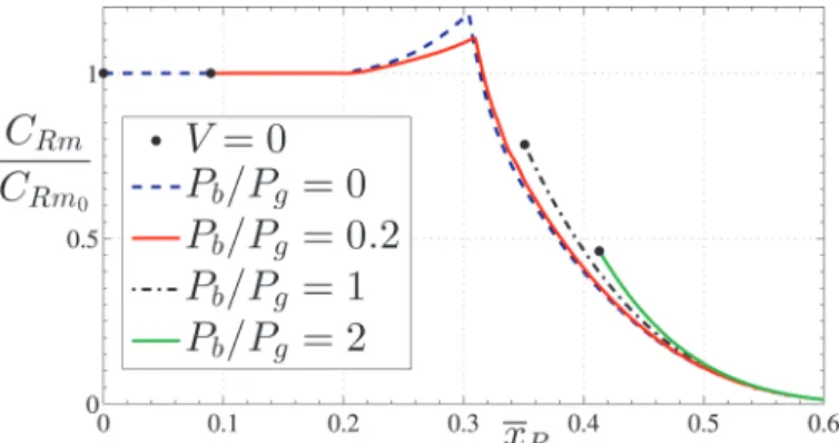
In Fig. 8, the normalized compliance is plotted for dif-ferent levels of ambient pressure Pb/Pg (the tg/tge = 0.73 case is shown). at vacuum, the membrane starts with zero deflection at V = 0, whereas there is an initial deflection for Pb/Pg = 0.2, 1 or 2. For Pb/Pg = 1 or 2, the ambient pressure is so large that the membrane touches bottom even at V = 0; hence it is always in collapse mode. For Pb/Pg = 2, the initial deflection is larger, and the initial compliance is correspondingly smaller. In the collapsed mode, the compliance at the same displacement turns out to be larger for higher ambient pressure.
D. Contact Radius
Fig. 9 shows the normalized contact radius, b, as a function of xR for two values of Pb/Pg and for different values of tg/tge. For Pb/Pg = 1, ambient pressure is strong enough to make the membrane touch the bottom layer
Fig. 6. normalized electrical capacitance as a function of normalized rms displacement. Pb/Pg = 0.2 and tg/tge = 0.4, 0.5, 0.6, 0.65, 0.73, 0.82,
and 0.9.
3 observing that the Pb/Pg dependencies of capacitance and
capaci-tance derivative are weak, it is possible to use the Pb/Pg = 0.2 data for
even at zero voltage, so the Pb/Pg = 1 plots start at
non-zero b values.
We observe significant differences between the solid and dashed plots of the tg/tge = 0.9 case. close to snapback,
they assume very different xR values at the same contact radius. This is because the bending profiles of uniform pressure-deflected and electrical force-deflected mem-branes are considerably different in collapsed mode.
To adapt all these calculations to the lumped model, polynomials are fitted to the numerical results of C( )xR/ ,C0
dC x( )R/dxR, CRm R( )x /CRm0, and b x( ).R The polynomial coefficients are given in the appendix.
E. Self-Radiation Impedance in Collapsed Mode
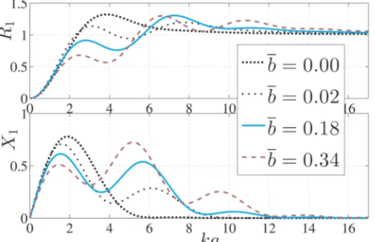
The interaction between the cMUT membrane and the radiation medium is determined by the velocity profile of the membrane. In uncollapsed mode, the entire membrane surface is active, whereas the periphery beyond the con-tact point is the active region in collapsed mode. The radi-ation impedance of this type of membrane is given in [26]:
ZRR = a2 c R ka{ ( ) jX ka( )}.
0 0 1 1
π ρ + (17)
The real and imaginary parts of normalized radiation im-pedance are plotted in Fig. 10 as a function of ka (k is the
wavenumber) for different values of b. Here, the b = 0 curve is the same as the uncollapsed mode self-radiation impedance.
For the equivalent circuit model, we recorded those re-sults at 13 values of contact radii, up to b = 0.6. The re-quired ZRR value is interpolated dynamically in the
con-tact radius space.
IV. comparison of lumped Model simulations and FEM analysis
The equivalent electrical circuit is simulated with a time-domain circuit simulator capable of handling fre-quency-domain input data.4 Parameter values used in the
following simulations are given in Table II.
In Fig. 11, the positive and negative ramp signal re-sponse (in water) is given. The medium pressure is as-sumed to be zero. FEM5 simulations are added for
compar-ison. The collapse timing is the same for both simulations, whereas there is a slight difference in snapback timing. according to the model, the snapback occurs at 31.5 V. FEM simulation predicts the snapback at 32 V. Because a single cMUT is considered, the radiation resistance is rather low and the membrane is lightly loaded. at the frequency of oscillation in uncollapsed mode, ka is small at about 0.2 and the approximate value of the radiation im-pedance ZRR is 42.4 (1 + j10) μn·s/m. The quality factor
of the radiation impedance is already about 10. The mass of the membrane increases this further. so, the bandwidth is quite small, and slowly decaying oscillations are ob-served after the sudden pull and release of the membrane. In the collapsed mode, the resonance frequency is not fixed, because the membrane compliance decreases with increasing deflection. Fig. 12 depicts the resonance fre-quency, at which the maximum amount of real power is delivered to the medium, as a function of the dc bias volt-age. Here, the cMUT of Table II is driven in water with an ac signal of 1 V peak voltage. The uncollapsed region
Fig. 7. normalized compliance of the membrane as a function of normal-ized rms displacement. Pb/Pg = 0 and tg/tge = 0.4, 0.5, 0.6, 0.65, 0.73,
0.82 and 0.9.
Fig. 8. normalized compliance of the membrane as a function of normal-ized rms displacement for tg/tge = 0.73 and Pb/Pg = 0, 0.2, 1 and 2.
Black dots show the initial displacements at V = 0.
Fig. 9. normalized contact radius as a function of normalized rms dis-placement for Pb/Pg = 0, 1, and tg/tge = 0.4, 0.5, 0.6, 0.65, 0.73, 0.82, and 0.9. b = 0 corresponds to snapback point.
4 advanced design system (agilent Technologies Inc., santa clara,
ca).
5 FEM simulations are carried out in ansys 13.0 (ansys Inc.,
canons-burg, Pa). a 2-d axisymmetric model of a single cMUT is created as in [26].
is also plotted. as the bias voltage is increased toward the collapse voltage, the resonance frequency decreases slight-ly; but as soon as the membrane collapses, the membrane stiffening occurs, and the resonance frequency increases. as the collapse radius gets bigger, the membrane becomes even stiffer and the resonance frequency increases mono-tonically. The dashed line in the same figure shows the amplitude of the pressure on the medium radiation resis-tance at the corresponding resonance frequencies. note that at a bias voltage of 100 V, the cMUT generates a pressure of more than 55 kPa/V.
as an application of the model, a cMUT cell in water at ambient pressure is driven with a 50 V pulse with 10 ns rise and fall times. The maximum instantaneous pressure across the membrane surface is plotted as a function of membrane radius a. The other dimensions of the cMUT cell are kept fixed at tm = 1 μm, ti = 0.1 μm, and tg =
0.1 μm. The solid curve of Fig. 13 gives the maximum instantaneous pressure obtained at the rising edge of the voltage pulse (collapsing), and the dashed line gives the maximum pressure at the falling edge (at snapback).
as the radius of the membrane is increased, the collapse voltage decreases. For a < 11.4 μm, the collapse voltage is higher than 50 V; hence, collapse never occurs. The resulting pressure is relatively low. When a > 11.4 μm, collapse occurs on the rising edge. The pressure maximum increases almost 10 times. as a is increased further, the membrane is driven more and more in the deep-collapse mode. The pressure maximum at the rising edge increases monotonically as the cell radius is increased. This predic-tion is consistent with the measurement results of cMUTs in deep-collapse mode [23]. on the other hand, the pres-sure maximum at the falling edge seems to be saturated around a constant value.
V. conclusion
In this work, the deflection profile of a circular cMUT in collapsed mode is numerically calculated by introduc-ing a radially dependent electrical force into Timoshen-ko’s equation. Using this force profile, the deflection and the snapback point are calculated precisely. a large set of numerical solutions is used to define the elements of the equivalent circuit model for the collapsed mode. The
Fig. 10. The real (upper figure) and imaginary (lower figure) parts of self-radiation impedance of a cMUT in collapsed mode as a function of
ka for various normalized contact radii, b.
TaBlE II. Parameters of cMUT cell Used in simulations.
E 110 GPa υ 0.27 εr 5.4 ρ 3.1 g/cm3 a 30 μm tm 1.2 μm ti 0.4 μm tg 0.2 μm
Fig. 11. The collapse and snapback behavior of the cMUT of Table II in water, predicted by lumped element and FEM simulations (Pb = 0).
Fig. 12. The resonance frequency of a single cMUT (Table II, in wa-ter, Pb = 1 atm) and the pressure on the real part of the self-radiation impedance at the resonance frequency as a function of bias voltage, as predicted by the lumped element model.
Fig. 13. The maximum instantaneous pressure at the membrane surface as a function of radius, at the rising (collapsing) and falling (snapback) edges of a 50 V pulse at ambient pressure in water.
model is merged with the uncollapsed mode model. We can predict any large or small-signal operation of a single cMUT in the order of a minute. The effect of any param-eter on the performance can be dparam-etermined very quickly and the model can be used to optimize cMUT geometries for the highest transmit power, the best receive sensitivity, or the optimum driving voltage waveform.
simulations with the model show that high transmit pressures can be achieved by operating in deep-collapse mode. as future work, we will introduce the mutual im-pedance of collapsed cMUTs to model arrays of collapsed mode cMUTs.
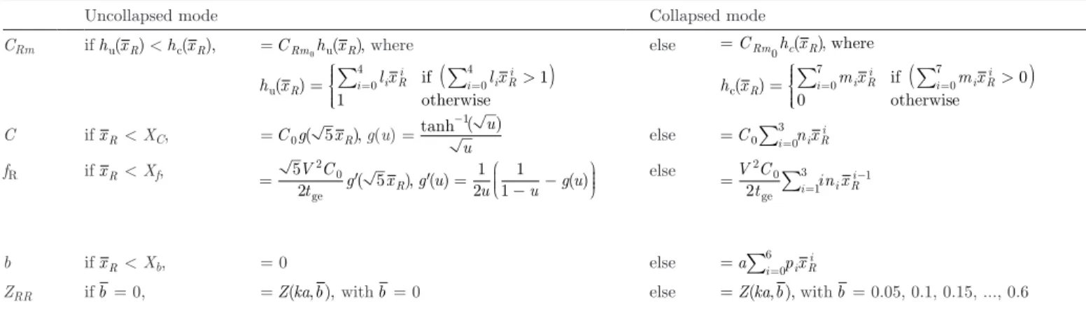
appendix
Table III lists all the uncollapsed- and collapsed-mode expressions for lumped parameters, and the mode transi-tion conditransi-tions. For the uncollapsed mode, we have non-linear equations [21]. For the collapsed mode, we have polynomials for tg/tge = 0.4, 0.5, 0.6, 0.65, 0.73, 0.82, and 0.9, and Pb/Pg = 0, 0.2, 1, and 2.
continuous transition between collapsed and uncol-lapsed regions is ensured by defining the transition points exactly at the intersections of uncollapsed and collapsed mode expressions.
The coefficients of the polynomials and the transition points are provided in supplementary documents ( ). as an example, the tg/tge = 0.73, Pb/Pg = 0.2 case is given in Table IV. simulations at intermediate tg/tge and Pb/Pg values can be performed using interpolation. For tg/tge = 0.58 and Pb/Pg = 0.4, the instantaneous capacitance and compliance should be calculated as
C t t C t t C t t
g/ge=0.58 = 0.2 g/ge=0.5+0.8 g/ge=0.6
CRm P P CRm P P CRm P P
b/ =0.4g = 0.75 b/ =0.2g +0.25 b/ =1g .
Polynomials are sensitive to coefficient precision, and the provided precision should be conserved when they are used in a model.
The normalized compliance is valid for xR/tg < 0.8, and the lumped model is not guaranteed to converge to a solu-tion beyond this value.
The medium impedance is dependent on the frequency, and also on the contact radius in collapsed mode. Its value is introduced through lookup tables. There is a single lookup table for uncollapsed mode, whereas there are 12 lookup tables of collapsed mode for b = 0.05, 0.1, 0.15, 0.2, …, 0.55, 0.6. Impedance at intermediate b values should be interpolated. all of the lookup tables for R1(ka) + jX1(ka) are given as s2p files in the supplementary doc-ument ( ). The frequency parameter corresponds to ka in all files.
references
[1] B. Bayram, G. G. yaralioglu, M. Kupnik, a. s. Ergun, o. oral-kan, a. nikoozadeh, and B. T. Khuri-yakub, “dynamic analysis of capacitive micromachined ultrasonic transducers,” IEEE Trans.
Ultrason. Ferroelectr. Freq. Control, vol. 52, no. 12, pp. 2270–2275,
2005.
[2] a. caronti, a. savoia, G. caliano, and M. Pappalardo, “acoustic coupling in capacitive microfabricated ultrasonic transducers: Mod-eling and experiments,” IEEE Trans. Ultrason. Ferroelectr. Freq.
Control, vol. 52, no. 12, pp. 2220–2234, 2005.
[3] G. G. yaralioglu, a. s. Ergun, and B. T. Khuri-yakub, “Finite-ele-ment analysis of capacitive micromachined ultrasonic transducers,”
ge ge
b if xR < Xb, = 0 else =a∑i=0p xi Ri
6
ZRR if b = 0, = Z ka b( , ), with b = 0 else = Z ka b( , ), with b = 0.05, 0.1, 0.15, ..., 0.6
TaBlE IV. Table of Polynomial coefficients for Pb/Pg = 0.2 and tg/tge = 0.73.
l0 l1 l2 l3 l4 43.324 −54.67 330.07 −876.04 877.55 m0 m1 m2 m3 m4 m5 m6 m7 537.77 −7978.88 50 668.32 −177 920.22 372 639.41 −465 350.30 320 838.34 −94 225.80 XC XF n0 n1 n2 n3 0.2579 0.3045 1.1297 −0.8666 6.0994 −0.1124 Xb p0 p1 p2 p3 p4 p5 p6 0.32 13.0537 −145.5684 625.2401 −1305.847 1349.5205 −552.4294 0
IEEE Trans. Ultrason. Ferroelectr. Freq. Control, vol. 52, no. 12, pp.
2185–2198, 2005.
[4] B. Bayram, M. Kupnik, G. G. yaralioglu, o. oralkan, d. lin, X. Zhuang, a. s. Ergun, a. F. sarioglu, s. H. Wong, and B. T. Khuri-yakub, “characterization of cross-coupling in capacitive microma-chined ultrasonic transducers,” in Proc. IEEE Ultrasonics Symp., 2005, pp. 601–604.
[5] M. Buigas, F. M. Espinosa, G. schmitz, I. ameijeiras, P. Masegosa, and M. dominguez, “Electro-acoustical characterization procedure for cMUTs,” Ultrasonics, vol. 43, no. 5, pp. 383–390, 2005. [6] o. oralkan, B. Bayram, G. G. yaralioglu, a. s. Ergun, M. Kupnik,
d. T. yeh, I. o. Wygant, and B. T. Khuri-yakub, “Experimental characterization of collapse mode cMUT operation,” IEEE Trans.
Ultrason. Ferroelectr. Freq. Control, vol. 53, no. 8, pp. 1513–1523,
2006.
[7] a. caronti, r. carotenuto, and M. Pappalardo, “Electromechanical coupling factor of capacitive micromachined ultrasonic transduc-ers,” J. Acoust. Soc. Am., vol. 113, no. 1, pp. 279–288, 2003. [8] a. nikoozadeh, B. Bayram, G. G. yaralioglu, and B. T.
Khuri-yakub, “analytical calculation of collapse voltage of cMUT mem-brane,” in Proc. IEEE Ultrasonics Symp., 2004, pp. 256–259. [9] I. o. Wygant, M. Kupnik, and B. T. Khuri-yakub, “analytically
calculating membrane displacement and the equivalent circuit mod-el of a circular cMUT cmod-ell,” in Proc. IEEE Ultrasonics Symp., 2008, pp. 2111–2114.
[10] G. G. yaralioglu, a. s. Ergun, B. Bayram, E. Haeggstrom, and B. T. Khuri-yakub, “calculation and measurement of electrome-chanical coupling coefficient of capacitive micromachined ultrasonic transducers,” IEEE Trans. Ultrason. Ferroelectr. Freq. Control, vol. 50, no. 4, pp. 449–456, 2003.
[11] W. P. Mason, Electromechanical Transducers and Wave Filters. new york, ny: Van nostrand, 1942.
[12] G. caliano, a. caronti, M. Baruzzi, a. rubini, a. Iula, r. carot-enuto, and M. Pappalardo, “Pspice modeling of capacitive micro-fabricated ultrasonic transducers,” Ultrasonics, vol. 40, no. 1–8, pp. 449–455, 2002.
[13] a. caronti, G. caliano, a. Iula, and M. Pappalardo, “an accu-rate model for capacitive micromachined ultrasonic transducers,”
IEEE Trans. Ultrason. Ferroelectr. Freq. Control, vol. 49, no. 2, pp.
159–168, 2002.
[14] d. certon, F. Teston, and F. Patat, “a finite difference model for cMUT devices,” IEEE Trans. Ultrason. Ferroelectr. Freq. Control, vol. 52, no. 12, pp. 2199–2210, 2005.
[15] I. ladabaum, X. Jin, H. T. soh, a. atalar, and B. T. Khuri-yakub, “surface micromachined capacitive ultrasonic transducers,” IEEE
Trans. Ultrason. Ferroelectr. Freq. Control, vol. 45, no. 3, pp. 678–
690, 1998.
[16] a. lohfink and P. c. Eccardt, “linear and nonlinear equivalent cir-cuit modeling of cMUTs,” IEEE Trans. Ultrason. Ferroelectr. Freq.
Control, vol. 52, no. 12, pp. 2163–2172, 2005.
[17] H. K. oguz, a. atalar, and H. Koymen, “Equivalent circuit-based analysis of cMUT cell dynamics in arrays,” IEEE Trans. Ultrason.
Ferroelectr. Freq. Control, vol. 60, no. 5, pp. 1016–1024, 2013.
[18] H. K. oguz, s. olcum, M. n. senlik, V. Tas, a. atalar, and H. Koy-men, “nonlinear modeling of an immersed transmitting capacitive micromachined ultrasonic transducer for harmonic balance analy-sis,” IEEE Trans. Ultrason. Ferroelectr. Freq. Control, vol. 57, no. 2, pp. 438–447, 2010.
[19] X. Jin, o. oralkan, F. l. degertekin, and B. T. Khuri-yakub, “characterization of one-dimensional capacitive micromachined ul-trasonic immersion transducer arrays,” IEEE Trans. Ultrason.
Fer-roelectr. Freq. Control, vol. 48, no. 3, pp. 750–760, 2001.
[20] M. n. senlik, s. olcum, H. Koymen, and a. atalar, “radiation im-pedance of an array of circular capacitive micromachined ultrasonic transducers,” IEEE Trans. Ultrason. Ferroelectr. Freq. Control, vol. 57, no. 4, pp. 969–976, 2010.
[21] H. Koymen, a. atalar, E. aydogdu, c. Kocabas, H. K. oguz, s. olcum, a. ozgurluk, and a. Unlugedik, “an improved lumped el-ement nonlinear circuit model for a circular cMUT cell,” IEEE
Trans. Ultrason. Ferroelectr. Freq. Control, vol. 59, no. 8, pp. 1791–
1799, 2012.
[22] B. Bayram, E. Haeggstrom, G. G. yaralioglu, and B. T. Khuri-yakub, “a new regime for operating capacitive micromachined ul-trasonic transducers,” IEEE Trans. Ultrason. Ferroelectr. Freq.
Con-trol, vol. 50, no. 9, pp. 1184–1190, 2003.
[23] s. olcum, y. yamaner, a. Bozkurt, H. Koymen, and a. atalar, “deep collapse operation of capacitive micromachined ultrasonic
transducers,” IEEE Trans. Ultrason. Ferroelectr. Freq. Control, vol. 58, no. 11, pp. 2475–2483, 2011.
[24] s. olcum, y. yamaner, a. Bozkurt, H. Koymen, and a. atalar, “an equivalent circuit model for transmitting capacitive micromachined ultrasonic transducers in collapse mode,” IEEE Trans. Ultrason.
Ferroelectr. Freq. Control, vol. 58, no. 7, pp. 1468–1477, 2011.
[25] s. Timoshenko and s. W. Woinowsky-Krieger, Theory of Plates and
Shells. new york, ny: McGraw-Hill, 1959.
[26] a. ozgurluk, a. atalar, H. Koymen, and s. olcum, “radiation im-pedance of collapsed capacitive micromachined ultrasonic transduc-ers,” IEEE Trans. Ultrason. Ferroelectr. Freq. Control, vol. 59, no. 6, pp. 1301–1308, 2012.
Elif Aydoğdu was born in ankara, Turkey, in
1982. she received her B.s. and M.s. degrees in electrical and electronics engineering in 2004 and 2007, respectively, from Bilkent University, anka-ra, Turkey. she is currently working toward her Ph.d. degree in the same department, where she has been a research assistant since 2004. Her re-search interests included mechanical energy har-vesting and magnetic resonance imaging, and cur-rently she is working on modeling and design of cMUTs.
Alper Özgürlük was born in Kirikkale, Turkey,
in 1990. He received his B.s. degree in electrical engineering in 2012 from Bilkent University, an-kara, Turkey. He is currently working toward his Ph.d. degree in the department of Electrical En-gineering and computer sciences at the Universi-ty of california, Berkeley, ca. His current re-search interests include micromechanical filters, switches, and modeling of cMUTs.
Abdullah Atalar received his B.s. degree from
the Middle East Technical University, ankara, Turkey, in 1974, and his M.s. and Ph.d. degrees from stanford University, stanford, ca, in 1976 and 1978, respectively, all in electrical engineer-ing. He worked at Hewlett-Packard labs, Palo alto, ca, in 1979. From 1980 to 1986, he was on the faculty of the Middle East Technical Univer-sity as an assistant Professor. In 1986, he joined Bilkent University as the chairman of the Electri-cal and Electronics Engineering department and served in the founding of the department where he is currently a Profes-sor. In 1995, he was a Visiting Professor at stanford University. From 1996 to 2010, he was the Provost of Bilkent University. He is presently the rector of the same university. His current research interests include micromachined devices and microwave electronics.
Prof. atalar was awarded the science award of TUBITaK in 1994. He is a Fellow of IEEE and a member of Turkish academy of sciences.
Hayrettin Köymen received the B.sc. and M.
sc. degrees from the Middle East Technical Uni-versity (METU), ankara, Turkey, in 1973 and 1976, respectively, and the Ph.d. degree from Bir-mingham University, UK, in 1979, all in electrical engineering. He worked as a faculty member in the Marine sciences department (Mersin) and Elec-trical Engineering department (ankara) of METU, from 1979 to 1990. since 1990, he has worked at Bilkent University, where he is a profes-sor. His research activities have included underwa-ter acoustic and ultrasonic transducer design, acoustic microscopy, ultra-sonic ndT, biomedical instrumentation, mobile communications, and spectrum management.