PROCEEDINGS OF SPIE
SPIEDigitalLibrary.org/conference-proceedings-of-spieMultiresolution block coding method
for visualization of compressed
images in multimedia applications
A multiresolution block coding method for visualization of compressed images in
multimedia applications
Omer N. Gerek, A. Enis cetin
Bilkent Uriivevsity,
Dept. of Electrical and Electronics Engineering,
Bilkent, Ankara TR-06533, Turkey
E-mail: gerekee. bilkent. edu. tr or cetincee. bilkent. edu. tr
Phone: (90) 312-266 43O7 Fax.' (90) 312-266 j126
ABSTRACT
Multimedia and Picture Archiving and Communication System (PACS) applications require
ef-ficient ways of handling images for communication and visualization14. In many Visual Information and Management Systems (VIMS)
it
may be required to get quick responses to queries. Usually, a VIMS database has a huge number of images and may provide lots of images for each query. For example, in a PACS, the VIMS provides 10 to 100 images for a typical query. Only a few of these images may actually be needed. In order to find the useful ones, the user has to preview each image by fully decompressing it. This is neither computationally efficient, nor user friendly. In this paper, we propose a scheme which provides a magnifying glass type previewing feature. With this method, a multiresolution previewing without decompressing the whole image is possible.Our scheme is based on block transform coding which is the most widely used technique in
image and video coding Inthe first step of our scheme, all of the queried images are displayed in
the lowest possible resolution (constructed from the DC coefficients of the coded blocks). If the user requests more information for a region of a particular image by specifying its size and place, then that region is hierarchically decompressed and displayed. In this way, large amounts of computations and bandwidth usage are avoided and a good user interface is accomplished. This method changes
the ordering strategy of transform coefficients, thus reduces the compression ratio, however this effect is small.
Keywords : Multiresolution imaging, block coding, image communication, D CT.
1. IMAGE ENCODING
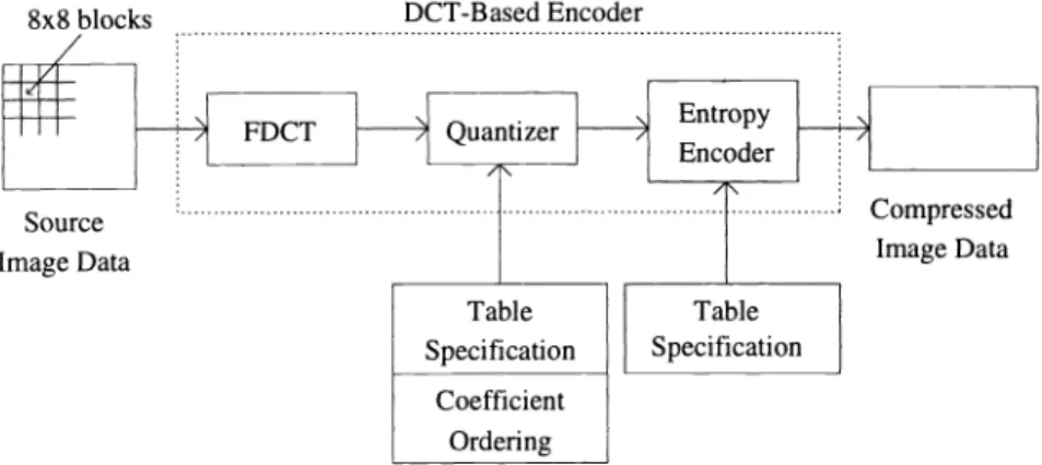
The encoding strategy is based on the block transformation technique. In this aspect, the pro-posed encoder is similar to the well known baseline sequential JPEG coder. In JPEG coding scheme.
each image block whose size ranges from 8x8 to 16x16 is transformed by Discrete Cosine Transform
(DCT)8. The transform domain coefficients are quantized and zig-zag encoding is performed (figure
1).
If the ordering of the transform coefficients are done exactly in a zig-zag manner, The resulting bit-stream does not have a property which can provide a low complexity multiresolution previewing.
Although the low resolution part of the compressed image can be extracted from the compressed data, variable length entropy coding makes this kind of data selection very difficult. In our scheme.
we modify the zig-zag scanning strategy, but at the same time keep the ordering the transform
coefficients in a reasonably descending power manner. If the entropy coded transform coefficients
follow the resolution order, the VIMS will easily extract the data corresponding to the specified resolution.
In our scheme, ordering of the transform coefficients follow the priority order of the rectangular
zones, that is, the order of the sequence is almost zig-zag within each sub-block of size lxi, 2x2,
4x4, .. . , etc. as shown in Figure 2. With this change in the order, optimum Huffman codes of the
resultant data sequences can be determined.
-.
:
-;
>/
:
-/
/
/
->z
Figure 2: Order of the transform coefficients
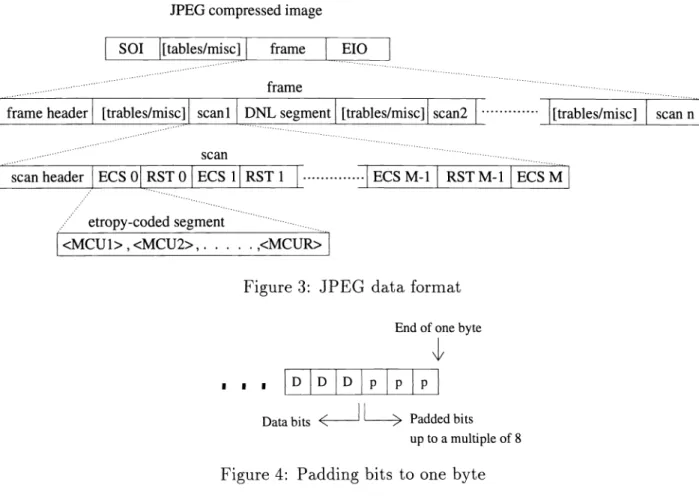
The implementation of a JPEG encoder usually results with some redundancy in the entropy
coded segment shown in figure 3.
If the total number of concatenated bits do not sum up to a multiple of 8 (one byte) at the
end of each entropy coded segment, then some redundant bits are padded to the end. In a regular computer, the smallest storing element is a byte, so every markers between the data, as well as the data itself should contain bits at the multiples of eight.
SPIEVol. 2308 1 955 8x8 blocks Source Image Data Compressed Image Data
Figure 1 : Baseline sequential JPEG encoder
JPEG compressed image sol [tables/misc] frame ElO
frame
Fframeheader [trab1es/misc] scani DNLsegment [trables/misci scan2 [trables/misc] scan n
scan
scan header jECSORST 0 ECS 1 jRST1 . ECSM- 1 RST M- 1 ECS M
..../ etropy-codedsegment
<MCU1> ,<MCU2> • <MCUR>
Figure 3: JPEG data format End of one byte
1 I 1
Databits < > Padded bits up to a multiple of 8
Figure 4: Padding bits to one byte
When the whole of the zig-zag scanned image data is concerned, this kind of redundancy has
possibility to get introduced only once in an 8x8 block. Unfortunately, the redundancy situation is increased to 4 in an 8x8 block. If the only change was in the ordering sequence, this problem would not occur, however our aim is to introduce a suitable strategy for multiresolution image
communication. For this purpose, the encoder part must separate the lxi, 2x2, 4x4 and 8x8 parts of the transform coefficients so that the VIMS can easily provide the block data to the decoder. In order to separate those blocks, each of them should contain data in multiples of bytes. This is the reason to introduce bit padding for each sub-block. Fortunately, the experimental results show that this situation together with the non-optimality of the scanning order of transform coefficients still causes very small decrease in the compression ratio.
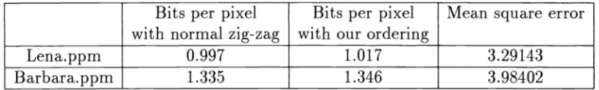
The experimental results for the well known "Lena" and "Barbara" images, each with eight bits per pixel originally, are presented in table 1 . When the multiresolution previewing property achievement is considered, the change in the compression ratio can be acceptable.
One other candidate for organizing the entropy coded segment of the JPEG file format could be
separating the block informations corresponding to different resolutions. In this way, the first part of the file consists of DC coefficients only, the next part consists of the extra three coefficients and the next goes on similarly. This kind of a separation simplifies the operation of the VIMS even further, however, the resultant compressed file size increases to 1•5 to 2 times of the original JPEG file. The main reason for this increase is the marker overhead introduced by the JPEG format for each block
I
L
with normal zig-zagBits per pixelBits
with oper pixel
Mean square error ur ordering
Lena.ppm 0.997 1.017 3.29143
Barbara.ppm 1.335 1.346 3.98402
Table 1: JPEG coding results for regular zig-zag ordering and the proposed ordering methods
Daubechies
Bits per pixel with normal zig-zag
Bits per pixel with our ordering
Mean square error
Lena.ppm 1.063 1.089 4.022
Barbara.ppm 1.451 1.467
Butterworth
4.908
Bits per pixel
with normal zig-zag with our orderingBits per pixel Mean square
error
Lena.ppm 1.051 1.072 4.022
Barbara.ppm 1.439 1.459 4.908
Table 2: JPEG coding results for regular zig-zag ordering and the proposed ordering methods scan. This compression decrease is not acceptable as a trade-off for the operation simplicity obtained for the VIMS.
The next point to experiment is to change the DCT block of the encoder with the Block Wavelet
Transforms (BWT) 6 andtest their performances with the new ordering scheme.
The BWT's are block transforms obtained from perfect reconstruction filter banks. The first
BWT matrix we used was constructed from the Butterworth hR filter bank with L = 1, and the
next matrix was obtained from 8 point Daubechies FIR filter. The two dimensional BWT matrices are separable and orthogonal. Especially the computational complexity for the BWT obtained from the Butterworth filter is very low because three fourths of the matrix entries consist of ones and the rest consist of two different numbers resulting with a great computational saving.
During testing the performances of the BWT's, the Huffman tables for the new quantized
transform coefficients are re-optimized by using our test images. The quantization table itself is also tried to be optimized, however, the original quantization block configuration came out to be good
for the tested BWT's and test images. As a result, the changed parts of the encoder for the BWT
case were the transformation itself and the Huffman code tables. The results for the two previously defined BWT's are presented in table 2. It can be observed that, both the compression ratio and the
mean square error ( defined
as XsizeYsize /sze
szZe(p0jg(jj) Pdecoded(,j))2 ) areinferior to the results obtained with the DCT coding. On the other hand, there is slightly less aliasing in the scaled images for the BWT coding case.2. IMAGE DECODING
At the first stage of the PACS interface, the VIMS provides a query, typically consisting of 10 to 100 lowest resolution images. When the user wishes to visualize a region of one of those images with a higher resolution, only the necessary portion of the coded bit-stream of that region are chosen by the VIMS. Since the blocks of the transform coefficients corresponding to different resolutions are well separated, it is easy for the VIMS to extract the necessary extra information bytes. In our
scheme, there are four resolution levels. According to the required level, the visualization tool decodes
the provided information correspondingly. As an example, the third resolution level is provided by selecting the 4x4 upper left blocks of the 8x8 DCT coefficients. The visualization program computes the 4x4 inverse DCTs of those elements in the blocks and constructs the desired portion of the image like magnifying glass tool with variable magnification. For this case, the resultant pixel values are
. . 3 3 7 7 2 2 (2x
+ 1)ur
(2y+ 1)vr
(2i + 1)uc (2j + 1)virg(z,3) =
c(u)
c(v) f(x,y)cos cos —cosu=0v0x0y0
"
IU 0(1)
where
c(k)=I
fork=0
(21 fork=1,2,3,•
In this equation, the quantization and inverse quantization of the transform coefficients are not
shown. With the quantization effect, the g(i,j) values which are the resultant image pixels at the
lower resolution corresponding to 4x4 block size have quantization distortion. Notice that this is neither the highest nor the lowest resolution available in this system.
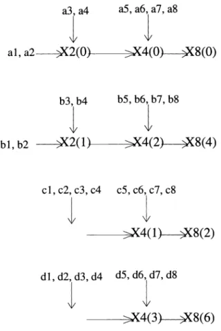
The computational cost at lower resolutions is not high as compared to the highest possible resolution which corresponds to 8x8 block size. Furthermore, if the data corresponding to the next resolution level of the same portion is required, the necessary computations is decreased because the decoding of the previous resolution image supplies some of the multiplications which are also necessary for the present resolution image decoding. In figure 5, the computational saving achieved for the one dimensional case is illustrated.
We can notice that half of the multiplications required in one summation is ready in hand for half of the elements. Even for the fast implementations, keeping the previous multiplication values
reduces the amount of necessary multiplications. This shows that the operations done at a low
resolution directly help for the operations at a higher resolution.
a3, a4 a5,a6, a7, a8 al, a2 X2(O)—X4(O) 9(8(0) b3,b4 b5,b6,b7,b8 bl,b2 9(2(1) X4(2) 9(8(4) ci, c2, c3, c4 c5,c6,c7, c8 X4(1) 9(8(2)
\/
x(n)cos(2ir+1)O x(n)cos(2l)148 LiO x(n)cos(2ir+1)O
=o x(n)cos
(2+1)1=o x(n)cos
(2+1)28 4n=O x(n)cos(2+1)3=o
x(n)cos(2+1)o16\/ =o x(n)cos
(2ir+1)1 16\nO
x(n)cos (2ir+1)216 x(n)cos(2ir+1)316=
al+a2
=
bl+b2
=
X2(O)*cons+a3+a4
=
cl+c2+c3+c4
=
X2(1)*corts+b3+b4
dl+d2+d3+d4
= X4(O)*cons+a5+a6+a7+a8
= X4(1)*cons+c5+c6+c7+c8
= X4(2) *
cons+ b5 + b6 + b7 + b8= X4(3)*cons+d5+d6+d7+d8
di,d2,d3,d4 d5,d6,d7,d8 >X4(3) 9(8(6)Figure 5: Computational saving for incremental inverse DCT
In this figure, X2(O) = X2(1)
=
X4(O)=
X4(1) =
X4(2) =
X4(3)=
X8(O) =X8(2) =
X8(4) =
X8(6) =
(3) SPIEVol. 2308 / 9593. EXPERIMENTAL RESULTS
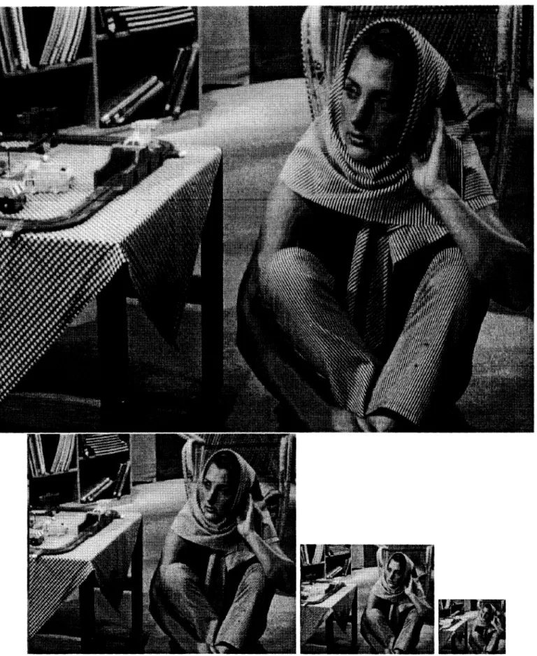
Various types of images are tested for the performance of our coding-decoding scheme. In this paper, the image results for the well known "Barbara" image are presented in figure 7.Inthis figure , thetest image is shown decoded at four different resolutions.
By taking 4x4 inverse DCT of the first 4x4 block of 8x8 transform domain coefficients, a
reasonable downsampling operation is performed together with the necessary low pass filtering. This situation is mainly due to the nice frequency domain properties of DCT. The first 4x4 block of the
8x8 DCTcoefficients have the information corresponding to half the maximum frequency of the 8x8 coefficients itself. As a result, the output in equation 1 has a good downsampling property. This kind of downsampling is better than directly zonal filtering the 8x8 coefficients by retaining the
first 4x4 elements, padding the rest of elements by zeros and taking the 8x8 inverse transform.
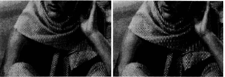
In figure 6, parts of the scaled versions of "Barbara" test image are presented. At the left,
4x4 inverse DCT of the first 4x4 block of 8x8 transform coefficients is used, at the right, the zonal filtering and decimation by a factor 2 is used. The image at the left has significantly less aliasing
effects.
4. CONCLUSIONS
Our experiments show that this kind of a block coding scheme can be used to enable multires-olution viewing in a visualization media. The complexity required for the VIMS is reduced without much trade-off about the compression ratio. The way of downsampling is found to be efficient both in terms of aliasing and visual perception. This achievement is accomplished without changing the basics of the well known JPEG format. Furthermore, there exists some computational savings when
higher resolutions corresponding to the same image data are required for decoding. As a result,
introducing this kind of a utility in a VIMS that already uses JPEG coding is a simple extension to the in hand visualization softwares.
960/ SPIEVol.2308
Figure 7: Test images decoded at 4 different resolutions
5. REFERENCES
[1] H. K. Huang, 0. Ratib, A. R. Bakker, and G. Witte (Ed.), Picture archiving and communication
systems (PACS) in medicine, Springer-Verlag, Berlin Heidelberg, 1991.
[2] J. J. D'Lugin, R. L. Hill, R. G. Jost, A. P. Renter, and J. B. Zimmerman, "Design considerations for a picture archive and communication system (PACS) display station," IEEE Engineering in Medicine and Biology Society 10th Annual International Conference, pp. 489-90, 1988. [3] S. Bhagat, "Multimedia basics for today and tomorrow," The NCR Journal, vol. 4, no. 2, pp.
38-45, December 1990.
[4] T. Arndt, "A survey of recent research in image database management," 1990 IEEE Workshop on Visual Languages, pp. 92-97, University of Pittsburgh, Knowledge Systems Institute, IEEE Computer Society Press, October 1990.
[5] JPEG mt. group, Working draft for development of JPEG, 1991
[6] A. E. çetin, 0. N. Gerek, .
Uluku, " ImageCoding using Block Wavelet Transform" , IEEE Transactions on Circuits and Systems for Video Technology, October 1993.[7] Information Technology - Generic coding of moving pictures and associated audio, Third working draft, New York, July 1993.
[8] N. Ahmed, T. Natarajan, K. R. Rao, "Discrete Cosine Transform", IEEE Trans. on Computers, vol. 23, pp. 90-93, 1974.
[9] Anil K. Jam , Fundamentals of Digital Image Processing, Prentice -Hall, 1989