Journal of istanbul Kültür University 2006/4 pp.l09-120
THE EFFECT OF NOISE AND PARAMETER MISMATCH ON THE
SYNCHRONIZATION OF THE DRlVE-RESPONSE
CHAOTIC SYSTEM
Ioannis P. ANTONIADESl, Amalia N. MILIOVi, Stavros G. STAVRINIDES2, Antonios N. ANAGNOSTOPOVLOS2
Abstract
We present a thorough investigation of the effect ofnoise (internal or extemal) on the synchronization of a drive-response configuration system (unidirectional coupling between two identIcal systems). Moreover, since in every practical implementation of a communication system, the transmitter and receiver circuits (although identical) operate under slightly different conditions it is essential to consider the case of the mismatch between the parameters of the transmitter and the receiver. InOUT work we consider the non-autonomous 2nd order non-linear oscillator system presented by G. Mycolaitis,et aZin Pmc. onth Int. Workshop on Non-linear Dynamics ofElectronic Systems, which is particularly suitable for digital communications.
Index Terms Chaos, nonlinear circuits, synchronization, communication system security.
INTRODUCTION
Computer networks are inherently insecure for communication. Data transmission is not safe unless it is assured that the packets will never pass through a router or a computer, over which there is no control. Traditionally, software techniques were used for data encoding. However, the ever-increasing computer power threatens communication security.
The simplicity of chaos generators, the rich structure of chaotic signals and the fact that chaotic signals can be synchronized caused a. significant interest in possible utilization of chaos for secure communications [1]-[3].
The use of synchronized chaotic systems for communications usually relies on the robustness of the synchronization within the transmitter and receiver pair [2], [4]-[10]. However, if the communication channel is imperfect and lor there is internal noise at the electronic circuitry the distorted signal at the receiver input might cause considerable synchronization mismatch between the transmitter-receiver pair [11]-[15].
in this paper, we consider the dynamical system first presented in [3] and we investigate the synchronization of the system under noisy channel conditions as well as the case where different noise levels are added in the transmitter and the receiver (internal noise) due to electronics. Moreover, since in every practical implementation of a communication system, the transmitter and receiver electronic elements may be slightly different or operate under slightly different conditions, it is essential to consider the case of the mismatch between the parameters of the transmitter and receiver. The paper is organized as follows: The circuit's description and the synchronization properties are presented in section II. The simulation
Ioannis P. Antoniades, Amaiia N. Miliou, Stavros G. Stavrinides, Antonios N. Anagnostopoulos
results obtained are shown in section III. Finally, concluding remarks and discussion are given in section IV.
CIRCUIT DESCRlPTION AND SYNCHRONIZATION PROPERTIES
The transmitter and the receiver are identical circuits similar to those in [3]. The circuits include an integrator based 2nd order
Re
resonance loop, a comparatürH
(the circuit'snon-linear element), an exclusive OR gate, with an input
M
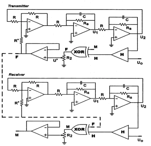
for the extemal source of square pulses M(t) of period T=21f/w,and a buffer to avoid overloading of the XOR gate. The transmitter-receiver system is shown in Fig. 1. The principle of operation is demonstrated below. Here the chaotic pulses U* (t) oc F(Ypt) drive both the resonance loop of the transmitter and the resonance loop of the receiver.Transmitter Uo Uo
c
R H Mc
c
=
r-
F
i
i
iR·i
eceiveri
i
i
i
i
i
~-~-~~:
M+
- -=M XORR2 . H-Fig.
1.
Schematic diagram of the transmitter-receiver system.The Effeel of Noise and Parameter Mismatch on the Synchronization of the Driye-Response Chaotic System Xz = aF(Ypt) -bxz
+
Yz yz = -Xz-byz
Xi = aF(Ypt) - bXi+
Yi Yi = -Xi -bYi F(yi ,t) =H(Yi) EBM(t) (1)The subscripts
'1'
and '2' at the state variables specify the transmitter and the receiver, respectively.Note the same driving term F(Ypt) in the equations for the transmitter and the receiver. The following substitutions have been used in the previous system of equations since the parameters are usually written in a dimensionless form:
Ui Uz t
x
=
U '
o y=
U '
o t=
Re
U'·R
R
U=--
b=-(2)
U ·R"o Rs
The shifred Heaviside function H(y)=H(-y-1) has the following value s H(-y>1)=1and
H(-r51)=O, while the symbol EBdenotes the exc1usive-OR operation and M(t) denotes the normalIzed square pulses of period br/w representing the circuit's driving signa1.
For zero extemal drive M to the XOR-gate the circuit exhibits damped oscillations. For all reasonable
(x/
+
y/
< 1) initial conditions, the corresponding amplitudesofthe variablesx and y converge exponentially (cc e-b) to a stable steady state. However, due to the comparator
H,
for a non-zero driveM
the circuit becomes a periodical1y forced 2nd ordernon-autonomous non-lInear oscillator, exhibiting chaos [1], [2].
Introducing in (1) the error variables Lli
=
x --z Xl and, Lly=
yz - Yi we obtain the equations goveming the error dynamics:Lli
=
bLli+ Lly, Lly=
-Lli -bLly (3)The solution of (3) shows the exponential decrease of the errors for all possible initial errors Llio and LlYo :
Ioannis P. Antoniades, Amaha N. Miliou, Stavros G. Stavrinides, Antonios N. Anagnostopoulos
ili =aexp(-bt) cos(t +rp), ~y = aexp(-bt) sin(t +rp)(4)
where a
=
~iili o2+
~y2o and rp=
aretane ~y o/ ili o)Thus, the synchronization is globally asymptotically stable. This requirement leads to the conclusion that for ili ~ O and ~y ~ O, the corresponding state variables, are robustly synchronized (x2 ~ xi and y2 ~ y ).
i
Consequently, the non-linear functions behave in a synchronous way H (y ) ~ H(y) as well. This result suggests an extremely simple2
i
technique of recovering the signal M(t) at the receiver end. The received signal
F(y ,t)
i
ocU·
(t) is appIied to the XOR unit of the receiver. Due to the sum mod2 property,the signal M(t) can be recovered from the chaotic one F(y ,t)
i
without any errors, according to:F(y ,t)ffiH(y
i
2)=H(yi
)ffiM(t)ffiH(y)~ 2~ H(y )ffi M(t) ffi H(y ) =M(t)
) 1
SIMULATION RESULTS
(5)
Equations ci) have been numerically integrated. Chaotic oscillations are observed for
w=1.1 and a=2.65. The damping parameter b should not be toolarge and in the simulation we use d b=0.02.
Fig. 2 represents the waveforms for ylt} and Y2(t) as well as the difference of the two variables leading to perfect synchronization at about t=250 (RC)-I. There is no noise added to the system either internally (due to electronics) or externally (at the channel).
The signal Md(t) is recovered from the received F(yj,t) by means of the synchronized
H(Y2), (5). in the case examined, the signal M(t) is a train of square periodic pulses (carrying no information), however, M(t) could be a modulated digital signa1. Again, the simulation is without adding external or internal noise to the system.
The Effed of Noise and Parameter Mismatch on the Synchronization of the Drive-Response Chaotic System 2 O ,,::- -4
-6
-22
O ~-2 -4 -6 . 600700
t
(RCf1
800
900 O100
200t
(RCf1
300 400 Fig.2. Characteristic waveforms Yi(t), Y2(t) and (Y2(t)-Yi(t)).Fig. 3 and 4 depict the synchronization with the application of external and internal noise respectively. The external noise is applied on the communication channel and in our simulation is represented by white noise added on F(y],t), where frequencies greater than RC were cutoff. The internal noise is due to the electronics circuitry and is again appIied both on the transmitter and the receiver (added onx], Yi and Xi, Yi variables). Once again frequencies
higher than RC are cutoff.
Different noise amplitudes A, have been utilized ranging from 0.01 % to 50% of the mean signa1 ampIitude. As the noise amplitude A is increased, the synchronization of the system continuously deteriorates and is practically destroyed in both cases (externa1 and internal noise) above a certain noise level.
loannis P. Antoniades, Amalia N. Miliau, Stavros G. Stavrinides, Antonios N. Anagnostopoulos 2 1 ~;:,. -2 -1O 0.4 ~'- ,.., 0.0 -0.4 0'4~ '::f: 0.0 >:-0.4 0'4~ =i' 0.0 >:-0.4 0'4~ =i' ~ 0,0 -0.4 O T 200 T 400 tiRCr' T 600 A (extemal)=0,01 A (extemal)=0.001 i • A (extemal)=0.0005 i • A (extemal)=0.0001 i • i 800 1000
Fig.3. Synchronization with the application of external noise (channel).
4 2 =F o ~ -2 -4 ~ 0.4 ~ >: 0.0 -0.4 0.4 ~ ~o.o -0.4 0.4 ~ ~ 0.0 -0.4 ~0'4~' ~ 0.0 -0.4 O T 200 T 400 t(RCY' T 600 A (intemal)=O.01 A (intemal)=O.001 A (intemal)=O.0005 A (intemal)=O.0001 i • i 800 1000
Fig.4. Synchronization with the application ofinternal noise (electronics).
The artificial noise added at the simulation was produced as follows: A pseudorandom number generatür produces an array of random numbers in the interval [O, 1]. The random numbers are equal to the total number of simulation steps. Then the Fourier transform of this
The Effect of Noise and Parameter Mismatch on the Synchronization of the Drive-Response Chaotic System
senes IS obtained by standard procedures and amplitudes for frequencies larger than a
particular cutoff value are zeroed. The inverse F ourier transform is taken in order to produce the noise series to be use d in the subsequent simulation. in our simulation we cutoff frequencies larger than the characteristic frequency of the system Re. By this "noise filtering" procedure we avoid the dependence of the generated noise on the simulation step. Noise was added at every simulation step, to the signal F(yi,t) coming out of the transmitter (external noise) or to each of the dynamic variables XI, Yi and X2, Y2 of the transmitter and receiver in respect (internal noise). in the latter case, four different noise series were used one for each dynamic variable.
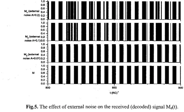
1.0 0.8 0.6 M, (extemal 0.4 nolse A=0.2) 0.2 0.0 1.0 0.8 0.6 0.4 M. (extemal 0.2 nolse A=O.1) 0.0 1.0 0.8 0.6 M. (extemal 0.4 nolse A=O.01) 0.2 0.0 1.0 0.8 M 0.6 0.4 0.2 0.0 800 850 i(Re)"' 900
Fig.5. The effect of external noise on the received (decoded) signal Md(t).
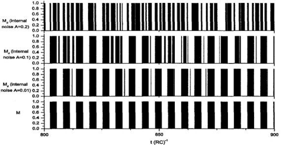
Fig. 5 and 6 represent the sent signal M(t) and the decoded signal Md(t) (received) for external and internal noise respectively and for different noise amplitudes. it is obvious from the comparison of these two figures that the internal noise damages the signal Md(t) in a more severe way than the external noise even in the case of lower noise amplitudes.
Ioannis P. Antoniades, AmaHa N. Miliau, Stavros G. Stavrinides, Antonios N. Anagnostopoulos 1.0 0.8 0.6 Md(Internal 0.4 noiseA~0.2) 0.20.0 1.0 0.8 0.6 Md(Internal 0.4 nolseA~0.1) 0.2 0.0 1.0 0.8 0.6 Md(internal 0.4 nolseA~0.01)0.2 0.0 1.0 0.8 M 0.6 0.4 0.2 0.0 800 850 t(Rer' 900
Fig.6. The effect of internal noise on the received (decoded) signal Md(t).
Moreover, a comparison between the sent and received signals for different amplitudes of extemal noise shows that the application of a decision circuitry before the signal enters the receiver could drastically improve the decoded signal.
Fig. 7 demonstrates the square mean mismatch
J
<
.1y2 >over the initial Lly (=0.3,from F ig.2) and the mean <lifference [ MD ~ ~
!
(M(i) -
M d(i)
)di]
between sigmils M(t) andMit)
in the time interval ofthe simulation, for extemal and internal noise respectively. it is apparent that for noise amplitudes greater that 0.3 the mismatch is growing exponentially.The Effect of Noise and Parameter Mismatch on the Synchronization of the Drive-Response Chaotic System 100000 10000 1000 ;!! 100 >.= ~ 10 v
t
g-0.1 0.01 T iiio-
i-
i -i::==
/- .•-.-/
-/---
=="'.-- ~
---.-.-
..•
=: =
internalexternali
0.1 ci ::!: 0.01 1E-3 ~~_._--/.
---:/.'.~~.---==.=-.~.•.
1---
-.- internalexternali 1E-3 0.01 A (noise amplltude) 0.1Fig.7. The effect ofnoise on the square mean mismatch of the y parameters andMD.
• extemal • Internal
-- Iinear!it of extemal nolse data -- linear !it of Intemal nolse data
1.0 0.9 O.B (') 0.7 ~ '"'>.A 0.6 V
:e-il
..i, 0.5 e. 0.4 0.3 0.2 0.000 0.005 0.010 0.015 A (noise amplitude)•
0.020 0.025•
0.030loannis P. Antoniades, Amalia N. Miliou, Stavros G. Stavrinides, Antonios N. Anagnostopoulos
Fig. 8 ilIustrates the quality of synchronization using a different measure, namely the fractional deviation of the mean square difference of ~
<
i1y2>
from the initialily (=0.3). This quantity is equal to unity for perfect synchronization. The internal noise, is affecting the system's synchronization more than external noise of the same amplitude level.0.5 0.4 0.1 0.0 0.03 0.02 0.01
1---b=002
-0- b=O:0199i
1---b=002
-O-b=O:0199
i
0.05 0.10 0.15 0.20 0.25 0.30 0.35 0.40Fig.9. Sensitivity of the system to parameters aand b.
FinalIy, Fig. 9 ilIustrates the sensitivity of the system to the parameters
a
and b.These parameters depend on resistors used in both circuits and naturalIy may take different values between transmitter and receiver. For a=2.65 and b=0.02 at the transmitter circuit, using a slightly different value of b (b=O.O199) at the receiver circuit does not have any effect on theMDor the square mean mismatch of they parameters regardless of the difference between
a
parameters of the transmitter and the receiver. The system is also robust in terms of deviations (ila) of the values of the parameter
a
between the transmitter and receiver; a deviation in the order ofila=0.35 causes anMD of only about 3%.The Effect of Noise and Parameter Mismatch on the Synchronization of the Drive-Response Chaotic System
CONCLUSION
We have studied the influenee of the external (channel) and the internal (eleetronies) noise on the synehronization of the transmitter-reeeiver pair presented in [3] by numerieal simulation of the equations goveming the system. The results have shown the robustness of the system although internal noise has more influence than external on the synchronization for the same levels of noise amplitudes. Furthermore, synchronization oCClifS,even if the parameters of the drive and response system are mismatched, meaning that the system is robust regarding the employed parameters.
Concluding our study, we could state that there is no doubt that the robustness to noise is very advantageous for the synchronization of the system and its realization with off the shelf electronies.
in terms of the security of communication, however, the robustness to the mismatch of the system parameters would be destructive since an enemy in possession of the same device eould in.principle "tune in" the transmitted signal by adjustingthe parameters aand bso that he approximately matches the transmitter's values.
in order to improve security, one would· require .either a much higher sensitivity of synchronization to system parameters (which would deerease robustness) or a system with a much higher dimensionality in order to increase the number of degrees of freedom an enemy would have to scan in order to synchronize. Implementing systems that would be both robust and also present higher sensitivity could result from a straight forward extension of the very simple system presented in this work.
ACKNOWLEDGEMENTS
This work was supported by the PYTHAGORAS II project of the Greek Ministry of National Education and Religious Affairs and NATO ICS.EAP.CLG.981947.
REFERENCES
[I] G. Chen. Control and Synchronization of chaotic systems, [Online]. Available: ftp.egr.uh.edu/pub/TeX/
[2] G. Kolumban, M. P. Kennedy, L. O. Chua, "The role of synchronization in digital communications using chaos - part II: chaotic modulation and chaotic synchronization", IEEE Trans. On Circuits and Systems I,
vol. 45, no. II, pp. 1129-1140, November 1998.
Ioannis P. Antoniades, AmaIIa N. MlIiou, Stavros G. Stavrinides, Antonios N. Anagnostopoulos
[4] A. Tamasevicious, A. Cenys, G. Myco]aitis, A. Namajunas, "Synchronizing hyperchaos in infinite-dimensional dynamica] systems",1. of Chaos Solitons and Fractals, vol. 9, no. 8, pp. 1403-1408, August 1998.
[5] A. Pikovsky, M. Rosenblum, 1. Kurths,"Synchronizalion: A universal concep! in nonlinear sciences ", ri
paperback edition, vol.12, The Cambridge nonlinear science series, Cambridge University Press, 2003.
[6] T. L. Carroll, L. M. Pecora, "Synchronizing nonautonomous chaotic circuits",JEEE Trans. On Circuits and
Sys!ems lL, vol. 40, no. 10, pp. 646-650, October ]993.
[7] L. M. Pecora, T. L. Carroll, "Synchronization in chaotic systems",Phys. Rev. Lett., vol. 64, no. 8, pp.821-823, February 1990.
[8] M. Murali, M. Lakshmanan, "Drive-response scenario of chaos synchronization in identical nonlinear systems",Phys. Rev. E,vol. 49, no. 5, pp. 4882-4885, June 1994.
[9] K. M. Cuomo, A. V. Oppenheim, "Circuit implementation of synchronized chaos with applications to communications",Phys. Rev. Lett., vol. 71, no. I, pp. 65-68, July 1993.
[10] G. Kolumban, M. P. Kennedy, L. O. Chua, "The role of synchronization in digita] communications using chaos - part I: fundamentals of digital communications",IEEE Trans. On Circuits and Systems I, vol. 44, no. 10, pp. 927-936, October 1997.
[11] E. Sanchez, M. A. Matias, V. Perez-Munuzuri, "Analysis of synchronization of chaotic systems by noise: an experimental study",Phys. Rev. E,vol. 56, no. 4, pp. 4068-4071, October 1997.
[12] M. N. Lorenzo, V. Perez-Munuzuri, V. Perez-Villar, "Noise Performance of a synchronization scheme through compound chaotic signal", Int. 1. of Bifurcalion and Chaos, vol. 10, no. 12, pp. 2863-2870, December 2000.
[13] M. Wang, Z. Hou, H. Xin, "Internal noise-enhanced phase synchronization of coupled chemical chaotic oscillators",1.Physics A, vol. 38, no. ], pp. 145-152, January 2005.
[14] T. L. Carroll, "Noise-resistant chaotic synchronization",Phys. Rev. E, vol. 64, no. 015201, pp. 1-4, July 2001.
[15] X. Yang, T. X. Wu, D. L. Jaggard, "Synchronization recovery of chaotic wave through an imperfect channel",IEEE Antennas &Wireless Propagalion Lett., vol.1,pp. 154-156, January 2002.