T.C.
SELÇUK ÜNİVERSİTESİ FEN BİLİMLERİ ENSTİTÜSÜ
RECOVERY OF CAPROLACTAM FROM AQUEOUS SOLUTION USING REVERSE OSMOSIS
Isse Hassan Ahmed
M.Sc. THESIS
CHEMICAL ENGINEERING DEPARTMENT
April-2015 KONYA All Rights Reserved
iv ACKNOWLEDGEMENT
I would like to express my sincere gratitude to my supervisor Prof. Dr. Erol Pehlivan for his continuous support, encouragement, guidance and advices throughout this research. Indeed, Dr. Pehlivan’s understanding and patience made possible to complete this research on this very time. I would also like to express my deepest gratitude to Dr. Krzysztof Karakulski, for his excellent guidance, caring, patience, and giving practical exposure and fruitful discussion throughout the project without which I would not have succeeded in carrying out this research. I would like to also thank the academic staff of Chemical Engineering Department at each of Selcuk University and West Pomeranian University, Szczecin for their untiring support and guidance throughout my study. I owe a debt of gratitude to each and every one of them.
I would also like to thank my parents for always being there for me; supporting me and encouraging me with their best prayers and wishes. A very special thanks goes out to my elder brother Abdulkadir Hassan AHMED for his invaluable support, motivation and encouragement. I must also acknowledge my wife and best friend, Deka, without whose love, encouragement and assistance, I would not have finished this thesis. She was always there cheering me up and stood by me through all times.
Finally, I would like to thank my friends and countrymates in Konya, thank you for listening, offering me advice, and supporting me through this entire process. Special thanks to my roommate İlker Karalı for his continueous help and dedication throughout my stay in Turkey.
v ABSTRAT
M.Sc. THESIS
RECOVERY OF CAPROLACTAM FROM AQUEOUS SOLUTIONS
USING REVERSE OSMOSIS (RO) PILOT PLANT
Isse Hassan AHMED
SELCUK UNIVERSITY
GRADUATE SCHOOL OF NATURAL AND APPLIED SCIENCE CHEMICAL ENGINEERING DEPARTMENT
Supervisor
Prof. Dr. Erol PEHLİVAN 2015, 80 pages
In this study, the performance of BW3025 (FilmTec), polyamide-based thin-film composite reverse osmosis membrane (RO), in a spiral-wound element for the recovery of caprolactam from an aqueous solution has been investigated. The experimental tests of the RO membrane were carried out using pure water (permeate from a nanofiltration system), brackish water (2000 ppm NaCl) and caprolactam solution (1000 ppm) and were evaluated based on the permeate flux and rejection of the dissolved solids at different transmembrane pressures. The RO membrane provided a rejection of 99.47% for brackish water and 99.74% for caprolactam and an average permeate flux of 65 dm3/ h. It was also found that the RO membrane element has experienced no fouling during the experiments.
Keywords: Caprolactam, Composite membranes, Recovery, Reverse Osmosis, Wastewater treatment
vi ÖZET
YÜKSEK LİSANS TEZİ
TERS OZMOZ PİLOT TESİSİ KULLANARAK SULU ÇÖZELTİLERDEN KAPROLAKTAM GERİ KAZANMA
Isse Hassan AHMED
SELÇUK ÜNİVERSİTESİ FEN BİLİMLERİ ENSTİTÜSÜ
KİMYA MÜHENDİSLİĞİ ANABİLİM DALI
Danışman
Prof. Dr. Erol PEHLİVAN 2015, 80 sayfa
Bu çalısmada, sulu çözeltiden kaprolaktam geri kazanımı için, spiral sarmallı BW3025 (FilmTec) modül içinde poliamit’den yapılmış ince film kompozit ters ozmoz membranın performansı incelenmiştir. Ters ozmoz membran için deneysel testler, saf su (nanofiltrasyon sisteminden geçen), tuzlu su (2000 ppm NaCl) ve kaprolaktam çözeltisi (1.000 ppm) kullanılarak gerçekleştirilmiş ve farklı transmembran basınçlarında, çözünmüş katıların süzüntü akısı ve rejeksiyonuna bağlı olarak değerlendirilmiştir. Ters ozmoz membranı, tuzlu su için 99.47% ve kaprolaktam için 99.74% rejeksiyon ve 65 L/h ortalama süzüntü akı sağlamıştır. Aynı zamanda, deneyler sırasında ters ozmoz (TO) membranda hiçbir kirlenmenin olmadığı görülmüştür.
Anahtar Kelimeler: Kaprolaktam, Kompozit membranlar, Geri kazanma, Ters osmoz, Atıksu arıtma
vii
CONTENTS
DECLARATION/TEZ BİLDİRİMİ ... iii ACKNOWLEDGEMENT ... iv CONTENTS... vii LIST OF TABLES ... ix LIST OF FIGURES ... x LIST OF ABBREVIATIONS ... xi INTRODUCTION ... 11.1 Background of the Research ... 1
1.2 Problem Statement ... 4
1.3 Objectives ... 5
1.4 Scope of the Thesis ... 5
LITERATURE REVIEW ... 7
2.1 Caprolactam ... 7
2.2 Short History of Membranes ... 9
2.3 Types of Membranes ... 10
2.3.1 Isotropic Membranes... 11
2.3.2 Anisotropic Membranes ... 13
2.4 Types of Membrane Processes ... 14
2.4.1 Microfiltration (MF) ... 15
2.4.2 Ultrafiltration (UF) ... 16
2.4.3 Nanofiltration ... 16
2.5 Reverse Osmosis (RO) ... 17
2.5.1 Definition of Reverse Osmosis ... 18
2.5.2 RO Process Description ... 20
2.6 Mass Transport Mechanism through Membranes ... 22
2.6.1 Solution-Diffusion Model ... 25
2.6.2 Concentration Polarization (CP) ... 26
2.6.3 Model Equations ... 28
2.7 Polymers Used as Membrane Materials ... 31
viii
2.7.2 Thin Film Composite Membranes ... 33
2.8 Membrane Modules ... 35
2.8.1 Plate-and-frame Modules ... 35
2.8.2 Tubular Modules ... 36
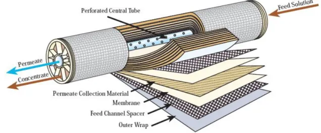
2.8.3 Spiral-wound Modules ... 37
2.9 Membrane Fouling ... 38
2.9.1 Fouling and Concentration Polarization... 39
2.9.2 Factors Contribute to Fouling ... 40
2.9.3 Methods of Fouling Control ... 41
METHODS AND MATERIALS ... 42
3.1 Introduction ... 42
3.2 Instrumentations ... 42
3.3 Chemicals and materials ... 43
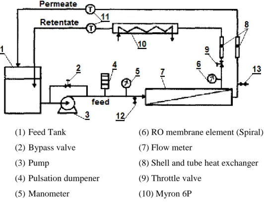
3.4 Experimental Setup and Pilot Plant Description ... 43
3.5 Experimental Procedures ... 47
3.3.1 Preparation of Brackish Water ... 47
3.5.2 Preparation of Caprolactam Solution ... 48
3.5.3 RO Experiments ... 48
RESULTS AND DISCUSSION ... 50
4.1 Pure Water Flux ... 50
4.2 Performance at Manufacturer’s Specified Conditions ... 51
4.3 Caprolactam Rejection Test ... 53
4.4 Caprolactam Concentration Experiment ... 55
4.5 Fouling Test ... 57
4.6 Effect of Operation Conditions on Membrane Performance ... 58
4.6.1 Effect of Transmembrane Pressure ... 58
4.6.2 Effect of Feed Concentration ... 59
4.6.3 Effect of Feed Temperature ... 59
4.6.4 Effect of pH ... 60
CONCLUSIONS ... 61
ix LIST OF TABLES
TABLE NO. LEGEND PAGE
2.1 Physical and chemical properties of caprolactam 8
3.1 Membrane specifications 47
3.2 Membrane operation characteristics 47
x LIST OF FIGURES
FIGURE No LEGEND PAGE
Figure 2.1 Schematic diagrams of isotropic membranes 13
Figure 2.2 Range of nominal membrane pore sizes 14
Figure 2.3 Concept of osmosis and reverse osmosis phenomena 19 Figure 2.4 Reverse Osmosis membrane module and nomenclature 21 Figure 2.5 Motion of permeant molecule in a polymer matrix 24 Figure 2.6 Concentration polarization representation at the wall of
RO membrane 27
Figure 2.7 Chemical structure of a cellulose repeat unit 32 Figure 2.8 Schematic representation of a thin-film composite
membrane 34
Figure 2.9 Plate-and-frame module of reverse osmosis (RO) 36
Figure 2.10 Spiral-wound membrane element 37
Figure 3.1 Schematic diagram of reverse osmosis pilot plant 45
Figure 3.2 Dimensions of BW30-2540 membrane element 46
Figure 3.3 Schematic diagram of caprolactam concentration
experiment 51
Figure 4.1 Flux and rejection of desalination membrane
BW30-2540 with brackish water 53
Figure 4.2 Flux and rejection of caprolactam at different pressures 55 Figure 4.3 Comparison of pure water, brackish water and
caprolactam solution fluxes 56
Figure 4.4 Effect of concentration on flux and rejection of
caprolactam 58
Figure 4.5 Relation of recovery rate and the concentrate solution
concentration factor 59
Figure 4.6 Comparison of pure water fluxes before and after
caprolactam experiment 60
Figure 4.7 Influence of (a) feed pressure, (b) feed concentration, (c) feed temperature, and (d) feed pH on water flux and
xi LIST OF ABBREVIATIONS BW - Brackish Water CA - Acetylated Cellulose Cb - Bulk concentration CF - Feed concentration
COD - Chemical Oxygen Demand
CP - Concentration Polarization
CP - Permeate concentration
CPF - Concentration Polarization Factor
CPL - Caprolactam
Cs - Salt concentration
TFC - Thin-film Composite
Cwall - Solute concentration at the membrane surface
Di - Diffusivity coefficient
EPS - Extracellular Polysaccharides
gfd - gallons per square foot per day
IUPAC - International Union of Pure and Applied Chemistry
Js - Salt flux
Jw - Water flux
Ks - Solute permeability constant
Kw - Water permeability constant
MF - Microfiltration
MW - Molecular Weight
NaCl - Sodium Chloride
NDP - Net Driving Pressure
NF - Nanofiltration
ppm - Parts per million
QF - Feed flow rate
QP - Permeate flow rate
Qs - Salt flow rate
RO - Reverse Osmosis
TDS - Total Dissolved Solids
TOC - Total Organic Carbon
UF - Ultrafiltration
VCR - Volume Concentration Ratio
ΔP - Pressure difference across the membrane
1 CHAPTER 1
INTRODUCTION
1.1 Background of the Research
Nylon forms the second most important manmade textiles after polyester. Because of the enormous population growth and urbanization, the production of nylon 6 fibers has dramatically increased. According to Beijing Hengzhou Bozhi International Information Consulting Co., Ltd. (also known as QYResearch) reports, in 2012, global consumption of nylon filament yarn and fiber increased 3.9% against the marginal growth of 0.8% in 2011. As a precursor to nylon 6, caprolactam (C6H11NO, CPL) is an
important chemical raw material which has wide and considerable usage in the manufacture of Nylon-6 fiber and resins. The world production of caprolactam totalled 4.68 million tons in 2012 and the demand is expected to be ever increasing in the next years. Nylon 6 fibers have an exerting influence in the consumption of caprolactam and made up over 66% of total demand in 2012. Nylon 6 fibers have become the most preferred material in numerous textile and carpets application because of their excellent chemical and physical characteristics such as light weight and high tensile strength. The demand of caprolactam in nylon 6 resin production industry used in engineering plastics and electronic applications is also expected to be ever growing in the next few years.
Nylon 6 is formed from the hydrolytic polymerization of caprolactam. The process reaches a stage of equilibrium when about 90% of the reaction mass is the polymer. This means that the effluent of the process contains un-reacted caprolactam as
2 it’s the main constituent which causes both economic profit reduction and significant pollution to the environment and exerts toxicity to living beings. Exposure to caprolactam at the work place is known to cause dermal, eye and upper respiratory tract irritation but clear dose-response data are lacking (Kelman, 1986; Billmaier et al., 1992). Therefore, it is essential to recover the caprolactam and its low molecular weight oligomers to make the process green, kind to the environment and human being and economically more viable.
A number of processes have been put to use in the elimination and recovery of caprolactam from the wastewater for reuse. Solvent extraction techniques have been used to purify aqueous solutions of caprolactam by extracting colour, oxidizable impurities and oily materials. Solvent used for extraction must be immiscible with water, a good solvent in impurities and oil, a non-solvent for caprolactam and economical and non-toxic. Benzene was used as the extractant in many researches. As well known, benzene is known for its tendency to induce leukemia in human. Toluene is considered as a good alternative for benzene. Many other extractants with less toxicity have been tested in recent years, such as ethers, esters, alcohols and ketones. However, these methods are still not ideal for recovery of caprolactam from wastewater because these solvents are usually toxic, flammable and volatile and the processes are economically unfavorable as they use additional chemicals. In addition, studies have also been made to treat such caprolactam-containing wastewater by biological degradation of caprolactam. Kulkarni (1998) reported the use of microorganisms to consume and break down the caprolactam in the wastewater i.e. bioremediation. Among the microorganisms used is
Pseudomonas aeruginosa MCM B-407, which is a microorganism isolated from
activated sludge (Kulkarni and Kanekar, 1998). Another caprolactam-degrading bacteria, alcaligenes faecalis, used by Baxi (2002), is also an example for bioremediation of wastewater containing caprolactam (Baxi and Shah, 2002).
Membrane technologies have become proven and well-established in recent years as alternatives for environmental applications to conventional mass-exchange technology such as absorption, adsorption or extraction (Noble, 1987). They are physical
3 processes and often consume less energy with better separation efficiency than conventional separation processes and produce no problematic by-products. Membranes can be defined as semi-permeable barriers that restrict certain molecules from passing through the membrane, thereby achieving separation. Membrane separation can occur based on the size exclusion, differences in diffusivity and solubility of the permeant in the membrane or both. There are many noteworthy advantages of using membranes for industrial processes as compared with the conventional processes, as listed below:
Being reliable for consistent production with very high selectivity. No requirement for phase change or chemical additives,
Simplicity in concept and operation,
Modular design and ease of scale up; requirement of small footprint as well as no requirement of large space,
Relatively low energy consumption
High efficiency for raw materials use and potential for recycling of byproducts, Substantially reduced equipment size and
Easy integration into simple automation and remote control system, making its operation simple.
To a large extent, reverse osmosis (RO) and nanofiltration (NF) membrane processes are largely getting employment in wastewater treatment. According to earlier studies, RO and NF exhibit and outstanding performance in removing organic compounds when organic compounds have ionizable functional groups causing electrostatic repulsion or the solute sizes are larger than the membrane pore sizes (Cadotte, 1985). However, these studies have typically considered relatively large compounds (e.g., molecular weight (MW) > 150 g/mol) and/or relatively hydrophobic compounds (e.g., logarithm of octanol–water partition coefficient > 2.0). There are only a few studies in the literature that considered the rejection of small uncharged organic compounds by RO and NF membranes (Thiel and Loyd, 1990). As a result, this study is devoted to the investigation of the caprolactam rejection from nylon plant wastewater
4 using reverse osmosis so that the caprolactam will be reused and the process will be more environmentally friendly and economically viable.
1.2 Problem Statement
Caprolactam is an important bulk chemical in the manufacture of synthetic fibers and resins particularly Nylon 6 as it is the monomer used as starting point of the polymerization process of these resins. Almost all caprolactam is used to produce Nylon 6, which is used in the production of many different households and daily-used materials and products including carpets, furniture, apparel, appliance parts, and brush bristles (Cooper et al., 1993). Due to growth of population and progressive urbanization, there has been an increasing demand for fibers and resins and, in turn, for caprolactam all over the world (Hong and Xu, 2012). In the production of nylon 6 for example, a great deal of wastewater containing about 5–10% of caprolactam is discharged to the environment. As a consequence, reduction in economic profit and an increase in the Chemical Oxygen Demand (COD) of the wastewater take place which, in turn, raise economic and environmental challenges to the industry. It is also reported that exposure to caprolactam cause nasal, respiratory and eye irritation in both animals and humans. As a consequence, it is of interest to evaluate appropriate separation techniques to treat such wastewater prior to discharging to the environment while recovering caprolactam from the wastewater for reuse. In this study, the performance of reverse osmosis (RO) for the removal of small amounts of caprolactam from wastewater was investigated. The effects of operating conditions (e.g., temperature, pressure and feed flow) on the separation performance were studied. In addition, membrane fouling was also investigated to gain a better understanding of how fouling behavior influenced the separation performance.
5
1.3 Objectives
This thesis aims to investigate the performance of membrane processes for the removal of small amounts of caprolactam from wastewater. As all processes involving membranes can be expected to provide excellent recovery of caprolactam, the investigation focuses on the recovery of caprolactam by reverse osmosis (RO). The main objectives are as follows:
To determine the capacity of reverse osmosis to recover caprolactam from nylon wastewater and identify the main governing factors.
To identify the effect of the operating conditions (such as temperature and pressure) on the separation process.
To demonstrate the membrane processes in pilot scale and define the optimum operation strategies for treatment of wastewater containing caprolactam.
1.4 Scope of the Thesis
The scope of this thesis research is: a) Pure Water Flux
The membrane flux stabilization is done before the caprolactam recovery experiment is conducted.
b) Performance at Manufacturer’s Specified Conditions
The performance of the membrane BW3025 was measured using the conditions used by FilmTec Process Solutions in their characterization studies
c) Caprolactam Rejection Test
The rejection of caprolactam from aqueous solution was tested i.e. a preliminary experiment of caprolactam solution to determine the optimum operation
6 conditions (feed concentration, pressure and temperature) that give the best flux and rejection.
d) Caprolactam Concentration/Recovery Experiment
Caprolactam recovery from aqueous solution at the optimum conditions
e) Fouling Test
Fouling of the membrane element was tested by measuring the permeability of the membrane with pure water flux after the caprolactam recovery experiment and comparing with flux before the experiment.
7
CHAPTER 2
LITERATURE REVIEW
2.1 Caprolactam
Caprolactam, (CH2)5C(O)NH, is a white crystalline substance highly soluble in
water and organic solvents, such as alcohol, ether, and benzene, and is hydrolyzed in aqueous acid and alkaline solutions to ε-aminocaproic acid, H2NN-(CH2)5CCOOH. In
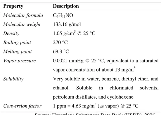
late 1800s, caprolactam was obtained through the cyclization of ε-aminocaproic acid, the product of the hydrolysis of caprolactam, and that was the sudden discovery of this important chemical. After gaining the commercial significance as raw material to Nylon-6, various approaches have been introduced for the production of caprolactam. The state-of-the-art approach of caprolactam synthesis is the conversion of cyclohexanone to its oxime and treating it with an acid which induces the Beckmann rearrangement to give caprolactam. An important property of caprolactam is its ability to polymerize, forming the valuable polymer polycaproamide (nylon 6). Other than the production of nylon 6 and its derivatives, caprolactam gets applications in the manufacture of synthetic leather, paint vehicles, polyamide plastics for packaging foodstuffs and other products, and for the synthesis of the amino acid lysine (Bradley et al., 2004). Having a melting point of 69.3°C, caprolactam is described as a solid at room temperatures. However, it has a significant vapor pressure (Ferguson and Wheeler, 1973). The physical and chemical properties of caprolactam are shown in Table 1.
8 Experiments show that the skin and the mucous membranes in humans are susceptible to the irritant effects of caprolactam. There are only rarely reported cases for potential abnormal sensitization to caprolactam in man and is considered negligible. Because of the missing data on exposure levels, there is no evaluation of reports on disturbance of menstrual cycle and pregnancy of employees in the caprone industry is possible, especially because there is no confirmation of effects on reproduction by animal experiments (Schlottmann et al., 2011)
Table 2.1: Physical and Chemical Properties of Caprolactam
Property Description
Molecular formula C6H11NO Molecular weight 133.16 g/mol
Density 1.05 g/cm3 @ 25 °C
Boiling point 270 °C
Melting point 69.3 °C
Vapor pressure 0.0021 mmHg @ 25 °C, equivalent to a saturated vapor concentration of about 13 mg/m3
Solubility Very soluble in water, benzene, diethyl ether, and ethanol. Soluble in chlorinated solvents, petroleum distillates, and cyclohexene
Conversion factor 1 ppm = 4.63 mg/m3 (as vapor) @ 25 °C
Source: Hazardous Substances Data Bank (HSDB), 2006.
Caprolactam showed neither mutagenic nor clastogenic potential with respect to most of the different genetic endpoints (Fox et al., 1985). Positive results in vitro cytogenetic tests are reported only with high concentrations (> 10 mM). However, several tests in vitro and in vivo show induction of mitotic recombination. The relevance of this effect remains unclear, especially taking into account the negative results in rats and mice carcinogenicity bioassays (Reinhold et al., 1998). Caprolactam fume/dust at 68 mg/m3 is irritating to human skin. In some rare cases allergic contact dermatitis, resp.
9 positive patch-test reactions were reported. Disturbance of the menstrual function and an increased number of toxicities, premature delivery and post-natal hemorrhages were reported in female employees in the processing industry, where exposure to other compounds was also possible (Serota et al., 1988).
2.2 Short History of Membranes
The technical utilization of membrane processes began just 40 years ago when synthetic membranes were developed and used in industrial applications. However, the membrane phenomenon was first noted in the middle of the 18th century and the first recoded study was done by Nollet when he discovered that the bladder of a pig passes ethanol favorably when it is put in contact with water-ethanol mixture on one side and pure water on the other side (Nollet, 1748). It is considered that Nollet was probably the first scientist who identified the relation between a semipermeable membrane and the osmotic pressure. Later on, Graham studied the diffusion of gases through different media by conducting precise methodical studies on mass transport in semipermeable membranes and finally came to know that rubber exhibits different permeabilities to different gases (Graham, 1866).
In most of the studies at that era, naturally existing materials such as animal bladders and gum elastics were first tested for membrane permeation. The first artificially prepared semipermeable membrane was first introduced in 1867 when cupric ferrocyanide was precipitated in a thin layer of porous porcelain (Traube, 1867) and that type of membrane was fundamentally used in the studies of osmosis later on. The osmotic phenomena and mass transport through membranes was thoroughly understood after some studies interpreted diffusion in liquids as a function of concentration gradients. Soon after, the osmotic pressure of dilute solutions was explained thermodynamically. Finally, Dannon described the theory of membrane equilibria and membrane potentials with his publications and that outlined the end of early history of
10 membrane science with most of the basic phenomena satisfactorily described and theoretically interpreted (Donnan, 1911).
A new phase of membrane science and technology started with the beginning of the twentieth century. The first synthetic membranes were developed in 1908 and were basically made of a filter paper impregnated with a solution of nitrocellulose in glacial acetic acid (Bechhold, 1908). The advantage of these early synthetic membranes was the ability to prepare and accurately produce membranes with different permeabilities by varying the ratio of acetic acid to nitrocellulose. Early nitrocellulose membranes got applications in many industries. They were used as ultrafilters for the separation of macromolecules and fine particles from an aqueous solution. In addition, these membranes became an ideal choice for applications in microbiological laboratories like isolation and enumeration purposes. Presently, the membrane industry is a well-established industry which is expanding rapidly. Regardless of the ever increasing strict environmental standards and the plenty of new applications appearing every day, membranes keep the challenge and continue to perform efficiently and effectively.
2.3 Types of Membranes
A membrane is a thin interface with a sheet-like structure that acts as a boundary and selectively controls the permeation of chemical species (ions and organic molecules) in contact with it. A membrane may be molecularly homogeneous, that is, completely uniform in composition and structure, or it may be chemically or physically heterogeneous, for example, containing holes or pores of finite dimensions or consisting of some form of layered structure. A normal filter meets this definition of a membrane. However, it should be distinguished from membranes. Conventionally, the term filter is usually limited to structures that separate particulate suspensions larger than 1 to 10 μm. There are two classes of membranes commonly used namely: isotropic membranes and anisotropic membranes.
11 2.3.1 Isotropic Membranes
The isotropic membranes are unique in their uniformly structured composition. These membranes can have tiny interstices (pores) that make the liquid pass easy while others are dense. In these membranes, the resistance to mass transfer strongly depends on the total membrane thickness i.e. the permeation rate increases when the thickness of the membrane is decreased. Isotropic membranes are classified as follows according to the kind of pores in it.
Microporous Membranes
Microporous membranes closely resembles in terms of structure and function to the traditional filters. They have stiff structure with interconnected and randomly distributed pores. The only difference between the pores of these membranes and the ones in the conventional filters is that they are extremely small, approximately 0.01 to 10 μm in diameter. Thus, they completely reject all particles larger than the largest pores. Particles with a diameter less than 10 μm and greater than 0.01 μm are partially rejected according to the pore size distribution of the membrane. Particles much smaller than the smallest pores will freely pass through the membrane. It can be concluded from these observations that molecular size and pore size distribution play a key role in the separation of solutes by microporous membranes.
Nonporous, Dense Membranes
As can be understood from their name, nonporous, dense membranes do not have intersects or pores. Instead, they are made of a film with relatively highly density through which permeants are transported by diffusion under the driving force of a pressure, concentration, or electrical potential gradient. In nonporous membranes, the relative transport rate demonstrated as diffusivity and solubility in the membrane
12 material defines the separation of various components of a mixture. Thus, nonporous, dense membranes may have different separation degrees for two permeants with the same or similar molecule sizes if the driving force, concentration in the membrane material, is significantly different. Generally, reverse osmosis processes use dense membranes to perform their separations.
Electrically Charged Membranes
Electrically charged membranes are either dense or microporous membranes, but are usually microporous with very fine pores carrying fixed positively or negatively charged ions on their walls. When the membrane has fixed positively charged ions, it ties up with the anions in the surrounding fluid and is called an anion-exchange membrane. On the same way, a membrane containing fixed negatively charged ions is called a cation-exchange membrane. The separation mechanism of charged membranes is exclusion of ions of the same charge as the fixed ions of the membrane structure. A very limited permeation by pore size also happens in charged membranes. Therefore, the charge and concentration of the ions in solution have a great deal of effects on the separation degree. For instance, solutions with high ionic strength have a very low selectivity and the divalent ions have exclusion efficiency which is much higher than that of monovalent ions. Electrically charged membranes commonly get applications in electrodialysis where electrolyte solutions are processed.
13 Figure 2.1 Schematic diagrams of Isotropic Membranes
2.3.2 Anisotropic Membranes
The inverse relation between a membrane thickness and the transport rate of a species through the membrane is already proved. Another fact is that high transport rates are preferable in membrane separation processes for economic reasons. Therefore, the thinner the membrane, the higher the transport rate and the better the membrane performance. The limit of the mechanically strong, long-lasting and not easily defecting films is about 20 μm thickness according to the conventional film fabrication technology. New membrane fabrication techniques were developed in the last 30 years which produce anisotropic membrane structures and the development of these techniques is considered a major breakthrough in membrane technology. Anisotropic membranes consist of three layers; top layer which is an extremely thin surface layer and this layer is the separating layer, porous ultrafiltration substructure which makes a support to the top thin layer and a non-woven backing at the bottom. The top layer and the other two layers may be manufactured in a single operation or separately. In composite membranes, the layers are usually made from different polymers. The separation properties and permeation rates of the membrane are determined exclusively by the surface layer; the substructure functions as a mechanical support. The advantages of the higher fluxes provided by anisotropic membranes are so great that almost all commercial processes use such membranes.
14
2.4 Types of Membrane Processes
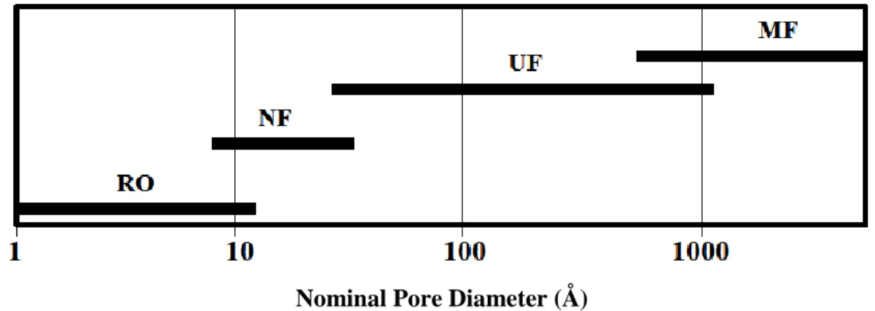
Water and wastewater treatment processes employ different types of membrane processes. The four developed industrial membrane separation processes are microfiltration (MF), ultrafiltration (UF), nanofiltration (NF) and reverse osmosis (RO). These processes are long-standing and prevailing and there are quite a number of companies with deep-rooted experience in the industry. Fig. 2.2 shows the range of nominal membrane pore sizes for each process. The first three processes are governed by the same mechanism of molecular sieving through increasingly fine pores. Microfiltration membranes are only capable of filtering the colloidal particles and bacteria from 0.1 to 10 μm in diameter. Ultrafiltration membranes do best in filtering the macromolecules, such as proteins, from solutions. Nanofiltration membranes are in-between the ultrafiltration membranes and reverse osmosis membranes. These membranes exhibit high rejections for the di- and trisaccharides sucrose and raffinose with molecular diameters of 10–13 Å, but freely pass the monosaccharide fructose with a molecular diameter of about 5 – 6 Å.
Figure 2.2 Range of nominal membrane pore sizes Nominal Pore Diameter (Å)
15 Compared to other membrane processes, the mass transport mechanism of reverse osmosis is quite different. As mentioned earlier, reverse osmosis membrane has extremely small pores (3-5 Å in diameter) such that they are within the range of thermal motion of the polymer chains that form the membrane. The accepted mechanism of transport through these membranes is called the “solution-diffusion model”. According to this model, solutes permeate the membrane by dissolving in the membrane material and diffusing down a concentration gradient. Separation occurs because of the difference in solubilities and mobilities of different solutes in the membrane. The principal application of reverse osmosis is desalination of brackish groundwater or seawater. Following is a brief description of microfiltration, ultrafiltration, nanofiltration and reverse osmosis with the last being detailed.
2.4.1 Microfiltration (MF)
Microfiltration (MF) is defined as a process that uses microporous medium like a membrane filter to remove particles and biological objects that range from 0.1 μm to 10.0μm. MF is the process with the largest pore size among the membrane filtration systems. Based on the pore size sequence, MF falls between ultrafiltration and conventional granular media filtration. In terms of characteristic particle size, MF can retain particles in the size of the lower part of the conventional clays and the upper part of humic acid. This range is smaller than that of the bacteria, cysts and algae and larger than the range of viruses. MF is principally used for the reduction of turbidity and the removal of suspended solids. Microfiltration membranes are commonly used for sensitive applications where penetration of even only one particle or bacterium through the membrane can be critical. Therefore, it is extremely important to keep the membrane free from wears and tears and free from membrane defects or oversized pores. There are several tests used in the characterization of the membrane pore size and their distribution.
16 2.4.2 Ultrafiltration (UF)
Ultrafiltration (UF) is a process used to separate extremely small particles and dissolved molecules from fluids. This process uses a very fine porous membrane to separate water and solutes in the micro range from macromolecules and colloids. The average pore diameter of the membrane is in the 10–1000 ˚A range. The finely porous surface layer or skin is supported by a much more open microporous substrate. The finely porous surface layer performs the separation; the microporous substrate provides mechanical strength. The membranes discriminate between dissolved macromolecules of different sizes and are usually characterized by their molecular weight cut-off, a loosely defined term generally taken to mean the molecular weight of the globular protein molecule that is 90% rejected by the membrane. Ultrafiltration and microfiltration are related processes—the distinction between the two lies in the pore size of the membrane. Microfiltration membranes have larger pores and are used to separate particles in the 0.1–10 μm range, whereas ultrafiltration is generally considered to be limited to membranes with pore diameters from 10 to 1000 ˚A.
2.4.3 Nanofiltration
Nanofiltration membranes, which fall into a transition region between pure reverse osmosis membranes and pure ultrafiltration membranes, are also called loose reverse osmosis, low-pressure reverse osmosis. Typically, nanofiltration membranes have sodium chloride rejections between 20 and 80%. This is the intermediate between reverse osmosis membranes with a salt rejection of more than 90% and ultrafiltration membranes with a salt rejection of less than 5 %. Although some nanofiltration membranes are based on cellulose acetate, most are based on interfacial composite membranes. The preparation procedure used to form these membranes can result in acid groups attached to the polymeric backbone. Neutral solutes such as lactose, sucrose and raffinose are not affected by the presence of charged groups and the membrane rejection increases in proportion to solute size. The membranes are also two- to five fold more
17 permeable than brackish and sea water reverse osmosis membranes, so they can be operated at pressures as low as 50–150 psig and still produce useful fluxes. For these reasons, their principal application has been in the removal of low levels of contaminants from already relatively clean water.
2.5 Reverse Osmosis (RO)
As mentioned in early parts of this literature, the concepts of "osmosis" and "reverse osmosis" have been known for many years and studies on osmosis were carried out as early as 1748 by the French scientist Nollet, and many researchers investigated these phenomena over the next two centuries (Reid, 1966; Mason, 1991). The cellulose acetate RO membranes were the first membranes developed and were capable of separating salt from water, even though the water fluxes obtained were too small to be practical. Soon later, asymmetric cellulose acetate membranes with relatively high water fluxes and separations were developed making RO separations both possible and practical. The need for membranes with highly improved water flux and solute separation characteristics made researchers focus on this technology and finally paid off and resulted the currently used new-generation membranes such as the thin-film, composite membrane that can tolerate wide pH ranges, higher temperatures, and harsh chemical environments. Many applications of RO membranes have being introduced, aside from the traditional seawater desalination processes, as they find uses in wastewater treatment, ultrapure water production, water softening, and food processing as well as many others.
Relative to other technologies such as distillation, extraction, ion exchange, and adsorption, the main drivers for development and use of RO membranes include that they require less energy and offer lower capital and operating costs as this technology is a pressure-driven process with no energy-intensive phase changes or potentially expensive solvents or adsorbents. Reverse osmosis is a process that is inherently simple to design and operate as it is modular in nature, making expansion of the systems easy
18 and offer high rate of contaminant removal compared to many traditional separation processes. Also, simultaneous separation and concentration of both inorganic and organic compounds is possible with the RO process. In addition, with RO membranes selective solute separations based on charge and molecular weight or size differences are possible. Finally, RO processes can considerably reduce the volume of waste streams so that these can be treated more efficiently and cost effectively by other processes such as incineration (Williams et al., 1992).
Applications that have been reported for RO processes include the treatment of organic containing wastewater, wastewater from electroplating and metal finishing, pulp and paper, mining and petrochemical, textile, and food processing industries, radioactive wastewater, municipal wastewater, and contaminated groundwater (Cartwright, 1985; Ghabris et al, 1989; Williams et al., 1992).
2.5.1 Definition of Reverse Osmosis
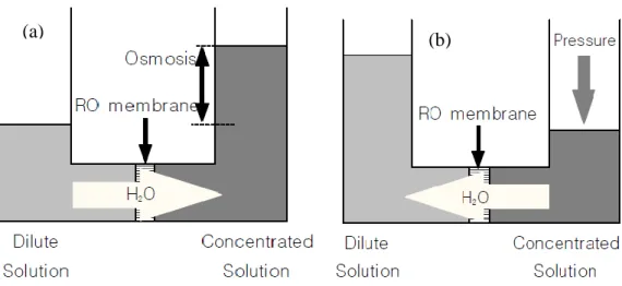
In order to understand the process of Reverse Osmosis, the naturally occurring process of Osmosis must be understood first. Osmosis is a natural phenomenon in which a solvent, usually water, passes through a semipermeable barrier from the side with lower solute concentration to the higher solute concentration side. As shown in Figure 2.3a, water flow continues until chemical potential equilibrium of the solvent is established. At equilibrium, the pressure difference between the two sides of the membrane is equal to the osmotic pressure of the solution. To reverse the flow of water, a pressure difference greater than the osmotic pressure difference is applied as in Figure 2.3b; as a result, separation of water from the solution occurs as pure water flows from the high concentration side to the low concentration side. This phenomenon is termed reverse osmosis.
19 A reverse osmosis membrane acts as the semipermeable barrier to the flow in the RO process, allowing selective passage of a particular species, the solvent, while partially or completely retaining other species, the solutes. Chemical potential gradients across the membrane provide the driving forces for solute and solvent transport across the membrane. The solute chemical potential gradient is usually expressed in terms of concentration; and the solvent chemical potential gradient, is usually expressed in terms of pressure difference across the membrane. Reverse osmosis works by using a high pressure pump to increase the pressure on the feed wastewater side of the RO and force the water across the semi-permeable RO membrane, leaving almost all of dissolved contaminants behind in the reject stream. The amount of pressure required depends on the feed wastewater concentration. The more concentrated the feed, the more pressure is required to overcome the osmotic pressure.
(a) (b)
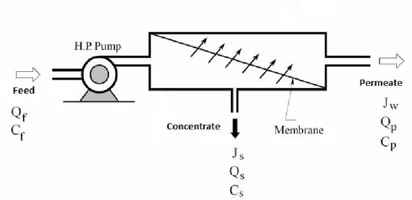
20 2.5.2 RO Process Description
The RO system includes a set of RO membrane elements, housed in pressure vessels that are arranged in a design manner. The RO system is operated in crossflow filtration mode, not in dead end mode, because of the osmotic pressure of rejected solute. Feed wastewater is pumped into a Reverse Osmosis (RO) system and there are two streams coming out of the RO system; permeate which is the water that was pushed through the RO membrane and contains very little contaminants. Another term for permeate is product water. The other stream is the water that contains all of the contaminants that were unable to pass through the RO membrane and is known as the concentrate or reject. The two terms are used interchangeably and mean the same. Figure 2.4 show a reverse osmosis membrane module and its nomenclature. As the feed wastewater enters the RO membrane under pressure that is more than the osmotic pressure, the water molecules pass through the semipermeable membrane and the dissolved contaminants are not allowed to pass and are discharged through the concentrate stream, which goes to drain or can be fed back into the feed supply in some circumstances to be recycled through the RO system. The water that makes it through the RO membrane is called permeate or product water and usually has around 95% of the dissolved contaminants removed from it. In some cases, a pretreatment step is applied before the feed wastewater goes to RO membrane. The primary objective of pretreatment is to make the feed wastewater to the RO compatible with the membrane. Pretreatment is required to increase the efficiency and life expectancy of the membrane elements by minimizing fouling, scaling and degradation of the membrane. However, in this study no pretreatment is applied since the wastewater used is synthetic waste water.
21 In practice, a high-pressure pump driven by electric power or a diesel engine can produce the necessary high pressure. Any solution has a specific osmotic pressure individually depending mainly upon the solute concentration. For the seawater with a salt concentration of 35,000 ppm, the osmotic pressure is about 25 bar and the operating pressure applied on the seawater is usually larger than 55 bar. Reverse osmosis process can separate not only ions and low molecular weight substances in the feed water, but also most impure matters such as bacteria, virus and organic matters like caprolactam by the action of pressure difference across the membrane without any heat treatment and chemical addition.
22
2.6 Mass Transport Mechanism through Membranes
The two accepted models that are used to interpret and describe the process of fluid transport through a membrane are solution-diffusion model and pore-flow model. In solution-diffusion model, the solutes first dissolve in the membrane material and then diffuse through the membrane down due to the concentration gradient. The separation takes place because of the different solubilities of the materials (solvent and solutes) in the membrane which in turn make the solvent and the solutes diffuse through the membrane different rates. The other model is the pore-flow model in which the permeation is caused by a pressure-driven convective flow through the tiny pores in the membrane. The fluid materials are separated because the retentates are hindered at some pores in the membrane while the permeants pass through it. The two models were co-used to interpret the mass transport mechanism through membranes in the nineteenth century, but the pore-flow model was much accepted until the middle of 1940s as the theory behind it is very close to that of the normal conventional filtration. However, the solution-diffusion model was validated in 1940s and was widely used to explain transport of gases through polymeric films.
Diffusion, the basic principle of the solution-diffusion model, is a process in which concentration gradient drives a matter to transport from one part of a system to another. Every single molecule in the membrane medium is randomly and constantly moving (molecular motion). In an isotropic medium, the molecules have no preferred direction of motion. The average displacement of an individual molecule can be calculated at the beginning. However, this is not the issue after sometime and no prediction can be made about the direction in which any individual molecule will move. If a concentration gradient of permeate molecules is formed in the medium, then, simple mass balance calculations show that a net transport of matter will occur from the high concentration to the low concentration region. This hypothesis was proved by Fick theoretically and experimentally in 1855. He then expressed the theory as an equation recognized later as ‘Fick’s law of diffusion’ which states:
23
𝐽𝑖 = -𝐷𝑖𝑑𝑐𝑑𝑥𝑖 (2.1)
where Ji is the rate of transfer of component i or flux (g/cm2 · s) and dci/dx is the
concentration gradient of component i. The term Di is called the diffusion coefficient
(cm2/s) and is a measure of the mobility of the individual molecules. The minus sign shows that the direction of diffusion is down the concentration gradient. Diffusion is an essentially slow process. Using very thin membranes and creating large concentration gradients in the membrane help achieve convenient fluxes across the membrane in diffusion-controlled separation processes.
Pressure-driven convective flow, the basic principle of the pore-flow model, normally defines the flow in a capillary or porous medium. The relative size and the durability of the pores are the only parameters that distinguish the mechanism of the two models. It is difficult to directly measure the average pore diameter in a membrane and must often be deduced from the size of the molecules that permeate the membrane or by some other indirect technique. Keeping these facts in mind, it can be concluded that ultrafiltration and microfiltration membranes are obviously microporous and transport occurs by pore flow while the membrane polymer in reverse osmosis is very dense with no pores and the separation occurs by solution-diffusion.
These membranes show different transport rates for molecules as small as 2 - 5 Å in diameter. The fluxes of permeants through these membranes are also much lower than through the microporous membranes. Transport is best described by the solution-diffusion model. The spaces between the polymer chains in these membranes are less than 5 ˚A in diameter and so are within the normal range of thermal motion of the polymer chains that make up the membrane matrix. Molecules permeate the membrane through free volume elements between the polymer chains that are transient on the timescale of the diffusion processes occurring. There is a third group membranes that contain pores with diameters between 5 Å and 10 Å and are intermediate between truly microporous and truly solution-diffusion membranes. For example, nanofiltration membranes are intermediate between ultrafiltration membranes and reverse osmosis
24 membranes. These membranes have high rejections for the di- and trisaccharides sucrose and raffinose with molecular diameters of 10–13 Å , but freely pass the monosaccharide fructose with a molecular diameter of about 5–6 Å.
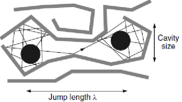
Reverse osmosis uses a large pressure difference across the membrane to separate water from salt solutions and the process involves diffusion of molecules in a dense polymer. The pressure, temperature, and composition of the fluids on either side of the membrane determine the concentration of the diffusing species at the membrane surface in equilibrium with the fluid. Once dissolved in the membrane, individual permeating molecules move by the same random process of molecular diffusion. The advent of powerful computers has allowed the statistical fluctuations in the volumes between polymer chains due to thermal motion to be calculated. Figure 2.4 shows the results of a computer molecular dynamics simulation calculation for a small-volume element of a polymer. The change in position of individual polymer molecules in a small-volume element can be calculated at short enough time intervals to represent the normal thermal motion occurring in a polymeric matrix.
25 2.6.1 Solution-Diffusion Model
Lonsdale et al. (1965) developed the solution-diffusion model assuming that the solute and the solvent dissolve in the homogeneous non porous surface layer of the membrane and then are transported by a diffusion mechanism under the chemical potential gradient in an uncoupled manner. The solvent or water flux Jw is defined as the
volume of water passing through a unit area of the membrane. The water flux, Jw
according to solute diffusion transport mechanism is given by:
𝐽𝑤 = 𝐾𝑤 (∆𝑃 − ∆𝜋) (2.2)
where ΔP is the pressure difference across the membrane, Δπ is the osmotic pressure differential across the membrane, and 𝐾𝑤 is a constant. As this equation shows, at low
applied pressure, when ΔP < Δπ, water flows from the dilute to the concentrated salt-solution side of the membrane by normal osmosis. When ΔP = Δπ, no flow occurs, and when the applied pressure is higher than the osmotic pressure, ΔP > Δπ, water flows from the concentrated to the dilute salt-solution side of the membrane.
The salt flux 𝐽𝑠 across a reverse osmosis membrane is described by the equation:
𝐽𝑠 = 𝐾𝑠(𝐶𝑠𝐹− 𝐶𝑠𝑃), ∆𝐶𝑃 ≅ 0, 𝐽𝑠 = 𝐾𝑠(∆𝐶𝐹) (2.3)
where 𝐾𝑠 is the salt permeability constant and 𝐶𝑠𝐹 and 𝐶𝑠𝑃, respectively, are the solute
concentrations on the feed and permeate sides of the membrane. The concentration of solute in the permeate solution (𝐶𝑠𝑃) is usually much smaller than the concentration in
the feed (𝐶𝑠𝐹), so equation (2.3) can be simplified to:
26 Equations (2.2) and (2.4) show that for a given membrane:
a) The rate of water flow through a membrane is proportional to net driving pressure difference across the membrane.
b) The rate of solute flow through a membrane is proportional to the concentration differential across the membrane and is independent of applied pressure. This means that the membrane becomes more selective as the pressure increases.
2.6.2 Concentration Polarization (CP)
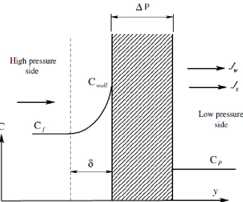
As water flows through the membrane and salts are rejected by the membrane, a boundary layer is formed near the membrane surface in which the salt concentration exceeds the salt concentration in the bulk solution as shown Figure 2.6. This increase of salt concentration is called concentration polarization (CP) (Matthiasson and Sivik, 1980; Potts et al., 1981). During the initial transient state, the solute molecules are transported to the membrane surface via advection as accumulation of solute takes place, the advective transport is balanced by back diffusion, and at steady state a concentration profile exists. Concentration polarization as mentioned before leads to serious problems during membrane operation as reduces the permeating component’s concentration difference across the membrane, thereby lowering its flux and the membrane selectivity.
27 The concentration polarization factor (CPF) can be defined as the ratio of solute concentration at the membrane surface (Cwall ) to bulk concentration (Cb ).
CPF = Cwall/ Cb (2.5)
An increase in permeate flux will increase the delivery rate of ions to the membrane surface and increasing value of Cwall. On the other hand, increasing the feed
flow increases the turbulence and reduces the thickness of the high concentration layer near the membrane surface.
28 2.6.3 Model Equations
There are some parameters that are used to judge the performance of an RO system and also used for design considerations. An RO system has instrumentation that displays quality, flow, pressure and sometimes other data like temperature or hours of operation. In order to accurately measure the performance of an RO system, the following operation parameters must be known at a minimum: (1) feed pressure, (2) permeate pressure, (3) concentrate pressure, (4) feed conductivity, (5) permeate conductivity, (6) feed flow, (7) permeate flow and (8) temperature. Below are some other parameters that are normally calculated to measure the performance of the RO system.
Rejection Percentage (%)
Salt rejection is a measure of how well a membrane element rejects the passage of dissolved ions. Although an RO element may be called upon to reject many different ions, sodium chloride (NaCl) is used as a measurement standard. With few exceptions RO membranes reject divalent ions better than monovalent ions such as sodium and chloride. Therefore, if a membrane exhibits excellent rejection of NaCl, the membrane can be expected to perform even better in rejecting the passage of such divalent ions as iron, calcium, magnesium, and sulfate. Thus NaCl (salt) rejection has been universally accepted as the standard for measuring a membrane element’s ionic rejection performance. The rejection percentage can be calculated using the following equation:
Rejection (%) = 𝐶𝑜𝑛𝑐𝐶𝑜𝑛𝑐𝑓 − 𝐶𝑜𝑛𝑐𝑝
𝑓 × 100% (2.6)
Keeping salt rejection in perspective, it is also important to bear in mind that evaluation of long-term RO element performance involves consideration of more than salt rejection. Membrane flux, element flow capacity, system pressure requirements, membrane fouling rates, membrane response to cleaning operations and tolerance of cleaning procedures, and the durability of the element all can be important factors in
29 choosing an element. The higher the salt rejection, the better the system is performing. A low salt rejection can mean that the membranes require cleaning or replacement.
Passage Percentage (%)
This is simply the inverse of rejection percentage described in the previous section. This is the amount of salts that are passing through the RO system expressed as a percentage. The lower the salt passage, the better the system is performing. A high salt passage can mean that the membranes require cleaning or replacement.
Passage (%) = 1- Rejection (%) (2.7)
Recovery Percentage (%)
Percent Recovery is the amount of water that is being ‘recovered’ as good permeate water. The higher the recovery percentage means that less water to be drained as concentrate and more water to be saved as permeate. However, if the recovery percent is too high for the RO design then it can lead to larger problems due to scaling and fouling. The recovery percent for an RO system is established with the help of design software taking into consideration numerous factors such as feed water chemistry and RO pretreatment before the RO system. Therefore, the proper recovery percent at which an RO should operate at depends on the objective that a certain RO system is designed for. By calculating the recovery percent, it can be determined if the system is operating outside of the intended design. The calculation for recovery percent is below:
30
Concentration Factor
The concentration factor is related to the RO system recovery and is an important equation for RO system design. The more water recovered as permeate (the higher the % recovery), the more concentrated salts and contaminants collected in the concentrate stream. This can lead to higher potential for scaling on the surface of the RO membrane when the concentration factor is too high for the system design and feed water composition.
Concentration Factor = 1
1−𝑅𝑒𝑐𝑜𝑣𝑒𝑟𝑦 𝑅𝑎𝑡𝑒 (2.9)
Flux
The main design parameters for a reverse osmosis unit are the production per unit area of membrane and water quality. Water transport through the membrane is expressed as a permeate flux. The flux is generally defined as the volumetric flow rate of water through a given membrane area. In the case of RO, the unit of flux is expressed as liters of water per square meter of membrane area per hour (lmh) or gallons per square foot per day (gfd). The permeate flux is proportional to the net driving pressure (NDP). The water flux, 𝐽𝑖, is linked to the pressure and concentration gradients across the membrane by the equation:
𝐽𝑖 = 𝐴(∆𝑃 − ∆𝜋) (2.10)
where ΔP is the pressure difference across the membrane, Δπ is the osmotic pressure differential across the membrane, and A is a constant. As this equation shows, at low applied pressure, when ΔP < Δπ, water flows from the dilute to the concentrated salt-solution side of the membrane by normal osmosis. When ΔP = Δπ, no flow occurs, and when the applied pressure is higher than the osmotic pressure, ΔP > Δπ, water flows from the concentrated to the dilute salt-solution side of the membrane.
31
2.7 Polymers Used as Membrane Materials
Synthetic organic polymers are raw material for the production of most MF, UF, RO, and NF membranes. The production of MF and UF membranes under different membrane formation conditions cause them to have different pore sizes. However, they are made from the same material (Pinnau et al, 2000). The typically used polymers in MF and UF production include, but not limited to, poly(vinylidene fluoride), polysulfone, poly(acrylonitrile) and poly(acrylonitrile)-poly(vinyl chloride) copolymers. Another often used polymer for UF membranes is Poly(ether sulfone) while cellulose acetate-cellulose nitrate blends, nylons, and poly(tetrafluoroethylene) are used for MF membranes (Baker, 2004). RO membranes are characteristically made from either cellulose acetate or polysulfone coated with aromatic polyamides. Like the RO membranes, NF membranes are made from cellulose acetate blends or polyamide composites. Sometimes, the UF membranes such as sulfonated polysulfone are modified to obtain RO or NF membranes (Nunes et al, 2001).
Inorganic materials such as ceramics or metals are used to prepare membranes (Baker, 2004). Ceramic membranes are normally microporous and exhibit very good characteristics like thermally stable, chemically resistant. They are ften used for microfiltration. However, they have some drawbacks like high cost and mechanical fragility which have limited their industrial use. Stainless steel is the core material used to make metallic membranes which are normally very finely porous and are mostly used in gas separations, and sometimes in water filtration at higher temperature or as a membrane support.
32 2.7.1 Cellulose-Based Membranes
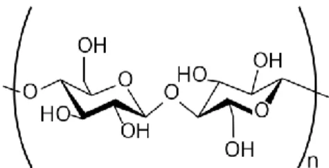
Cellulose-Based membranes are made from acetylated cellulose (CA). Cellulose is a naturally occurring polymer found in plants such as cotton. It is a linear, rod-like material that is relatively inflexible, which renders CA membranes mechanically robust. The degree of acetylation describes how many of the pendant OH groups on the cellulose (see Figure 6) are replaced with acetyl groups, CH3COO. The degree of
acetylation can range from 0 to 3 where 0 represents unreacted cellulose and 3 corresponds to completely substituted cellulose, also called cellulose triacetate (CTA). The degree of acetylation has a large effect on the resulting membrane properties. A high degree of acetylation gives high salt selection but low permeability (Kesting, 1977). Lower degrees of acetylation yield membranes with lower rejection but higher flux.
Figure 2.7 Chemical structure of a cellulose repeat unit
Commercial CA membranes used for reverse osmosis have a degree of acetylation of about 2.7. This composition provides a good balance between salt rejection and permeate flux. Some membranes also use blends of CA and CTA. Blending CA with CTA increases the mechanical stability and resistance to hydrolysis but decreases the permeability. CA membranes offer several advantages over other RO membranes on the market. They are relatively easy to make and they have excellent mechanical properties. They are also relatively resistant to attack by chlorine. CA membranes can tolerate up to 5 ppm of free chlorine, which is much higher than the tolerance shown by other membranes such as those based on aromatic polyamides. CA membranes also possess shortcomings which new membranes have tried to address. CA membranes tend to hydrolyze over time, which decreases their selectivity. Also, they are
33 extremely sensitive to changes in pH and are stable only in pH ranges of 4 to 6. Salt rejection of CA membranes decreases as temperature increases. Therefore, feed water temperature typically does not exceed 35°C (Baker, 2004).
2.7.2 Thin Film Composite Membranes
Cellulose acetate membranes were the dominant choice for RO membranes until the advent of thin film composite (TFC) RO membranes in 1972. Based on aromatic polyamides, TFC membrane fluxes and rejections surpassed those of CA. Most TFC membranes are made with a porous, highly permeable support such as polysulfone, which is coated with a cross-linked aromatic polyamide thin film. The coating provides the salt rejection properties of the membrane. The first TFC RO membrane was developed by John Cadotte at North Star Research. He used interfacial polymerization to create a polyamide coating on a support. This polyamide coating was based on the reaction between m-phenyl diamine and trimesoyl chloride (Cadotte, 1985). Variations of this chemistry are still used today to produce cross-linked membranes for commercial RO membranes.
In addition to high rejection and high flux, TFC membranes offer other advantages over CA membranes. For one, they can also reject some low molecular weight organics. They are also stable over a larger pH range and at higher temperatures than CA. However, one drawback of TFC membranes is their sensitivity to chlorine. TFC membranes are highly susceptible to attack by chlorine. The polyamide is believed to undergo ring chlorination, which disrupts hydrogen bonding between the chains and degrades the polymer matrix (Alvonitis et al, 1992). This phenomenon results in a drastic reduction in salt rejection. Unfortunately, most TFC membranes can only tolerate up to 1000 ppm-hrs of chlorine exposure. This limit is far less than the CA tolerance and means that additional pre-treatment steps to remove chlorine must be taken before feed water is exposed to polyamide TFC membranes.
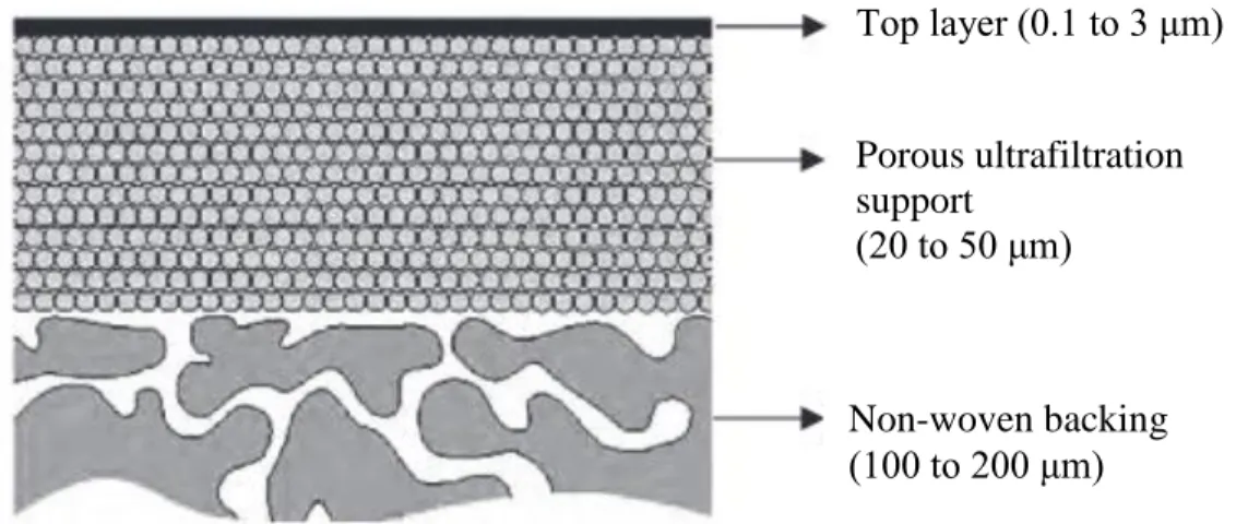
34 A TFC membrane generally consists of three layers (Fig. 2.8). The ultra-thin top layer is the actual selective barrier in the composite, and is responsible for the molecular selectivity. This top layer is supported by a porous sublayer; usually an asymmetric ultrafiltration or microfiltration membrane that provides a sufficiently smooth surface to accommodate a defect free thin top layer. The third layer is a non-woven reinforcing fabric that provides for the main part of the mechanical strength of the composite structure.
One more advantage of TFC membranes is that the specific features of each individual layer can be tailored independently to obtain a composite with desirable properties. In contrast, in asymmetric membranes consisting of a single material, compromises must be made with respect to contradicting demands on materials properties of the dense top layer and the porous sub structure. The top layer of a TFC can be chosen independently from a vast variety of chemical structures, including cross-linked polymeric compositions that can be formed into thin films. The hydrophilicity, and thus the flux, and chemical resistance can be tuned independent of the TFC sublayers. The ultra-porous sub layer is generally prepared on top of the non-woven fabric via the phase inversion technique. This sub layer can also be tailored independently, aiming at minimum resistance to permeate flow combined with enhanced compression resistance. Top layer (0.1 to 3 μm) Porous ultrafiltration support (20 to 50 μm) Non-woven backing (100 to 200 μm)